chillyche Posted June 24, 2012 Share Posted June 24, 2012 I have nothing to add that hasn't already been said, but I feel like I have to applaud, loudly, along with everybody else. I suppose, what CAN be said is that as you spend time refining the design, making everything work as much as possible, combining canon design with real world physical space considerations, you're not only creating the definitive CGI VF-1, but you're also creating a new sort of reference for all the other artists that hope to create their own VF-1s. I don't have the modeling skill you possess, and I doubt that I will ever put in the time necessary to get there, as modeling is a fun hobby for me, and was never a professional consideration. But I do like to model, and I do like to make stuff, and I do get frustrated with how certain things I'd like to model seem fairly impossible to put together -- too many or too few references, 2D references that cannot exist in 3D, etc, you know the issues. Your model -- as well as your process -- will help all of us hobbyists to create satisfying models on our own. And that deserves another big thank you, along with the "thank you for making something that is really awesome, and brings me great joy when I look at how awesome it is!" But I also am going to scowl at you, because inside me there is a jealous kid that is mad that your work is so great. But, then I'm going to shrug that off, because I'm a freakin' grown-up. And once again congratulate you on making the dopest VF-1 I have ever seen, and probably this board has ever seen. Also, does JewLew know that you're totally shattering his record of dopest VF-1? Quote Link to comment Share on other sites More sharing options...
danbickell Posted June 24, 2012 Author Share Posted June 24, 2012 Thanks! And Thanks to all of you folks for all the support. Art doesn't have much of a point unless it is shared, and I really appreciate having such a great group of Macross fans and experts who share this common passion. I've become very accustomed to the process of other artists seeing my works progress in a professional environment, and the constant critique that comes along with that. There's no better group in the world to share this particular project with. I haven't shown Jason any of this stuff yet, though I do recall that he was pushing me to take a stab at a "high poly" valk when we last worked together more than a decade ago. His model was just starting out back then. I'll show him when it is all done. I've been making plenty of progress with the chest block over the last week, but it certainly is proving to be frustrating. When you look at all the toys and transformable models, and every other CG model I have seen, there is a much higher degree of compromise to the original designs here than any other part of the VF-1. This has always frustrated me, and is a big part of what I hope to improve upon. The thing is, the designs are just plain faulty here, and require a lot of that "anime magic" to work like they are supposed to. There are a few things I've managed to work out so far that I haven't seen done before, but I'm finding there are still major parts that need to be done just like all the other interpretations (and not like the lineart has always shown). I'm mentally trying to get over some of these compromises, after doing my due diligence to find solutions. One solution I am pleased with is this: Those shoulder lights can never be quite as big as they are often drawn, simply because they would not fit under the chest in fighter mode. They can't recess into the back because the wings hinge directly beneath them. They are considerably reduced in size on every transformable toy and model for this reason. Also, all the toys and models just leave an open slot in the top of the chest to accomodate them. Some CG models have added a sliding panel that would open up to accomodate them, but I dislike this solution. Fortunately, I managed to keep the lights decently big on my model (and still leave enough clearance to detail them just like this drawing), and worked it out so that panel (outlined in green) can hinge out of the way for it in fighter. The biggest problem area is the shoulder hinge itself: This hinge defines the proportions of the battroid torso, and it isn't as simple as all the designs make it seem. I really wish it could look exactly like this drawing, but it just isn't possible for a number of reasons. If it were that wide (extending all the way to the shoulder), the front corner would have to stick out of the chest in fighter since the chest is angled. It also isn't leaving any space for the fairings on the underside of the chest and back either. Those fairings seem to just disappear in all the original lineart designs, and they are considerably reduced in size on all the toys and transformable models (or even just left out altogether in some cases). The Hasegawa 1/48 model has the largest underside fairings I've ever seen, and it looks really great in fighter, but they just can't actually be that big (it would push the chest and back too far apart in battroid). I've decided to model them as large as they are typically shown in the fighter lineart, but not reduced as much as they generally are in the toys. I'm folding in a portion of the fairings on the back piece to accomodate the arms. That TanJ guy did this as well on his model, but there are actually panel lines in the original designs that work well for this that he didn't choose to follow. I explored a number of schemes to fold away the chest portions of the fairings as well, but nothing really worked. The main problem is that the LERX needs to fit inside these on the chest in batttroid. The toys got around this by reducing the fairings dramatically in size, so that the LERX portion of the fairings ends up outside of the reduced chest fairings. Thankfully, I was able to size the fairings where they are right about the "correct" size, and the LERX will still fit inside of them in battroid. Ultimately, the portions of those underside fairings at the shoulders have to be visible, and the shoulder hinge panel needs to be narrowed to accomodate them (like all the other toys and models). On top of that, the panel needs to be much longer (front to back in battroid) than these designs always show. They are especially long on the transformable toys, which makes the battroid chests too long (front to back). I came up with a slighly more complicated hinge system that minimizes how much this panel needs to be lengthend. It is still longer than shown in this drawing, but short enough to pull together the chest and back to the minimum distance (so that the wings will be just behind the bottom of the nose in battroid). The problem here is that hinge size is no longer long enough to gap the distance required for fighter. The solution is that the internal portion of the LERX (that the hinge attaches to) needs a sliding extension piece that extends the hinge to fit in fighter. Fortunately, that works quite well. I also ended up starting over from scratch on the LERX, and made them much beefier than I had them before. This actually made them look much closer to how they appear in one of my favorite of the DYRL drawings (the one currently in my avatar), and it also helps with the proportions of the Hasegawa 1/48 (where the legs are lowered in fighter to give them the nice size for battroid while keeping them nice and straight vs. their angled interpretation on the old 1/72 models) as it takes up the space they added between the LERX and the intakes. Most importantly, it allows much needed room for the leg transformation mechanism, which I am now much more confident about. There seems to be plenty of space there now, and I should be able to avoid ending up with parts that look rediculously too thin there. I'm still experimenting with space for the battroid side covers. That's going to be a real trick to pull off well (which is why most interpretations just ignore them completely). Hopefully I can make that work decently. Any reference you guys might have would be greatly appreciated. I see practically nothing of it in any of the original lineart that I have. Quote Link to comment Share on other sites More sharing options...
EXO Posted June 24, 2012 Share Posted June 24, 2012 I don't know if you can understand this crude doodle or if it would even work, but maybe it can fold up like this? Quote Link to comment Share on other sites More sharing options...
danbickell Posted June 25, 2012 Author Share Posted June 25, 2012 I don't know if you can understand this crude doodle or if it would even work, but maybe it can fold up like this? That is very much like what I have going with that small chest panel for clearing the shoulder lights. The problem with doing panels like that attached to the back piece is that they would have to blow through the hinges that connect the back to the LERX. Also, since the chest and back pieces have to be much farther apart in battroid than that small panel in the drawing shows, an appropriately sized panel would be too big to fit there in fighter (would stick too far down in fighter, where the arms need to go). Quote Link to comment Share on other sites More sharing options...
EXO Posted June 28, 2012 Share Posted June 28, 2012 Been trying different stuff... any luck? Quote Link to comment Share on other sites More sharing options...
danbickell Posted June 28, 2012 Author Share Posted June 28, 2012 Been trying different stuff... any luck? I've settled for now on how the battroid shoulders will look. I'm just happy it will be gapless and clean, the shoulder lights are as big as they can be and still fit, and the back to chest distance is as minimal as it can be. Even if that hinge panel could extend all the way out to the shoulders, it would still have to be quite a bit longer front to back than shown anyway. Working out the LERX leg transformation mechanism now, and still pondering the battroid side covers. The only references I currently have for the side covers are the Yamato 1/48 and 1/60 parts that came with the GBP sets, and the Hasegawa 1/72 battroid kits. Anything else anybody might to share would be appreciated. Quote Link to comment Share on other sites More sharing options...
EXO Posted June 28, 2012 Share Posted June 28, 2012 This is what I based my resin kits on... http://www.macrosswo...howtopic=33778 I also have the TRex kit, which is what they based the new 1/60 side covers on. http://www.macrosswo...ndpost&p=925720 http://www.macrosswo...012/05/main.jpg Those side covers aren't accurate though, because you still need the flaps at the end they just look like the ones I made. Though I do like the detail on the ones that came with the GBP more. Quote Link to comment Share on other sites More sharing options...
danbickell Posted June 30, 2012 Author Share Posted June 30, 2012 Thanks, those links are useful. I remember that TRex kit now. Never had it, but they certainly had some interesting ideas. There's a decent sized version of this one in the Kawamori Design Works book too: The side covers for the Hasegawa 1/72 battroid kits are quite similar, but they have toothed joint down the middle, which makes a lot of sense. However it will work, it will certainly have to fold like that down the middle. A buddy of mind had send me a phone camera pic of the thruster version from the Max and Millia fight in the TV series, so I was glad to see those screen caps in the Yamato kit thread. I wouldn't even begin to try to make that work, though. Not only could that version not fold up down the middle (or anywhere else), but it would require more space (that doesn't exist) for the thrusters as well. Tinkering with the model now, trying to see what I can come up with. I'm itching to get all this blocked out so I can get to the detailing! Quote Link to comment Share on other sites More sharing options...
Steve71 Posted June 30, 2012 Share Posted June 30, 2012 Not sure what I can add that hasn't been said before, but looking at your images makes me respond. That is incredible. Thanks for sharing - It is so cool see a labor of love. Very inspirational. Quote Link to comment Share on other sites More sharing options...
danbickell Posted July 3, 2012 Author Share Posted July 3, 2012 Wow, this thread recently passed 10k views! Thanks for all the interest! Been making great progress lately. The torso block is nearly finalized shape-wise, and many of my concerns have worked out satisfactorily. I decided to do the intakes before getting into the LERX leg transformation mechanism, and those have proved to be one of the trickiest shapes to get right yet (especially with working intake covers), but I'm quite pleased with how they've turned out so far. Should be moving on to the fun detail work soon. I got a bit side-tracked today. A member PMed me, inquiring about cross-sectional plans for building a physical model. This happens to be something I've been thinking about doing all along, so after a bit of discussion (while I was at the office today), I decided to experiment with just the completed nose section when I got home. Several hours later... Full-sized versions available here: http://i362.photobucket.com/albums/oo68/danbickell/vf1_nose_plan.jpg http://i362.photobucket.com/albums/oo68/danbickell/vf1_nose_plan_overlay.jpg In theory, you should be able to print the full-sized version of the big plans at the correct dpi for the desired scale. Doing some quick math: 29 pixels = 100 mm = 3.937 inches 1/1 scale = 7.366 dpi 1/12 scale = 88.39 dpi 1/24 scale = 176.78 dpi 1/48 scale = 353.57 dpi Checking the math, at 1/48 scale the plans say the nose section should be 4.75 ", which accurately matches the Hasegawa 1/48. Confirmed. That was fun! I think I will keep doing these as I get more of the model complete. Quote Link to comment Share on other sites More sharing options...
Ganbare Posted July 4, 2012 Share Posted July 4, 2012 Impressive work. Keep it up. Quote Link to comment Share on other sites More sharing options...
TehPW Posted July 4, 2012 Share Posted July 4, 2012 wow... with those CAD looking diagrams, you could actually build a mock-up of the cockpit fuselage (for example, for filming a live action film) :wub: Quote Link to comment Share on other sites More sharing options...
PetarB Posted July 4, 2012 Share Posted July 4, 2012 Hey Dan, just checking into this thread after a long absence, and your work is still fantastic. Thanks for all the renders and hard work modelling! Quote Link to comment Share on other sites More sharing options...
danbickell Posted July 5, 2012 Author Share Posted July 5, 2012 Here's an additional top image for the nose plans, as requested. The scale matches the side plan with the cross sections exactly. Link to the full-size version: http://i362.photobucket.com/albums/oo68/danbickell/vf1_nose_plan_top.jpg Getting plenty of good work in today. I decided to just finish the intakes while I'm at it. I just finished with the intake covers, which work nicely fully open and closed, and with several options in between (for supersonic configurations). I should at least be able to post some renders of the completed intakes by the end of the day. I have lots of test renders of the torso-block with the completed nose and head, in both fighter and battroid, but I'm hesitant to post them until they're all detailed and finished. I hate looking back early in this thread at the early shots before the nose was all paneled and detailed, and I wince every time they pop up while I'm doing an image search on the web for reference material. I might post a few anyway, though. It's just cool to see so much more of it coming together finally, even without the details there yet. Quote Link to comment Share on other sites More sharing options...
GMK Posted July 5, 2012 Share Posted July 5, 2012 C'mon Dan, Post the chest models! Thanks for the cross-sections & keep up the great work. Greg Quote Link to comment Share on other sites More sharing options...
Hikaru2 Posted July 5, 2012 Share Posted July 5, 2012 Good stuff dude. Cant wait to see the finished intakes (thinking of each waypont makes the trip to the end seem shorter, right????) Quote Link to comment Share on other sites More sharing options...
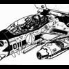
nightmareB4macross Posted July 7, 2012 Share Posted July 7, 2012 Hi Dan, Hope I'm not intruding, but after reviewing the what you have contemplated and what is shown on the lineart, I offer you this solution. Collapsible lights. Clavicle covers that swing down towards the rear, to allow clearances for components under the chest and intake ducts. Quote Link to comment Share on other sites More sharing options...
danbickell Posted July 7, 2012 Author Share Posted July 7, 2012 Hi Dan, Hope I'm not intruding, but after reviewing the what you have contemplated and what is shown on the lineart, I offer you this solution. Collapsible lights. Clavicle covers that swing down towards the rear, to allow clearances for components under the chest and intake ducts. Interesting Ideas! I always appreciate input. The collapsible lights could certainly help make the lights beefier front to back. I might try that out. This particular drawing has the light itself popped out proud of the surface, so what I might just do is have that part retract inside. That way I can still make the part thicker front-back, without adding any lip around the outside. I thought about doing something like that with the clavicle cover (good name!), but ended up deciding against it for a couple of reasons: 1) it would have to hinge off the shoulder hinge to do that, causing interference with where the shoulder hinge connects to the LERX underneath the chest, and 2) that vernier thruster on the clavicle cover requires clearance underneath it. That's why I ended up hinging the panel where I did, connected to the chest, swing towards the nose. There's plenty of room for the vernier thruster that way, it clears plenty of space for the lights, and even ended up allowing clearance for a taller shoulder hinge to which I added an extension that covers closer to the arms. I've been working on this every day this week, but I'm still not quite done with those intakes. I've gone back and re-worked a bunch, but I'm about 97% done with them at the moment. I should post some renders of them later tonight, for sure this time! Quote Link to comment Share on other sites More sharing options...
danbickell Posted July 7, 2012 Author Share Posted July 7, 2012 As promised (for once!), I think I'm finally done with the intakes. Have a look: The design I decided on for the hip joint is loosely based on an old 1/72 battroid vinyl kit (don't remember who made it). This type of design solves a few problems that often bothers me about the VF-1 design. It provides room for a good sized ball joint while not intruding into the space for the inside of the intake, and it takes up a good chunk of the space between the intake and the nose blisters in battroid. I really don't like long skinny hip pins, and this allows for a beefy pin that is nice and short, and not super visible in battroid. On top of the intake is the connection point for the transformation mechanism under the LERX. Also included are the 3 vents on the outer sides. These are prominent on the Hasegawa 1/48 model, and vaguely shown in at least one of the original fighter lineart drawings, and more prominently in the more detailed battroid lineart. Only a small portion of them protrudes below the fairings on the underside of the LERX and chest, but they are more visible in battroid. I went through a few iterations of the forward-facing vernier thrusters (the brakes!). That's the same thruster bell from the nose verniers, for consistency. I decided to make the vents on the rear of these more decidedly rear facings, as would make sense aerodynamically. Most of the time these are interpreted as if they would just vent straight out to the sides. Also, instead of making all 3 the same height (like most models, even the Hasegawa 1/48), I decides to have them follow the curve of the part. One of the trickier parts of this, even though it might not look like it, is the intake covers. These were often drawn, and have often been interpreted, in ways that just don't make sense. They would have to pivot on multiple axes and change shape much of the time. The Hasegawa 1/48 did better than most by having the hinges all parallel, and the front one not following the angle of the outer intake. They also cheated the inside of the intake as very squared off, which I don't like the look of. The trick was getting nice curved corners on the intake, with a nice flowing aerodynamic intake interior, and intake covers that fit well in any position between fully open and closed. After lots of tweaking, I finally got it to a point where I was happy with it, and you can get quite a number of configurations suitable for different conditions. Of course, I had to have the fan nice and visible! It actually sits a little behind the intake (inside that black temp cover I added for these renders), and will be contained inside the joint between the intake and the thighs. It is a 32 blade design, complete with recessed bolts for each blade in the cone. I have fun making sound effects while I spin it. I'm still not quite ready to show it all together with the yet-to-be-detailed parts, but here's some shots with both intakes in context with the completed nose and head. Quote Link to comment Share on other sites More sharing options...
danbickell Posted July 7, 2012 Author Share Posted July 7, 2012 Ok, here are a couple of teaser images, with the rest of the WIP undetailed parts I have worked out so far: One of the parts I'm focusing on here is the connection between the nose and the chest. In a number of the DYRL drawings, this is shown as not flush between the 2, like on the TV version. The side nose profile cutaway sketch shows this, as do a number of the detail drawings done for the DYRL cockpit. I've always liked this, but never seen it done quite like it was drawn. The Club-M 1/48 had the details from one of the detail sketches as panel lines, but made the connection flush. Here's a shot of it all in battroid mode: I'm pretty happy with where the proportions are now, and that the top of the shoulders is without gaps. I should be able to detail that to look pretty close to that DYRL battroid sketch we keep referencing. The only open space up there is that area behind the head, which will get filled up a bit by all the cool details on the underside of that hinged back panel. Of course, this is all what I call "block-out" geometry. It will get considerably refined as it gets closer to final and detailed. I can't wait... Quote Link to comment Share on other sites More sharing options...
mechaninac Posted July 7, 2012 Share Posted July 7, 2012 Un-freak'n-real! Thanks for just making me poop my pants; expect a laundering bill from me shortly. I don't believe I've witnessed such meticulous attention to detail in any fan-made 3D mesh WIP, ever. I'm truly in awe! Quick question, are your meshes "water-tight"? if so, you could have them built in any number of additive manufacturing processes and have yourself the definitive, fully transformable, VF-1... in any scale your wallet and ambition desires. Quote Link to comment Share on other sites More sharing options...
danbickell Posted July 7, 2012 Author Share Posted July 7, 2012 For the most part, the meshes are water-tight. I'd say about 90%. There are small details in some places that would need to be booleaned together, and I would have to add some back faces to close some parts off, but I've always had 3d printing in the back of my mind for this. I might try a piece or 2 as a test in the near future. Quote Link to comment Share on other sites More sharing options...
EXO Posted July 8, 2012 Share Posted July 8, 2012 Apparently my pants aren't water tight! Wheeeee!!! OMG! I so want to do an SD version of this, but I doubt I can make it transform without all the parts smashing into each other. Quote Link to comment Share on other sites More sharing options...
GMK Posted July 8, 2012 Share Posted July 8, 2012 Dan, I may've missed it, but does your nose model include the retractable boarding ladder? Keep up the great work. Greg Quote Link to comment Share on other sites More sharing options...
danbickell Posted July 8, 2012 Author Share Posted July 8, 2012 Apparently my pants aren't water tight! Wheeeee!!! OMG! I so want to do an SD version of this, but I doubt I can make it transform without all the parts smashing into each other. If anything, I think making an SD version could help out the transformation more than hurt it. Proportionally, you can give yourself bigger volumes to work with inside an SD shape. You could probably probably even make things like the battroid seat egress work, with a big fat nose section. The beauty of it is that you can proportion anything to where you would need it to be. That sounds WAY easier than making everything work while constrained to the original shapes and volumes. The trick would be coming up with proprotions that would look good and work at the same time. I could see the head being a problem, as big as you might want to make it SD. Dan, I may've missed it, but does your nose model include the retractable boarding ladder? Keep up the great work. Greg I have not actually made the working ladder yet, but I did plan for it. The panel lines for it are there, and it would just need the telescoping mechanism added. I should add it when I go back to the nose to add the hip pin mechanism. Thanks for reminding me! I decided on the telescoping ladder design from this example of the original lineart (which also shows those vents on the outer upper corners of the intakes BTW): The grip hole is also in my favorite of the DYRL detail drawings. This setup works nicely for me, and also matches the Hasegawa 1/48 plans. Despite the "NO STEP" on the LERX, I can't imagine a pilot wouldn't use the LERX as well, as it is lined up perfectly with the ladder and grip point. Quote Link to comment Share on other sites More sharing options...
Mommar Posted July 9, 2012 Share Posted July 9, 2012 Wow. Just based on that test render of the torso section that's going to be one brutish looking Battroid. I'm curious how the shoulders/arms are going to look since you've been so unhappy with the twig arms we see on other models and the Master File books. Quote Link to comment Share on other sites More sharing options...
danbickell Posted July 9, 2012 Author Share Posted July 9, 2012 Wow. Just based on that test render of the torso section that's going to be one brutish looking Battroid. I'm curious how the shoulders/arms are going to look since you've been so unhappy with the twig arms we see on other models and the Master File books. Well, where they went wrong with the Master File books was having skinny legs. It looks quite close to the Hasegawa 1/72 model, but with the legs straightened out (but the same proportion). This doesn't leave much space for arms, unless they were to protrude quite a bit in fighter. So, the end result is the twig arms. All the original lineart takes liberties with the proportions all over the place. They shrink the legs and arms down to make a sleeker looking fighter, and then they get big and beefy in battroid mode. Likewise, they beef up the chest and shrink the nose in all the battroid lineart, where they keep the nose long and the chest flatter in the fighter lineart. More anime magic. That goes right back to why I've been so enamored with the Hasegawa 1/48 proportions. They bulked up the legs to similar proportions to the Yamato 1/60 V2, and lowered them to keep them straight. The whole profile is a bit taller than the original fighter designs with a taller chest and lower legs, but I think it looks really good (gives it a bit of an Su-27 flavor), and it really helps out the proportions for battroid. There is plenty of space left for nice big arms, without having them protrude too low (like the Yamato 1/48 arms). I found it to be such a beautiful, realistic, and a bit more modern interpretation of the iconic design, that it drove my motivation to start this model in the first place. See page 2 of this thread for the old image I posted demonstrating the proportional differences between the various models. Quote Link to comment Share on other sites More sharing options...
Mommar Posted July 9, 2012 Share Posted July 9, 2012 I remember those comparison pictures. But they're just 2D sketches. For me at least, since I don't have any of those Hase models, it was hard to really picture how the proportions would change anything. Especially considering it's not just the face the legs are so skinny lengthwise. I'm wondering about the width of the arms as well when they fit between the legs. Seeing this thing in 3D from different angles makes a big difference in understanding what you were getting at. Looking back at that pic from the Master File I really, really hate the design they decided to go with now. Quote Link to comment Share on other sites More sharing options...
Knight26 Posted July 9, 2012 Share Posted July 9, 2012 I am liking what I see so far, 1 suggest though involving the hip intake fan. Is there a way you can either have it collapse it's blades, or at least turn them so that airflow going in is fairly uninterupted when in forward flight? Those intake fans are primarily for gerwalk and battroid mode to assist with airflow, though realistically they are not needed if the main engines are as insanely powerful as has been stated in all official sources. Quote Link to comment Share on other sites More sharing options...
Mr March Posted July 9, 2012 Share Posted July 9, 2012 I always loved the proportions of the Hasegawa Battroids, but I don't know if they would translate/transform well into a nicely proportioned fighter. It would be really cool if they did, because I've long felt the Hasegawa battroid was the definitive non-animated version of the VF-1 Valkyrie robot mode. Quote Link to comment Share on other sites More sharing options...
VF5SS Posted July 9, 2012 Share Posted July 9, 2012 I thought the Battroid illustrations from the second VF-1 Master File were pretty well done. Although with the way they mix CGI, model kits, and other artwork it always seems like no one was on the same page as far as what the VF-1 should look like. Quote Link to comment Share on other sites More sharing options...
danbickell Posted July 9, 2012 Author Share Posted July 9, 2012 I am liking what I see so far, 1 suggest though involving the hip intake fan. Is there a way you can either have it collapse it's blades, or at least turn them so that airflow going in is fairly uninterupted when in forward flight? Those intake fans are primarily for gerwalk and battroid mode to assist with airflow, though realistically they are not needed if the main engines are as insanely powerful as has been stated in all official sources. There's no reason the fan blades couldn't be made to turn their angles. I did a fair amount of research, looking at modern turbojet fans, and I don't recall seeing any with variable pitch blades. They do typically have quite a severe angle, though, and I went with that to limit visibility behind them. Having a single piece fan would also be preferable for any 3D printing (otherwise you're going to need 33 pieces for each fan!). Those fans are certainly an interesting part of the design, though. Of course, in a real-world turbo jet, those are shaft driven parts of the engines. In the VF-1, it would have to be more like a self-contained electric motor powered by the reactors, just providing airflow in gerwalk or at low speeds. I always loved the proportions of the Hasegawa Battroids, but I don't know if they would translate/transform well into a nicely proportioned fighter. It would be really cool if they did, because I've long felt the Hasegawa battroid was the definitive non-animated version of the VF-1 Valkyrie robot mode. Agreed. They do look a lot like the way the battroids were drawn in the lineart. The arm and leg proportions aren't too far from what is workable for a fighter proportioned like the Hasegawa 1/48. The torso has proportional issues that wouldn't work out too well, though. The nose is much too short, the chest is very rounded out, and the wings and vert stabs have been shrunken down considerably. I thought the Battroid illustrations from the second VF-1 Master File were pretty well done. Although with the way they mix CGI, model kits, and other artwork it always seems like no one was on the same page as far as what the VF-1 should look like. They did improve dramatically in the 2nd book, at least some of the models they used. The ones they used for all the battroid and GBP illustrations do look pretty good. You can see the evolution of those guys figuring out what works and what doesn't. I wish they had more consistency (one model to rule them all!), but they needed enough content to put these books together that they had to draw material from several different artists. One artist can only do so much... Quote Link to comment Share on other sites More sharing options...
MMORefugee Posted July 10, 2012 Share Posted July 10, 2012 There's no reason the fan blades couldn't be made to turn their angles. I did a fair amount of research, looking at modern turbojet fans, and I don't recall seeing any with variable pitch blades. They do typically have quite a severe angle, though, and I went with that to limit visibility behind them. Having a single piece fan would also be preferable for any 3D printing (otherwise you're going to need 33 pieces for each fan!). Those fans are certainly an interesting part of the design, though. Of course, in a real-world turbo jet, those are shaft driven parts of the engines. In the VF-1, it would have to be more like a self-contained electric motor powered by the reactors, just providing airflow in gerwalk or at low speeds. You're right, most turbine engines generally don't have variable pitch compressor rotors, although variable compressor stators aren't unheard of. While you could feather (which is to say, angle them to a high enough pitch so that they face edge-on into the airflow, contributing neither thrust nor drag, reference multi-engine propeller driven aircraft) the compressor blades in that first engine section, a more practical solution for high speed flight would be to simply bypass it completely. Looking back at the first Master File book (simultaneously a blessing and a curse, those seem to be), that funny "RAM/SCLAM jet mode" illustration on page 080 seems to illustrate just that. It's not apparent from the illustrations, but I'd guess that the intake covers are closed, bypassing the hip/thigh section, and air is entering at some hypothetical inlet in the knees. The idea of having a motor driving the compressor is actually pretty old. It never caught on, due to being impractical. The amount of horsepower required to drive the compressor depends on the airflow rate, and pressure and temperature increase, but it quickly gets into the thousands or tens of thousands of horsepower. For example, a compressor pumping 100kg of air per second at a total temperature increase of 400C (not unreasonable for a fighter engine like a P&W F100) requires just under 42000 kilowatts, or around 56000 horsepower. To be fair, this is the kind of power it would take to run the compressor for the main engine section in the lower legs. If all we're trying to do is maintain smooth airflow to prevent compressor stall at the kind of extreme inlet geometry you'd get by embedding a jet engine in your shins, you probably just need enough mass flow to maintain a slightly positive pressure. At this point, though, we're probably overthinking things (reference http://www.theforce.net/swtc/index.html). That all being said, I absolutely love your work here, and the last thing I want to do is cause any further distraction or delay on your project! I'd be happy to provide any help I could. I have access to business jets and turboprops and can take detail photos of things like brake assemblies, control actuators, light assemblies, that sort of thing. It's not the same as F-14 or F-18 specific material, but still potentially useful as generalized aircraft references. Quote Link to comment Share on other sites More sharing options...
Chronocidal Posted July 11, 2012 Share Posted July 11, 2012 (edited) You know, I'm not sure about all types of engines, but don't many of them actually have a stator stage first in the compressor? Or, if not an actual stator, just an inlet guard of sorts with blades to block large objects from entering the actual engine? That's the engine in the JSF, and I know Hornets and Tomcats both have those stationary vanes before the actual blades. I know it's fun to see the fans spinning, but I think you only see that on podded turbofans, where you've got a huge bypass ratio, and most of your thrust is actually coming from the fan (turbofans are more like ducted turboprops at low speeds). Actually, here's one thing that I always considered as a solution to the "compressors should be further back" problem we get so often.. The blades you see? They're not the actual engine. Most lineart puts the bulk of the engines in the lower leg, with what looks like a secondary compressor on it anyway. What if those blades are actually just a complex set of multi-axis inlet ramps? If you consider the segment of leg going through the knee joint as one big ducting system designed to kill off shocks, and focus the air into the actual engine, then there's no reason you can't have that system so close to the front of the intake. Granted though, that's conceptually how it could work, but probably not how it was animated. People love to see the engines spin, whether the part they see spin should be spinning or not. The intake covers can sort of act as inlet ramps as well, since they're similar in shape to the F-14's variable ramp structure, but they're just too close to the front of the intake. Actually, now that I think of it, that's probably also what those side vents on the intaes are meant to be: compressor bypass. Similar to the big vents on the upper surface of the F-14's wing glove. If you're narrowing the inlet to stop shocks, you've got to have somewhere for that extra air to flow to, and that might very well be what those vents were meant to be. They're not nearly in the right place for it unfortunately, but it might have been the general idea behind them. They'd have to be farther back, and there'd need to be an opening in the inside of the intake for air to go through there. It's looking really astoundingly beautiful so far, I can't wait to see more of it detailed up. Though, I do have to nitpick one thing about the intakes.. the front edges just look a little too thick/blunt. Granted, with the VF-1, you're already kinda throwing concern about drag to the wind because of how much base drag the design has (caused by not streamlining the back end.. those arms are a HUGE source of drag), but the intake walls just look odd to me squared off as much as they are. I don't know how hard it would be to make that change just to see how it looks though, so it might not be worth bothering with. Intake edges are always a pain to model since they're generally a mass of chamfer operations that builds up polygons quickly. I know you're not concerned with that too much on this model, but my "this is too detailed" sense tends to kick in. Too many years spent building flight sim models. Edited July 11, 2012 by Chronocidal Quote Link to comment Share on other sites More sharing options...
danbickell Posted July 12, 2012 Author Share Posted July 12, 2012 My theory about the intake fan is that isn't part of or connected to the engine in any way. It is just an electric fan with the purpose of keeping the air flow when the legs are bent and and there is little or no forward movement scooping in air (like in gerwalk mode). I guess it would have more in common with the lift fan on the F-35B, rather than any part of the compressor. I figure that the intake covers must be able to act like the F-14 variable ramp. There really isn't any other reason for them to be as segmented as they are if the only shape they take is fully open or fully closed. That could easily be accomplished with a 2-piece intake cover, rather than 6 pieces. I hear you about the leading edges of the intakes, and I might revisit that. I played around with a few variations on it while I was building them. I noticed that the model kits (like the Hasegawa 1/48) tend to make the intakes more like a realistic jet intake, and less like the original lineart (especially the battroid lineart). They tend to square off the cross-section of the opening, and make the leading edges thin and aerodynamic. Aesthetically, I wanted to make them look beefier and more structurally capable of being the battroid hips, which is why I went the direction I did. I kept the walls of the intakes as thick and sturdy looking as possible, and kept the inside of the intake very rounded and smooth. What I could do better is to keep all that thickness but extend the inner edge of the leading edge forward, so that we get a sharper edge on the inside, with a taper curving back to the outside. That would be look more aerodynamically sound, while still suggesting it is as beefy a structural piece as it needs to be. Quote Link to comment Share on other sites More sharing options...
Recommended Posts
Join the conversation
You can post now and register later. If you have an account, sign in now to post with your account.