danbickell Posted July 12, 2012 Author Share Posted July 12, 2012 Did some exploration with modifying that intake leading edge. Here's what I came up with: I'm still on the fence about it. I think it looks pretty good in fighter, but not so strong for battroid. And, while it does look more realistic for fighter, it feels like more of a departure from the lineart. It also creates a bit of thin edge at the top, which could cause some 3d printing problems. Opinions? Quote Link to comment Share on other sites More sharing options...
neoexcaliber Posted July 12, 2012 Share Posted July 12, 2012 My vote goes to V1 coz it looks sturdier. Quote Link to comment Share on other sites More sharing options...
mechaninac Posted July 12, 2012 Share Posted July 12, 2012 How about a combination of the two leading egde options? Keep the rounded blends as in V2, but instead of terminating them to the knife's edge look, have them end on flat surfaces that describe a front profile half (1/3?) as thick as V1. This compromise should look more streamlined than V1, but not as precariously thin as V2, with the added benefit of making the whole thing more 3D printer friendly. Quote Link to comment Share on other sites More sharing options...
EXO Posted July 12, 2012 Share Posted July 12, 2012 I think v.1 is great. Same assessment. V.2 looks good I fighter but you'll be sacrificing a lot on other modes and for printing reasons. Honestly... I would have never complained if I never saw v.2 Quote Link to comment Share on other sites More sharing options...
Reïvaj Posted July 12, 2012 Share Posted July 12, 2012 Combination of the two. Quote Link to comment Share on other sites More sharing options...
GMK Posted July 12, 2012 Share Posted July 12, 2012 V1. Quote Link to comment Share on other sites More sharing options...
danbickell Posted July 12, 2012 Author Share Posted July 12, 2012 Thanks for the opinions. I'm still leaning toward V1, but I might experiment with a V3 somewhere in the middle. I made some good progress working out the LERX leg transformation mechanisms, but I've been side-tracked for the last few days experimenting with preparing the S head for a first attempt at 3D printing. Of the few areas of the model that weren't already water-tight, the eye detail area was the biggest offender. It took a good 16 hours to boolean every little detail together and clean up the geometry (could just boolean it together and not bother with the clean up, but I'm pretty OCD about clean geo). The eye detail piece is a 65k poly model, by itself. I experimented with uploading a 1/24 scale version of just the S head guns to Shapeways. The first version (solid) came out to $32 each in the frosted ultra detail material. So, I made a hollow version, and got the price down to $15 each. Learning from that, I made hollowed out versions of the rest of the S head parts, and made a 2-piece neck (neck rings can't be slipped over a 1 piece neck). Almost everything STL checked with zero errors on the first try, but nobody's perfect! Here's what it currently looks like, all apart and laid out: Next I need to figure out how best to lay it all out, and whether to connect parts with sprues or not. There's a few potential problem areas I forsee: Scale - I want to try 1/24, but it is pushing it. The only material with minimum wall thickness and detail size that looks like it might work at this scale is the frosted ulltra detail. Even then, the smallest of details would be smaller than the 0.1mm limitation. The thinnest walls look like they might be the gun barrels (they are hollow, and go all the way back), but at the thinnest point it should still be at least 0.5mm, and the FUD minimum wall thickness is 0.3mm. The clear pieces will probably have to be left out for now. The visor is 8mm thick at 1/1 scale, and there is no room for it to get thicker without re-modelling and moving details around (there are lips for the visor to sandwich into). 1/24 scale put that at 0.33mm thick. That's barely within the minimum for FUD (which doesn't look clear enough anyway), and the transparent detail material needs to be 1mm thick. The smaller lenses are much thinner, so no way to do those in such a small scale. I'm guessing the whole thing would be well over $100 in FUD in 1/24 scale. The guns alone would be $30. 1/12 scale would be nice, and would probably get around any detail size and potential wall thickness issues, but I assume that would be getting pretty expensive for a test. Any tips or tricks for how to lay out parts and/or connect them before I do a trial upload would be appreciated! Quote Link to comment Share on other sites More sharing options...
Kurisama Posted July 12, 2012 Share Posted July 12, 2012 I can help u out there, or at least my 2 cents - but it'll have wait until later once I put my kid to sleep and settle into another night if late night work! Delicious work btw, but u already know that Quote Link to comment Share on other sites More sharing options...
danbickell Posted July 12, 2012 Author Share Posted July 12, 2012 I can help u out there, or at least my 2 cents - but it'll have wait until later once I put my kid to sleep and settle into another night if late night work! Delicious work btw, but u already know that I was hoping you might show up! I've been checking out your work, and paying close attention. Any input you have would be greatly appreciated, when you have the time to spare. This will be my first attempt at printing, and I feel like I have no idea what I'm doing! Quote Link to comment Share on other sites More sharing options...
EXO Posted July 12, 2012 Share Posted July 12, 2012 $100 is super cheap. You should do a quick and dirty version of the gun and see how much that would really be. The bigger the object the more it would be. We did a gunpod for the GI joe sky striker and it was in two halves as thin as possible. Even with the polyamide it was a lot. Also if you haven't already look up the bounding box max for FUD. Make sure the gun fits in there. But I can't wait to see the 1S head. Quote Link to comment Share on other sites More sharing options...
danbickell Posted July 13, 2012 Author Share Posted July 13, 2012 Ok, so I was off by $5.09... I noticed with my first upload of just the head guns that I could see facets. Duh. 3d printers don't care about vertex normals, so I just need to throw more geometry about it. I spent several hours making a sub-d version of the model, and cranked up the polycount. I looked up the dimensions for Frosted Ultra Detail, and fit everything nicely within the box. I know Shapeways might orient it whichever way is convenient for them, but I went with a layout that would put as much of the wax support material in places I don't care as much about. I had to play around with the sub-d iteration levels, but eventually I came up with a file less than the 64Mb limit, at around half a million polys. Here's a render of what I sent: I left out the clear parts. They are just way too thin, and they don't have any decent enough transparent materials yet anyway. I ended up putting the eye clam shell doors on a sprue (attached to the eye detail part), and had to beef them up considerably to get the walls thick enough. Those parts will have to be manually thinned back out to fit, but better than not having them. I went around the model with a 0.3mm cube (FUD minimum wall thickness), checking wall thickness, and everything looks good to me. There is plenty of detail that I think might be too small to show up, though. It all STL checks just fine, and passed the upload check, but I wouldn't hold my breath that it won't get rejected for something or other. Quote Link to comment Share on other sites More sharing options...
EXO Posted July 13, 2012 Share Posted July 13, 2012 Nice!!! Man. That is going to look awesome. Quote Link to comment Share on other sites More sharing options...
GMK Posted July 13, 2012 Share Posted July 13, 2012 Looking good! Question: the guns on the head are lasers, right? Do the lasers require rifling? Still looks great either way. Greg Quote Link to comment Share on other sites More sharing options...
claude grant Posted July 13, 2012 Share Posted July 13, 2012 Dan, is this really going to be something that I can order, or is it just a one off for yourself? Quote Link to comment Share on other sites More sharing options...
danbickell Posted July 14, 2012 Author Share Posted July 14, 2012 (edited) Looking good! Question: the guns on the head are lasers, right? Do the lasers require rifling? Still looks great either way. Greg Lasers, of course. That's why I made the rifling straight instead of spiral. It must be some sort of focus mechanism, for accuracy adjustment. Or, whatever... I just wanted some cool detail. Dan, is this really going to be something that I can order, or is it just a one off for yourself? Let me get some test pieces first, so I can see how they turn out and make any adjustments that might be needed, but I would be happy to make them available. Would people (other than me) actually want to pay over $100 for a 1/24 DYRL VF-1S head? The whole valk would have to end up over $1000! Edited July 14, 2012 by danbickell Quote Link to comment Share on other sites More sharing options...
Chronocidal Posted July 14, 2012 Share Posted July 14, 2012 If it's by material cost? You're probably looking at enough to buy a BMW. Or two. Yeah, that's insane, but it's so beautiful. As to the leading edges, I think what would work best is looking at it from an even more aircraft-oriented perspective. They probably aren't going to be flat, and they most likely won't be sharp edged either. In pretty much every case I've ever seen, every leading edge of anything is probably going to be airfoil shaped. Certain airfoils are going to be sharper than others, but if you go by the F-14's, you're looking at something very much in between a flat surface and a sharp edge. I'm thinking basically that you could use a nearly circular cross-section for the edge, probably closer to the longer end of an egg shape. The front edge of that is definitely blunted, and you can pick out the rough profile from the seams on the underside. Between the two you do have though, I agree, the v1 looks better. The sharp edged version just seems too sharp. Quote Link to comment Share on other sites More sharing options...
claude grant Posted July 14, 2012 Share Posted July 14, 2012 Let me get some test pieces first, so I can see how they turn out and make any adjustments that might be needed, but I would be happy to make them available. Would people (other than me) actually want to pay over $100 for a 1/24 DYRL VF-1S head? The whole valk would have to end up over $1000! To be honest, I probably would buy something like this if it could be broken down into 10 or more stages/sets to keep the overall cost manageable. Your stunning work has me sold on what could possibly be one of the hottest fan made/designed items I've seen in some time! I was really hoping Yamato would do a 'bells & whistles + everything but the kitchen sink' 1/24 VF-1 ultimate version collectible w/A,D,J & S head variations, and swappable dual-seater cockpit included, but I'm delusional like that . So yeah, I'd be totally down for something like this done in an affordable way. At the very least, I hope that you can do the other head variations in 1/24. Would make for one hell of an awesome display! Quote Link to comment Share on other sites More sharing options...
GMK Posted July 14, 2012 Share Posted July 14, 2012 Would people (other than me) actually want to pay over $100 for a 1/24 DYRL VF-1S head? The whole valk would have to end up over $1000! Yes. Absolutely. Quote Link to comment Share on other sites More sharing options...
Zinjo Posted July 15, 2012 Share Posted July 15, 2012 Lasers, of course. That's why I made the rifling straight instead of spiral. It must be some sort of focus mechanism, for accuracy adjustment. Or, whatever... I just wanted some cool detail. Let me get some test pieces first, so I can see how they turn out and make any adjustments that might be needed, but I would be happy to make them available. Would people (other than me) actually want to pay over $100 for a 1/24 DYRL VF-1S head? The whole valk would have to end up over $1000! I'd just be satisfied with a copy of the final CG file.... Something like this needs to archived in several "safe" locations to preserve its existence... Quote Link to comment Share on other sites More sharing options...
danbickell Posted July 15, 2012 Author Share Posted July 15, 2012 I'd just be satisfied with a copy of the final CG file.... Something like this needs to archived in several "safe" locations to preserve its existence... Not to worry! I keep backups on an external drive, and on a flash drive as well. When it is all done, I'll make extra backups and put them in a safe. I'll leave instructions in my will to donate the data to Macross World upon my death. Quote Link to comment Share on other sites More sharing options...
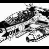
teknos Posted July 16, 2012 Share Posted July 16, 2012 Just to beat a dead horse for no reason, I was considering the problem of not having enough room to rotate the ejection seat and egress from the head when the Valkyrie goes into battroid mode. It seems that one of the primary offenders is the landing gear, according to the wireframes that Dan posted. So my solution would be to "slide" the landing gear assembly forward, into the nose cone/radome (see attached image), and out of the way to create room for the seat to rotate "into". I understand that theres's a radar that's in the way, but couldn't it swing aside to allow for the assembly to slide into the nosecone? And yes, that would also require additional mechanics and linkages, but Robotechnology surely could create something that's wire-thin,...no? This also doesn't solve some of the other problems that Dan's identified, but maybe with enough suggestions and imagination, the seat egress could come a step closer to a functional idea? Just my $0.03 (adjusted for inflation) Quote Link to comment Share on other sites More sharing options...
Kurisama Posted July 16, 2012 Share Posted July 16, 2012 Correct me if I'm wrong - but I'm pretty sure that in the master file there is a diagram showing the config of the cockpit when transforming which shows the landing gear moving out of the bay. Quote Link to comment Share on other sites More sharing options...
MMORefugee Posted July 16, 2012 Share Posted July 16, 2012 Generally, in most aircraft, located behind the radar is the avionics bay, which is chock full of bulky electronics. Even if you were to assume a big overtechnology assist to Moore's Law and substantially shrink the avionics, pushing the gear forward conflicts it with the hip pins. To flog a different deceased equine, I'm on board with Chronocidal with regards to the engine inlets. It would be worthwhile to try a rounded inlet lip with a semicircular cross section. Retain the bulk of the v.1 inlet, but make your airflow happy and laminar, and get rid of those right angles. Quote Link to comment Share on other sites More sharing options...
danbickell Posted July 16, 2012 Author Share Posted July 16, 2012 Yeah, a big part of the Master Files solution was to have the whole nose landing gear bay move outside of the nose (behind it in battroid). Part of what cracks me up about that is they were utilizing the space that the toys have behind the nose in battroid (for the swing bar mechanisms), and that space shouldn't actually be there in the first place! I could go on at length about everything in that scheme that works ok in a 2D diagram, but makes zero sense in 3D, and alters far more about the established design than it fixes by making that battroid seat egress possible. Personally, I think it lessens the design to start moving parts around that shouldn't move. The nose is the central piece of the whole, to which everything else attaches. It really should be a solid piece, not some reconfigurable shell that anime magic happens inside of. It should be a solid framework. The floor of the cockpit and the roof of the landing gear bay are one and the same. Their shapes and sizes are defined by each other. It is part of the frame. It is a bulkhead, with an ejection seat and flight controls attached to one side, and landing gear attached to the other. There isn't even enough room in there to make them into separate volumes that could move around each other somehow (and certainly not without substantially decreasing the sizes of everything contained within). Even if we ignored the issue with the landing gear space, there are still plenty of other space problems with the idea, and it would require throwing out a whole lot of the established design to accomodate this one impossible feature. The cockpit tub would need to be a completely different shape (and this shape is well-defined in the DYRL cockpit side view diagram). The box behind the seat would have to dissappear (or somehow become the battroid screens that magically extend around the seat without decapitating the pilot!). The cavity at the back of the nose (that the head fits inside) would need to be an entirely different shape (than what was shown in the lineart) to allow for some big doorway to open up for the seat to come out of. The outer opening is barely big enough for the seat (forgetting that the DYRL design also has the armrests coming out with the seat somehow, and that a pilot needs to be in the seat and not get his legs cut off), but the inside is much too small. I was watching the TV series over the weekend, and taking note again of how much different the battroid cockpit is compared to the DYRL designs. The TV design is much simpler, but the big caveat there is also how this impossibly big space suddenly exists within the nose somehow. A VF-1 nose is actually very small compared to most fighters. They accurately show this often in fighter, but somehow in battroid there is suddenly this huge room inside that doesn't resemble anything that could possibly be inside the nose. It actually looks a bit like I would expect if it were a live-action show, and they had to build a battroid cockpit set, purposely made over-sized to allow room for lighting and variouis camera angles. As far as the intake leading edges, I'm fine with exploring that. Even the "right angles" that exist in the V1 design are rounded off on on the inner and outer sides already, but I will experiment with rounding them all the way around (so that there are no flat areas left). The trick will be doing this more at the bottom, while the top doesn't change much. As it is in the V1, those flat "right angle" areas at the top edge are really only 30 or 40 degrees off angling straight into the intake interior. I'll see what I can do with it. Quote Link to comment Share on other sites More sharing options...
Kurisama Posted July 17, 2012 Share Posted July 17, 2012 C'mon Dan - being from the games industry, you know how concept artists can just slap down some designs and let the modeller worry about the functionality! I used to always wonder as a kid how the VF-1's battroid cockpit was soooo massive - but it never really bothered me - UNTIL NOW. But yeah - the only way to have the seat swivel and into position with minimum fuss would be to (much like teknos' image) swivel the chair back and slide down slightly - so the back rests ontop of the landing gear - the greeble behind the chair in fighter mode has to transform a little to produce the flat screen TVs too. But in regards to leaving the cockpit in battroid - not sure if possible without it spewing its internals (like a shark does, eww) out of the neck first? Quote Link to comment Share on other sites More sharing options...
nightmareB4macross Posted July 17, 2012 Share Posted July 17, 2012 Hi Dan, PM Sent. Quote Link to comment Share on other sites More sharing options...
danbickell Posted July 17, 2012 Author Share Posted July 17, 2012 Oh, if I had a buck for every time a concept artist gave me a piece of concept art that didn't actually make any sense in 3D... I've tried to teach them how to make plan views of a design and make everything line up between them, but it just slows them down too much and they don't seem to learn. I think spatial perception is just inherently linked with intelligence! The battroid cockpit is certainly more feasible than the battroid seat egress, for sure. The seat doesn't even move that much in the DYRL deisgn. It does not rotate 90 degrees like the TV version does. The head rest tilts back, and the seat rotates back maybe 45 degrees. The pilot has to look up to look forward (and it looks like it would be quite uncomfortable in real life). That is how it would have to be, though. The cockpit tub angles up immediately behind the seat (the deeper portion of the landing gear bay is directly underneath, room for the wheels), so there's nowhere for the seat to rotate back too. The bottom of the seat has to rotate up as much as the top is rotating back. The only way it could rotate 90 degrees and move back (back in battroid) for more space would be if it moved forward (in fighter, down in battroid) first, so that it would lay on the floor. There are big problems with that, though. The the stick and throttle are supposed to pivot up into place for battroid, but the seat would no longer be in the right place relative to them or the pedals. Also, the seat needs to stay where it is because that is the widest and tallest part of the canopy, and there would have to be enough room for the battroid screens to maneuver around the seat and pilot. There already isn't really enough room for this, but if you move the seat forward or backward, this room shrinks. So, you can see why the DYRL design was changed the way it was. It could be made to work, but it certainly wouldn't be very ergonomic. Unfortunately, none of the battroid cockpit screens detailed in the DYRL line art match with anything in the fighter cockpit. To make it work, the box behind the seat in fighter would have to transform into the screens, with arms inside the move them around, and they would need to either be very small or bendable to get between the canopy and the pilot and seat. At some point, I would like to make the DYRL battroid cockpit as a separate model, but I will just model it as designed. Forget about making it actually transform. Quote Link to comment Share on other sites More sharing options...
VF5SS Posted July 17, 2012 Share Posted July 17, 2012 and now you know why they just made the canopy the main screen for the VF-0 :3 Quote Link to comment Share on other sites More sharing options...
Mr March Posted July 17, 2012 Share Posted July 17, 2012 HAHAHAAHA! This reminds me of my father complaining about all the problems he suffered trying to construct an impractical building designed by those "brain-dead" architects I guess some things never change, only the venue does, hehehe. Quote Link to comment Share on other sites More sharing options...
Zinjo Posted July 17, 2012 Share Posted July 17, 2012 The cockpit tub angles up immediately behind the seat (the deeper portion of the landing gear bay is directly underneath, room for the wheels), so there's nowhere for the seat to rotate back too. The bottom of the seat has to rotate up as much as the top is rotating back. The only way it could rotate 90 degrees and move back (back in battroid) for more space would be if it moved forward (in fighter, down in battroid) first, so that it would lay on the floor. There are big problems with that, though. The the stick and throttle are supposed to pivot up into place for battroid, but the seat would no longer be in the right place relative to them or the pedals. Also, the seat needs to stay where it is because that is the widest and tallest part of the canopy, and there would have to be enough room for the battroid screens to maneuver around the seat and pilot. There already isn't really enough room for this, but if you move the seat forward or backward, this room shrinks. So, you can see why the DYRL design was changed the way it was. It could be made to work, but it certainly wouldn't be very ergonomic. Unfortunately, none of the battroid cockpit screens detailed in the DYRL line art match with anything in the fighter cockpit. To make it work, the box behind the seat in fighter would have to transform into the screens, with arms inside the move them around, and they would need to either be very small or bendable to get between the canopy and the pilot and seat. At some point, I would like to make the DYRL battroid cockpit as a separate model, but I will just model it as designed. Forget about making it actually transform. Perhaps that was one of the critical reasons why the subsequent fighters were "larger" than the VF-1. The VF-1 was a compact tough little fighter, but didn't leave much room for even the critical systems let alone upgrades... Quote Link to comment Share on other sites More sharing options...
nightmareB4macross Posted July 18, 2012 Share Posted July 18, 2012 Dan, Have you ordered the 1/24 scale VF-1S head? I'm very curious to see the end results. Quote Link to comment Share on other sites More sharing options...
danbickell Posted July 18, 2012 Author Share Posted July 18, 2012 and now you know why they just made the canopy the main screen for the VF-0 :3 Perhaps that was one of the critical reasons why the subsequent fighters were "larger" than the VF-1. The VF-1 was a compact tough little fighter, but didn't leave much room for even the critical systems let alone upgrades... It can be fun to speculate about in-universe rationalizations for why the various variable fighters are the way they are, but the reality is simply that the VF-1 was the first attempt by some young guys to create a design like that, and they couldn't have had any idea that it would have to stand up to scrutiny from a bunch of nerds like us for all these decades. They clearly learned their lessons though, and it shows all from the DYRL re-design all the way to the numerous variable fighter designs since (even the one that is supposed to be the VF-1 predecessor). It is funny how so much of it came in baby steps, that don't make a great deal of sense in the order they are supposed to be developed. The cockpit displays/battroid screens are a great example. They made the step in DYRL to remove the traditional HUD and replace it with using the whole canopy as a HUD, yet they didn't make the next logical step and use this for the battroid screens (projected lines, reticules, and data on plain old glass was probably as far as their 1984 mind-set allowed). Instead, they designed a completely new battroid cockpit that still has conventional screens, and still didn't make much sense in the space provided. They made the next step with the YF-19's cockpit surrounding displays providing a downward view in fighter that ends up being the forward view in battroid without needing to transform any of it (the seat rotates forward 90 degrees, and all the controls are attached to the seat). Eventually, they come full-circle with the VF-0 battroid cockpit, which borrows from everything learned from the previous designs (previous in the real world, that is) and makes the same type of configuration as the VF-1 actually make sense and work. Makes me wonder what we would see if the VF-1 got another re-design for a modern reboot of the original series. Dan, Have you ordered the 1/24 scale VF-1S head? I'm very curious to see the end results. Yes, I ordered it last week, and just got the email this morning confirming that it went into production. They say it should ship out by the 25th. Being a first-timer with Shapeways, I was wondering if I can now assume if that means that the design has not been rejected, or if it simply means that they are about to try to print it and will reject it if there are problems with the print. I'm real curious to see how it turns out too! I attempted to lay it out in a way that it will only fit in the space of the printer in one orientation, which would be optimal for where the "frosted" areas would end up (the parts that don't come out as smooth, due to contact with the wax support material). However, this could still be completely thwarted by them printing additional orders at the same time (which they reportedly do) if my order isn't on the top of the stack. If that's the case, I guess my only hope is that the printer operator favors the model that is likely more interesting, intricately detailed, and expensive, and puts it on top! I wonder if they frown on people getting around this issue by building a thin frame around the whole thing that takes up the entire printable volume, forcing the desired orientation and making it impossible to print another order on top of it all... Quote Link to comment Share on other sites More sharing options...
Kurisama Posted July 18, 2012 Share Posted July 18, 2012 Yes, I ordered it last week, and just got the email this morning confirming that it went into production. They say it should ship out by the 25th. Being a first-timer with Shapeways, I was wondering if I can now assume if that means that the design has not been rejected, or if it simply means that they are about to try to print it and will reject it if there are problems with the print. It may still yet be rejected, I'm sorry to say - I've been burned twice by this and a few more times by other customers buying my wares - so frustrating as the turn around is SUCH a long time... I hope it's all smoother sailing for you tho. Once u get this sample back - it'll open your eyes as to what detail is seen or produced and what isn't = how much detailing you'll do next time. Quote Link to comment Share on other sites More sharing options...
nightmareB4macross Posted July 18, 2012 Share Posted July 18, 2012 Or how much bigger the scale you have to go with next 1/12? Quote Link to comment Share on other sites More sharing options...
danbickell Posted July 18, 2012 Author Share Posted July 18, 2012 Once u get this sample back - it'll open your eyes as to what detail is seen or produced and what isn't = how much detailing you'll do next time. I do expect to see much of the smallest details lost. Much of the panel lines and such are right around the minimum detail size for the FUD material in this scale, so I'm curious to see what shows up and what doesn't. I have certainly paid attention to your work on Shapeways, and I can already see how how much differently I would approach a project intended specifically for 3D printing in a certain scale and material target, compared to how I've approached this model. Or how much bigger the scale you have to go with next 1/12? In my dreams, that is exactly what I would want to try. The detail would have a much better chance, and there wouldn't need to be compromises for wall thickness. If only volume merely doubled when you double the scale! A head might not be completely out of the question, but the whole VF-1 would cost several thousand $. Quote Link to comment Share on other sites More sharing options...
Recommended Posts
Join the conversation
You can post now and register later. If you have an account, sign in now to post with your account.