Ignacio Ocamica Posted May 6, 2004 Share Posted May 6, 2004 That's it, it's official, time to stop building models altogether. There is no way I could even come close to matching the beauty of your work. What you said Quote Link to comment Share on other sites More sharing options...
Mule Posted May 6, 2004 Share Posted May 6, 2004 William, A technicality: Shouldn't the sweep marks go beyond what you have since the wings fully retract when transformed? All, It is easy to get discouraged when looking at work as good as this, but it also gives you a target to shoot for. I find these threads to be infinitely inspiring and a great source for new techniques. Once you see what is possible, you can just let you imagination run amok. Also keep in mind that William has years of experience, and a lot of this is just a trial and error learning process. Go buy a throw-away kit or two and try a whole slew of techniques on them, and who knows, maybe you could teach William and the rest of us something new. Quote Link to comment Share on other sites More sharing options...
mechaninac Posted May 6, 2004 Share Posted May 6, 2004 (edited) My comment was meant to be facitious; besides, his excellent work is not a discouragement...it's an inspiration. Of course I won't stop trying, but Mr. Cheng does set a rather lofty standard to emulate. Edited May 6, 2004 by mechaninac Quote Link to comment Share on other sites More sharing options...
wm cheng Posted May 6, 2004 Author Share Posted May 6, 2004 Hey thanks all for the kudos! It is always appreciated. Please, I want to see as much modelling going on as possible (of all skill levels). It will get me through the dry patches when I work and can't model (I can live vicariously through you guys ). If anything, I would like to encourage as many people to start or start up again - its a lot of fun especially when you try something out for the first time and it works! I learn so much from all of you - thank you. Part of the reason I share my build ups here is to get feedback - I find I wouldn't of thought of new things to try or details to emmulate if I were to work on my own. Sometimes I find that I get into a rut and like to stay safe (don't want to ruin the precious model - especially when your nearing the end) and only advance when there are problems or errors that I have no choice but to try and solve. I need to see your stuff and learn from you and others - I don't function well as a hermit Especially post problems, maybe we can all help out, but we can certainly learn from them and either avoid them or use the solutions. I love my models so much more after I incorporate all the input I get here on these boards. For those of you following my work, I found that with each model I have improved my skills, if any of you remember my first foray back into Macross (or modelling after a long University/Work break) was that resin VF-2SS which now I am a bit ashamed to put next to my sucessive pieces of work. This VF-0 is definitely my proudest. I love to sketch and paint, so now I feel as though I am doing both on the models I build! Argh!! your right Mule!! @$%! I didn't realize. Well, the wings ARE in - I don't want to risk it by taking them out - its a really tight fit. I would suggest (maybe in my next round when I build another VF-0 again - doubles are really low on my list) at a stage before I glue the top/back fuselage in, I place the wing in the proper position, and lightly trace out the profile/edge of the sweep in both positions (flight mode fully swept and battriod mode full swept) it would be interesting to see a division in the sweep marks. I am definitely going to do it on my next VF-1 (I might do Roy's VF-1S to put beside this baby). Hey Grayson72, I used around 75:25 (Dark Grey: Neutral Grey) - just eyed it. Knowing that I will lighten it up at the end after the decals with a thin coat of the light grey/white I used for the fuselage. The final effect should be closer to the decal grey of the forward part of the ventral fins and the grey patch where the swing wings sweep. Hey David, I don't really do anything special gluing the landing gear parts. Although I am going to try using crazy glue (instead of cleaning off the paint and using regular glue) this time around. I just hold the gears straight until they set. I usually wait till the gears set before I glue the tires on - that way I glue the tires and set the plane on them - it kind of self levels. I put something up against the front double wheels against each wheel on both sides so that they don't splay out due to the weight. Well, I'm off to do the landing gears, and maybe if there's time, un-cover the canopy!! yaaa! Quote Link to comment Share on other sites More sharing options...
David Hingtgen Posted May 6, 2004 Share Posted May 6, 2004 Yargh, I didn't consider that VF's have "ultra-oversweep" either. Well, maybe you can just explain it away that a VF-0 will probably sweep the wings in fighter mode a lot more often than going from fighter to battroid, thus only the "normal" sweep area would show noticeable wear. Currently working on my Blue Angels Hornet. Nothing like a gloss finish to make you get all the seams and stuff SMOOTH. And no belly tanks and weapons to help hide anything!!! (Ironically, I seem to have gotten the gear doors quite glossy, better than I can get on a model car! ) Quote Link to comment Share on other sites More sharing options...
wm cheng Posted May 6, 2004 Author Share Posted May 6, 2004 Here's a shot of the landing gear doors crazy glued in. The forward doors fit really well - almost snaps into the indents Hasegawa provides. The rear doors don't really fit that well. The big square holes are nice, if only there were equally big square pegs to go into them! Unfortunately, the gluing surface is only at the edges of the body panels, so not too much holding them on there. We'll see if the crazy glue is any better than normal glue at these doors - its faster though, but I doubt that they would hold up better. Quote Link to comment Share on other sites More sharing options...
wm cheng Posted May 6, 2004 Author Share Posted May 6, 2004 I also glued the gears in, paying careful attention that the forward gear is perpendicular, and that the rear gear hubs are perpendicular (the rear gears should splay out a bit). Quote Link to comment Share on other sites More sharing options...
wm cheng Posted May 6, 2004 Author Share Posted May 6, 2004 I added a drop of white glue to the landing lights - it should dry clear, and I would dab it with a bit of future once dried. Quote Link to comment Share on other sites More sharing options...
wm cheng Posted May 6, 2004 Author Share Posted May 6, 2004 I finally took off the mask and canopy. I carefully sliced the mask and fuselage all the way around to break the seal first - this helps eliminate any chance that removing the canopy can tear away at the paint. Quote Link to comment Share on other sites More sharing options...
wm cheng Posted May 6, 2004 Author Share Posted May 6, 2004 I also positioned the airbrake - I glued it in with this WeldBond white glue, its somewhat elastic when it dries, and it dries clear. It gives some work time unlike crazy glue, so I can properly position the brake to make contact with the two actuators. Quote Link to comment Share on other sites More sharing options...
wm cheng Posted May 6, 2004 Author Share Posted May 6, 2004 Funny, when I removed the brake, there was all this dust and debris that had blown in through the holes. I had to give that area a good scrub with an old toothbrush before I glued the actuators in. I just love that Tamiya marker on the bare metal portion of the actuators, I just wished it came in paint form. Quote Link to comment Share on other sites More sharing options...
wm cheng Posted May 6, 2004 Author Share Posted May 6, 2004 Okay the wheels. I needed to give the edges of the wheels a good sanding, there is a seam running right down the tire portion of all of them. Quote Link to comment Share on other sites More sharing options...
wm cheng Posted May 6, 2004 Author Share Posted May 6, 2004 Everyone always ask how to paint the tires with a good separation between the hub and rubber. Well, a lot depends on the molding of the kit and whether they molded a strong line separating the hub and rubber. I usually paint the hub first, and do a light grey oil wash to pick out the details. Then I use a black gundam marker and trace the line separating the hub and rubber - usually if the seam is deep enough, the pen (or you can use a Micron 005 pegment fineliner) tip just falls into the groove. Now when you paint the flat black, you don't have to paint right up to the hub, just paint up to the black. All the blacks blend together anyways. Quote Link to comment Share on other sites More sharing options...
wm cheng Posted May 6, 2004 Author Share Posted May 6, 2004 Here's the shot done with the flat black paint. Once its dried, I rub it a bit with my fingers to get some of my natural oils on it, it gives the flat black a bit of a sheen that really looks like rubber - plus it blends where the marker and flat black separates - the marker is a bit glosser. Quote Link to comment Share on other sites More sharing options...
wm cheng Posted May 6, 2004 Author Share Posted May 6, 2004 I also hand painted the lighted areas silver first, then after that was dried, I painted over that with clear red - the silver makes it reflect better. Quote Link to comment Share on other sites More sharing options...
wm cheng Posted May 6, 2004 Author Share Posted May 6, 2004 I dipped the canopies in future floor polish and let it dried. I then painted the edges and inside rim in flat black. Since I was going to display this bird with the canopy up sometimes, its pretty important to paint the interior flat black, only the exterior frame is provided in decals. Which would be one of my last steps tomorrow - along with glueing that lower pilots tube back on (arggh ) Quote Link to comment Share on other sites More sharing options...
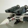
wm cheng Posted May 6, 2004 Author Share Posted May 6, 2004 A parting shot till tomorrow. Quote Link to comment Share on other sites More sharing options...
J A Dare Posted May 7, 2004 Share Posted May 7, 2004 Wm, you're going to be a legend in Macross fandom lore. And someday in the distant future, I'm going to have the satisfaction of tell my grandkids that I watched him do his magic. Hey you graphic designers, start thinking about wallpaper concepts! Quote Link to comment Share on other sites More sharing options...
dyowelb Posted May 7, 2004 Share Posted May 7, 2004 Wm, you're going to be a legend in Macross fandom lore. And someday in the distant future, I'm going to have the satisfaction of tell my grandkids that I watched him do his magic. Hey you graphic designers, start thinking about wallpaper concepts! you;re wrong...he is already a legend here in MW.... Quote Link to comment Share on other sites More sharing options...
bhop Posted May 7, 2004 Share Posted May 7, 2004 I love your models, and pretty much feel like you're my aircraft modeling hero. Your stuff always seems so perfect when complete. There is thing that nearly ruins it for me though, and that's the perfectly round tires. It just kills the scale to see all that weight sitting on the tips of perfectly round tires when the weight of the plane should be pushing the tire down. (just look at your car for a real life example) or here's a pic to see what I mean on a real plane... Quote Link to comment Share on other sites More sharing options...
David Hingtgen Posted May 7, 2004 Share Posted May 7, 2004 (edited) Well, IMHO 99% of modelers severely overdo tire flattening/bulging, more so over-weathering. Better to have none, than make it look like it's 50psi underinflated. Of course, all you need is a nice flat surface and a big sheet of sandpaper, and you can flatten rather easily as the very final step. BTW--is that an F-14D®? Glove-vane area looks too nice for any A/B, but too distinct for a new-build D. ::edit:: Why can't I make a capital "R" in parentheses? It keeps substituting a "registered trademark R in a circle" instead. I want F-14D with "an R in parentheses after it", for that's how it's written. Stupid "auto-spelling" etc. I want what I type! Edit 2. Anyone know how to actually type a capital R in parentheses and not have it show up as ® ???? Edited May 7, 2004 by David Hingtgen Quote Link to comment Share on other sites More sharing options...
Sam Posted May 7, 2004 Share Posted May 7, 2004 Thats beautiful. its a wonder you arent a commission worker for making ppl models. Im sure there would be plenty of ppl that would pay you for work like that that wish to have such quality. You can have a most enjoyable work option that way! I must confess i tend to be inspired, then shattered, inspired, then shattered, beholding the mystic works of William.*sigh* I picked up some of those pastel pencils against the day I make my next valk Sam Quote Link to comment Share on other sites More sharing options...
Jawjaw Posted May 7, 2004 Share Posted May 7, 2004 MW seriously needs its own gallery for wm_cheng's work. I want to see tons of pics of this beauty when it is done. Quote Link to comment Share on other sites More sharing options...
bhop Posted May 7, 2004 Share Posted May 7, 2004 Well, IMHO 99% of modelers severely overdo tire flattening/bulging, more so over-weathering. I do agree with you there, that it's overdone a lot of times. I just think it's a shame for such flawless work otherwise to miss this tiny detail, tiny as it is, it can add a lot to the realism. (and I do consider WM's work to be flawless..dang, it's awesome.. ) Quote Link to comment Share on other sites More sharing options...
Grayson72 Posted May 7, 2004 Share Posted May 7, 2004 that resin VF-2SS which now I am a bit ashamed to put next to my sucessive pieces of work. Heh, yeah that was some serious panel shading you did on that one Quote Link to comment Share on other sites More sharing options...
wm cheng Posted May 7, 2004 Author Share Posted May 7, 2004 Argh, my brush painting skills suck! The black on the tires didn't turn out as smooth as I thought it would - so I stripped it and plan on redoing it. While its naked again, I thought I'd try my hand at flattening the bottom of the tires. My biggest worry before is that the flattened bottoms won't sit perfectly to the ground. I don't think that running the entire model on a flat piece of sandpaper with the wheels on will do it either, since I think the landing gear struts will just snap off due to the lateral shear forces. The best way I can think of is to sand the tires while they are off (pictured here in my vise), with a hard/rigid sanding block (to get it perfectly flat) then put the tires on and rotate them to land flat once they are on the gears. This assumes the rear tires don't have much of a camber (unlike F-16s). If there's a better way to do this than I would really like to know. And of course - re-paint Quote Link to comment Share on other sites More sharing options...
wm cheng Posted May 7, 2004 Author Share Posted May 7, 2004 The canopy is done! I'd suggest not using any MicroSET or SOL or any decal setting solution - and getting the entire area really wet - since you need a fair bit of play time to get these intricate shapes into place. Luckily for us and thanks to Hasegawa - they fit perfectly. I'd wish they do it for all their kits - I've been spoiled - I've never been very good at painting these canopy frames. The way they broke down the pieces is perfect - otherwise it would be too difficult to get one big piece to lie down properly. I just can't get over how happy I am with these canopy decals. Quote Link to comment Share on other sites More sharing options...
wm cheng Posted May 7, 2004 Author Share Posted May 7, 2004 Okay, here's a shot with the canopy open. Just ignore the first part of this thread about making those damned canopy hinge - ahh, it just doesn't really work. The metal pin just doesn't have enough of a contact area to the canopy so the joint is just too delicate to take any serious force. As a result, the two pressure plates hidden behind the cockpit bulkhead needs to be pried apart so that it doesn't exert too much pressure on the metal rod to cause it to snap off the canopy. But since there is little or no pressure, the canopy doesn't stay up on its own. It looks like you should just decide early on whether to build this bird with the canopy up or down (Man I hate this!!) If anyone knows of any way around this - I'd really like to know. Does anyone make any really small hinges. This and doing the plane with the gears up or down is always a problem for me every time I approach a model! Quote Link to comment Share on other sites More sharing options...
wm cheng Posted May 7, 2004 Author Share Posted May 7, 2004 Here's a closeup shot. I ended up needing to build a "prop" to hold the canopy up in position. Luckily there was so much "gak" in behind the pilots seat that I could just jam a piece of wrapped wire (you know those twisties that hold a toy in its packaging) and it stays wedged in. I stripped the top portion of the wire, so it looked like an hydraulic actuator. It looks kind of cool, but I'd need a tweezer to remove it whenever I decide to have the canopy down. Man, I must work in a really dusty environment (my basement) - I am starting to notice a few little tiny fibres or dust that got trapped under my clear-coats (current count is 3 small fibres about 1/16-1/8" long). Luckily its not in the obvious places. Better not look too closely I hate it when I am almost finished, when I start to really inspect the hell out of it - and you start noticing little flaws. Quote Link to comment Share on other sites More sharing options...
mechaninac Posted May 7, 2004 Share Posted May 7, 2004 (edited) About flattening the tires: Have you tried using a hot knife, or better yet an old clothes iron (better heat control), to deform the tire just enough to make it look like weight is sitting on it. Sanding a flat spot won't create a bulging effect, but heat deformation will, though on a 1/72 plane that distinction may be moot. Just secure the wheels with the tires or the tires alone to a rod of some kind and press them against the hot surface just enough to soften and flatten the plastic...think of it as a variation on the sprue heating and pulling technique for creating antennas and such. My only advice if you decide to use this method would be to try it out on a spare part to get a feel for how much heat and pressure you'll need. Edited May 7, 2004 by mechaninac Quote Link to comment Share on other sites More sharing options...
David Hingtgen Posted May 7, 2004 Share Posted May 7, 2004 There's always the frying pan/baking sheet method for getting flat tires. I swear it's considered a legitimate method, though I don't have the guts to try. Would actually probably be the easiest, just use LOW heat. I do think they recommend non-stick ones. Quote Link to comment Share on other sites More sharing options...
tetsujin Posted May 8, 2004 Share Posted May 8, 2004 If anyone knows of any way around this - I'd really like to know. Does anyone make any really small hinges. I've made some rather small hinges in the past, as I wanted to make better-detailed replacements for my PG Zaku hands: http://1-4-4.home.comcast.net/models/Proje...nstruction.html The hinges I made for the fingers had four basic components: the center hinge pin wire (made of soft 1mm flower wire), the hinge wires (eyelets which fit tightly around the hinge pin, made by hand out of steel sewing pins), the cosmetic resin covers for the hinge pins, which gave the hinge its desired spherical shape, and the finger segments in which they were installed, which helped to keep the hinge halves together. Offhand I'd say these hinges would still be too large: they're based on an axis of 1mm flower wire, with steel sewing pins bent around it to form the hinge parts. For the Zaku hands the entire hinge was encased in a 3mm sphere. But I don't think you want something like that sticking out of the fighter canopy. But here is a basic approach I would take if I were to attempt a canopy hinge for this kind of kit: 1: Anchoring the hinge to the canopy Epoxy, super glue, whatever, are no good. They'll pop right off if there's any stress. The only option IMO is to drill into the canopy and have a piece of wire from the hinge extend into the canopy. If the drilled holes go into the part of the canopy (frame) which is painted-over, then none will be the wiser. 2: Basic hinge design When the canopy is closed, you want the canopy to sit in just the right place - and yet, you also want it to be able to open. This is a bit difficult to do directly with a single-axis hinge, generally the hinge would wind up in the wrong place because of the scale you're working at. So it's best to do something like this with an extending hinge-joint of some kind: either a double-hinge that "folds" when the canopy is closed, and "extends" when it's open to give the canopy more clearance, or some kind of linear extension. Also, you have to consider whether you can actually make a load-bearing hinge at this scale, and if so, how much difficulty that adds to the project, and how much risk of future breakage. Load-bearing hinges at this scale are not impossible, but I can tell you from experience that they're pretty hard. A simple alternative might be to attach a strut to the canopy: when the canopy is opened, you could place the strut onto a strategically positioned support inside the cockpit, and maybe pass this strut off as some kind of hydraulic or something. Suggested designs 1: Hinge the canopy with sewing pin-over-flower wire. Mount it to the canopy by drilling into the canopy and plugging in the sewing pins which extend from the end of the hinge. This design is probably closest to your original aim: to have a self-supporting, unobtrusive hinge. The hinge design and installation you use may determine whether the hinge would need to be embedded in resin, or if having just the wire-on-wire would be adequate. Note, however, that the holes for the sewing pins into the canopy will be difficult: in order for them not to be seen, they must angle off in the direction of the canopy frame, but to connect to the hinge properly, they must go straight backward once clear of the canopy. This bend must be performed before installation or you will break the canopy. The flower wire which serves as the hinge pin could also extend backward, to be the mounting of the hinge into the plane. If the flower wire is embedded into a drilled-out polycap or bondo, then it could slide inward and outward, providing the extension you need to cleanly open the canopy. 2: As above, make holes into the canopy to accomodate steel pins: however, instead of having the steel pins also be part of a wire-on-wire hinge, have them extend into a hinge system hidden behind the cockpit. This hinge system could be larger, and more conventional, but because a larger hinge like that wouldn't be on-axis with where the canopy should really be hinged, it would have to be a little bit more tricky, too. One design that may work: when the canopy is closed, the wires extend straight back from the inner top edge of the canopy, and tuck in between the back wall of the cockpit and the nose area which surrounds the back of the cockpit. To open the canopy, the back wall itself would slide or tilt forward, exposing a hinge to which the canopy wires would be mounted. In practice, the action of opening the canopy would be a bit fiddly and both motions would need to be more-or-less simultaneous. However, there are quasi-small hinge parts you could use to make the rest of the hinging work easier: something like a Wave T-Shaft would be small enough to sit behind the rear wall, probably have enough resistance to hold the canopy in place, but not so much resistance that moving the canopy would wreck your installation. If you decide to go the wire-on-wire route, well, there are some advantages and some disadvantages to this. An advantage of the flower wire is that it's kind of soft, so as you work the joint it becomes a better custom-fit. The Steel pins have a bit of springish yield when they're in the eyelet shape around the flower wire, too. This makes it possible for the hinge to have some "sweet spots" where it will prefer to sit - the tradeoff being better load-bearing in exchange for less choice of what position the hinge sits at. Probably the best way to manage that would be to create the hinge, identify its sweet spots, and adjust your installation so the sweet spots are in favorable orientations. It really is possible that such a design could work with no resin involved, since the hinge doesn't have the same constraints as my finger joints. A disadvantage is that it's tough to build those little eyelets. The eyelets need to be planar or they'll form little screw-threads on your hinge pin (which isn't as serious a problem for this application as it was for the fingers.) And most importantly, they need to be tight around that flower wire, or the hinge won't be properly load-bearing. Anyway, if you're interested in trying this and need better descriptions of how it works, let me know. It's hard to explain this stuff. Quote Link to comment Share on other sites More sharing options...
bhop Posted May 8, 2004 Share Posted May 8, 2004 (edited) Man.. this is my favorite piece from you so far. I may not post much, but i've followed most of your buildup threads. This model is proof that practice does help. You just keep getting better. Anyways.. For the tires, i'd just sand it a little at a time and occasionally set the tire on a flat surface to test it out. It's best to do too little than too much. Once it's on the plane you may have to touch it up a bit. I actually used this method on my own VF1A. I think it worked out ok. Edited May 8, 2004 by bhop Quote Link to comment Share on other sites More sharing options...
Grayson72 Posted May 8, 2004 Share Posted May 8, 2004 Man.. this is my favorite piece from you so far. I may not post much, but i've followed most of your buildup threads. This model is proof that practice does help. You just keep getting better.Anyways.. For the tires, i'd just sand it a little at a time and occasionally set the tire on a flat surface to test it out. It's best to do too little than too much. Once it's on the plane you may have to touch it up a bit. I actually used this method on my own VF1A. I think it worked out ok. Nice dio bhop, looks good. Quote Link to comment Share on other sites More sharing options...
Akula Posted May 8, 2004 Share Posted May 8, 2004 yea, I'd love to see the rest of it... Quote Link to comment Share on other sites More sharing options...
Recommended Posts
Join the conversation
You can post now and register later. If you have an account, sign in now to post with your account.