wm cheng
-
Posts
4311 -
Joined
-
Last visited
Content Type
Profiles
Forums
Events
Gallery
Everything posted by wm cheng
-
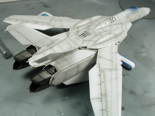
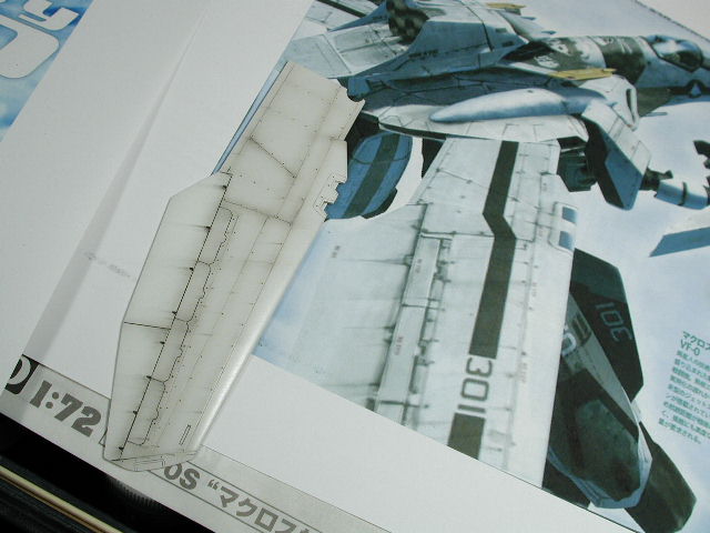
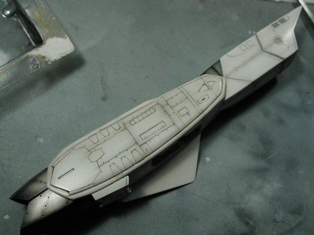
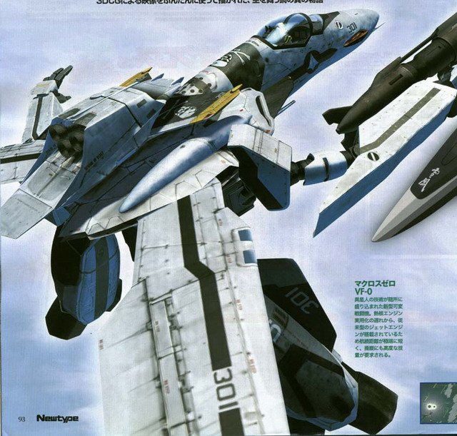
Well there it is - I just repeated the above process all over the aircraft, trying to duplicate the CGI reference where I could. Actually, the photos looks light, its actually more heavily weathered than this. I post the reference I used below this image.

-
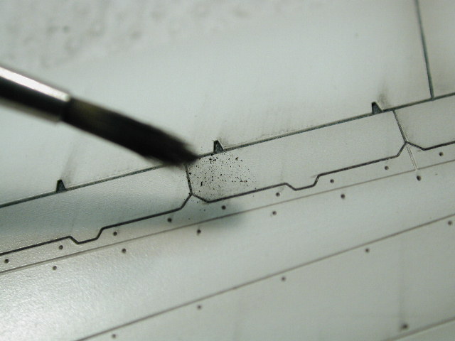
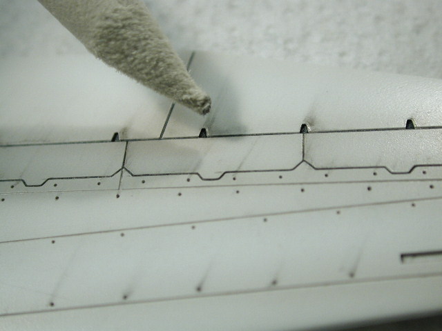
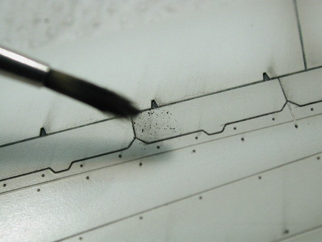
I noticed that on the CGI model, there are darker spots in the panelling especially around certain junctions where a few panel lines meet. I use the shavings and dab a dry brush into it and work the dust into the areas lightly where I want it to be darker.
-
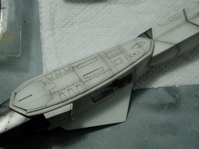
I then used the smudge stick / shader to smudge the drawn oil streaks in the desired direction - then I use a paper towel to also wipe in the same direction. If I had to much, I would rub it with a damp paper towel or use the kneadable eraser.

-
Specific leaks I drew on lightly - I took David's suggestion and made the leaks in the direction of airflow when the wings are fully extended. This is a comprimise, since the CGI model (believe me I've looked carefully) wings streak at a nearly perpenticular angle to the trailing edge of the wings (not even fully extended would the airflow be in this direction!)

-
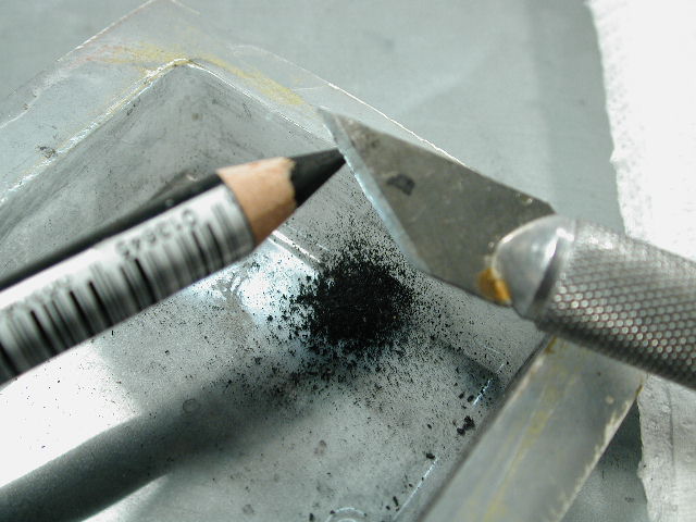
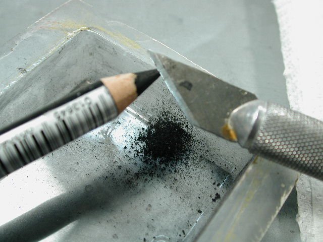
I use an xacto knife to scrape away at the pencil to create shavings/dust in a plastic container (battery packaging bubble) that I can brush on for general darkening not specific leaks.
-
How's this - its actually a bit more heavier in real life, the camera misses some of the finer details - its a bit odd every takes on a warmer tone.

-
Then used a paper towel to wipe in the direction of airflow which blends it in and creates the faded tail. I also wiped some in the vertical direction top to bottom on the service hatches to simulate leakage during flight operations on the ground. I experimented on this inside part of the leg first - since you don't really see much of it when its glued in tucked beside the arms.
-
I just lightly drew some oil streaks in the direction of airflow.

-
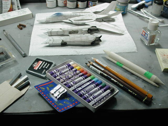
Ok, shortly thereafter... and $32 poorer, we get our supplies. Man its been a while since I bought skteching supplies. I didn't want to make the trip back so I bought a little of everything that might work. Starting from the left working our way right: 3 sticks of conte, a rectangular kneadable eraser, pencil sharpener, oil pastels, 3 pastel/chalk in pencil form, and a thin and fat shaders. I'm kind of excited about the pencil pastel/chalks, it allows precise control (literally we can draw the oil streaks on) and can be smeared with the shaders/smudge sticks (essentially paper compressed and wrapped into a tube with a sharpened end). Well, the oil pastels were totally useless, they were too oily to be shaved into any type of fine particles to be used. But my gut feeling on these pencil pastel/chalks worked. I included white in purchases since I need to weather down the black talkfins and markings after I apply the decals.
-
Argh! it didn't really work - the chalkiness of it wiped off too easily You hardly see it, and with any further handling (even just to get a clear-coat on to protect it) it just about dissapears. Oh well, please bear with me as I experiment on this phase. I think its off to an art store for some supplies...
-
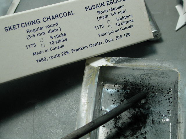
Hey LTSO, my brakes came out fine, I use Tamiya masking tape, which helps - I also don't leave it on too long or press too hard. What is your white undercoat - I find that really glossy finishes tend to mar slightly with the masking tape - or anything else for that matter. Thats why I like working with semi-gloss finishes - its seems to be more resistant to abuse. Funny you should mention being based in a coal mine David I thought I'd try sketching charcoal, I used an xacto knife to scrape away some filings to dab onto the plane.

-
Wow, thanks David, what fantastic articles - now I have something to aspire to. I've always loved that mottled grey look, now with that weathing tip, I can finally start on that 1/72 F-14 (if only I had the time). I will try to adapt those tips to this VF-0, except it should be a little more weathered than real-life, since I want it more animation/cgi accurate. This would be a good test bed for the F-14 later on. However, I don't have the skills or control of do those panel mottling details on a 1/72 scale. My wife would kill me if I started building 1/32 planes!! Also, I don't want to turn the VF-0 grey, it is essentially a white plane with streaks. I'll omit the mottling this time around, and concentrate on the streaking and same colour over coat to blend it in, but I might try some mottling then in the over coat when blending. Oh, well, I'll revise my previous estimates, the post-shading that you guys saw represents 25% of the finished product. Thanks Graham, I meant the two bulges on the top of the plane on the "front/back" plate. I think they are optional, since there is very good panel line detail underneath them on the Hasegawa model (just that we've never seen a VF-0 without them). I'll try to post some pictures of the pastel streaks later today.
-
You said Noel! (although if I go through the effort of customizing, maybe Hasegawa will speed up the process and put one out before I'm finished ) Bitter? me,... non! I'll be looking forward to that baby!! Hey, even the "pros" didn't fill in the injector pins/holes in the landing gear doors, they left some and covered some up with some piece of styrene - man, no respect!
-
Hey here's another reference on the weathing - look, the streaking is definitely not in the direction of the airflow - pretty dirty bird if you ask me How would I attempt to get that surface mottling - I see a lot of recent tomcats like that, its more than just paint patches?
-
Oh, sorry Hikuro - didn't mean to ignore your question, but I'm not sure I understand the situation. (you know, you should strip paint with the solvents instead of sanding it off). If my read is right, you sanded the paint, but that left the old paint in the engraved panel lines showing through - and you are asking if you can still do the oil wash in the panel lines to show up? Well, that depends on how much of the engraved lines are still a recess after they have been filled with your old paint. If you stripped the paint with a solvent (one that doesn't eat at plastic) and a toothbrush, you could get all the paint out of the crevices and that would leave deep enough engraved troughs to hold the oil wash details. If the paint in the panels have filled the tiny lines then no - the oil wash would be useless since there is really nothing for the oil to sit in.
-
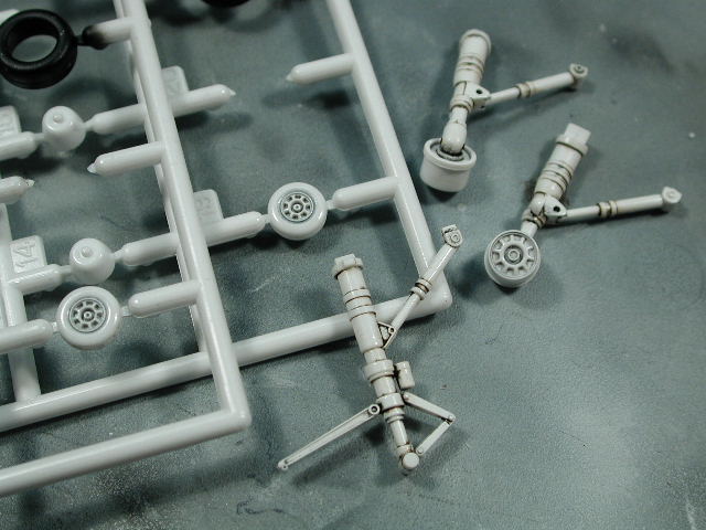
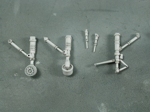
I sprayed the front wheels white and applied the dark wash on them to pick out the details. Actually, I applied the wash first thinking I'd be lazy and use the white plastic of the wheels as is - but it looked plasticy translucent. So I painted over it, and it was good since the original wash was a bit too dark. The trick to doing these wheels and getting a good separation between the white hubs and the black rubber is doing this black wash, the wash gets into the crevice between the hub and plastic, then when I hand brush the flat black on the tires, I don't have to go right up to the edge of the hub, I let the black oil wash do that for me.
-
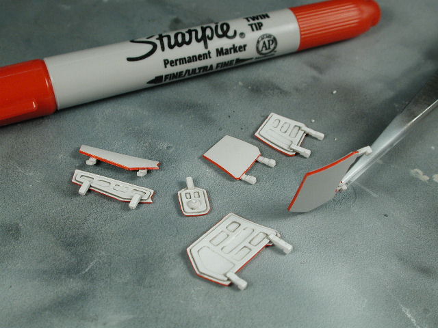
Here's the doors edged in red, I love this Sharpie marker (you can get them at most Staples or Business Depots) it has two ends, a fine and broad tip. The hardest part was continuing the red edge pass the hinges, I had to scrape some of the paint off to eliminate some excess red on the hinge tabs.

-
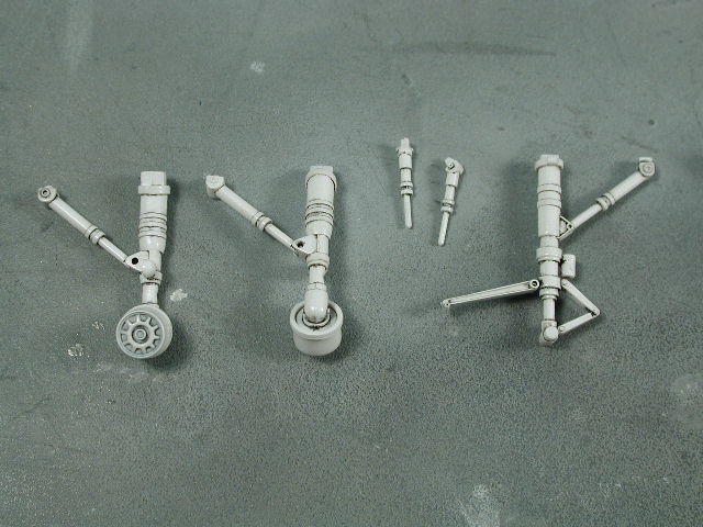
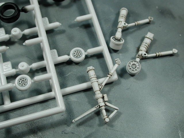
A black wash on the landing gears to pick out some detail, I'll do a brown rust/hydraulic leak wash afterwards. Another great Hasegawa innovation, the rear main gear hubs are molded separately from the tires, hallaluah!! Too bad the front gera wheels aren't like that too. By the way, that can on the front gears, is that the brake fluid reservoir? What colour should it be? I still need to apply the Tamyia chrome maker to the bare metal actuator struts.
-
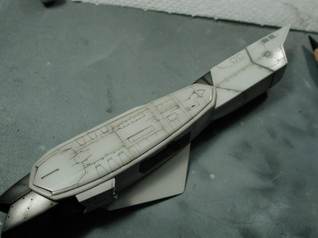
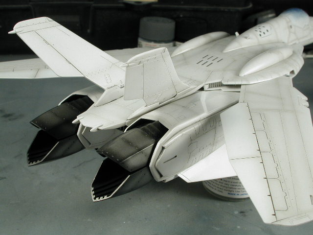
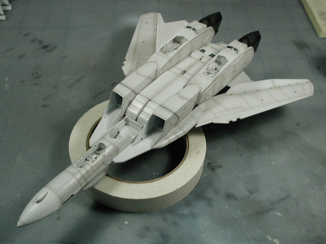
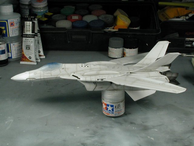
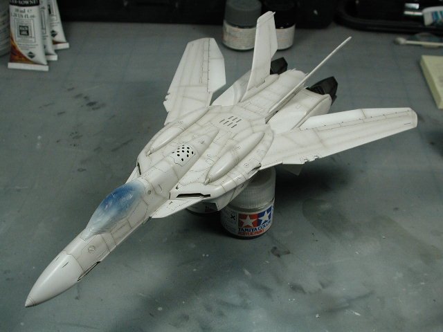
A profile shot...
-
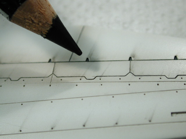
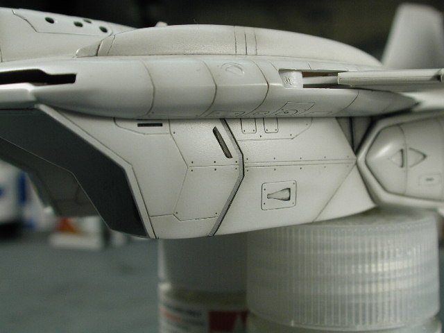
Man I love the tailcones, thanks for the idea to do the ribs - I love them. I also drew in some pencil lines on the top part of the leg to restore that ridge that kind of gotten lost in all that sanding and defined some very light panel lines. The pencil lines are sealed in under the clear coat to prevent them from being rubbed away.
-
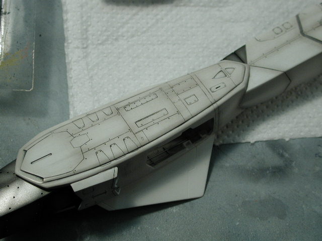
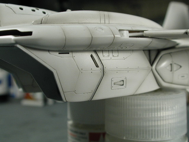
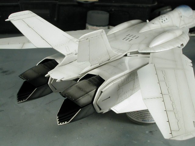
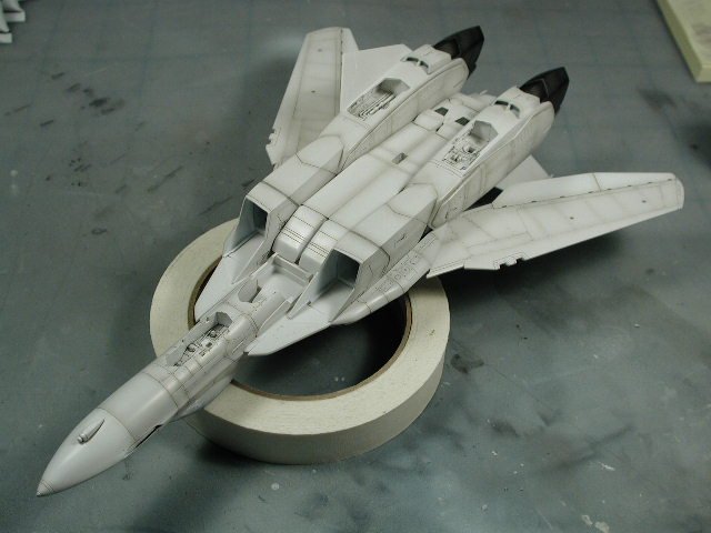
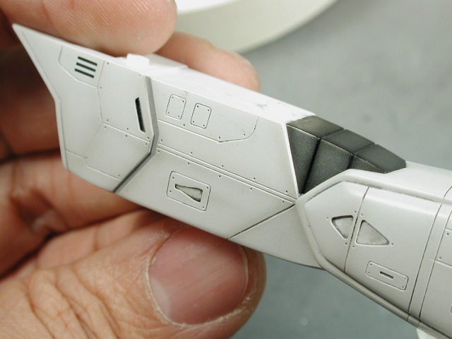
A close up of the intakes with the grey painted separation at the hip.
-
Here it is drying after another clear-coat to protect the very fragile and thin post-shading work. I highly recommend a clear-coat after the post-shading, since often its just a light dusting of paint, it can scratch off.
-
Unfortunately during all the handling, I tore off that nose pilot tube. I knew it was going to happen when I glued them on in a much earlier step, but I had to do it early on since I wanted a good bond between the plastic (before it was painted) and I wanted an oil wash and post-shading to occur at the valley where the probe meets the radome. It was a hard decision back then, normally I always leave the fragile things till the very end, but they always looked tacked on, and often fell off since it wasn't properly glued in the first place (worst, often it would ruin the painted surface or take some paint with it when it fell off). I don't think I have a single model that has a pilot's tube intact
-
I masked that hip separation and painted that sky grey to give it a little more definition than just a oil wash.
-
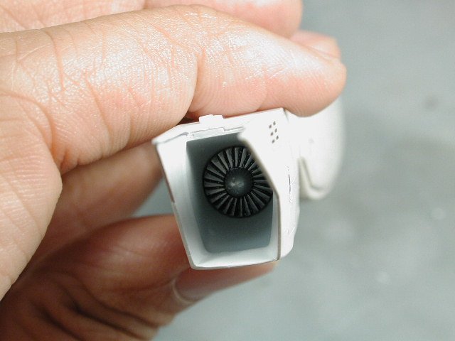
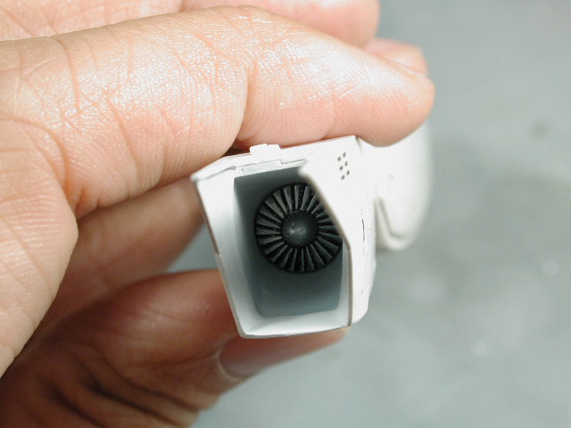
The front intake turbines, I cut to two little pins off, its too difficult to align them properly. Its too bad they didn't set it back further into the intake.