wm cheng
-
Posts
4306 -
Joined
-
Last visited
Content Type
Profiles
Forums
Events
Gallery
Everything posted by wm cheng
-
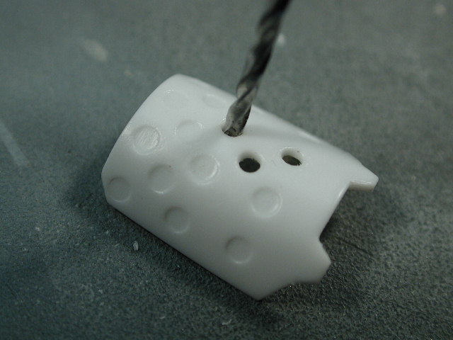
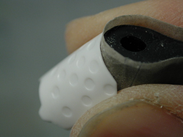
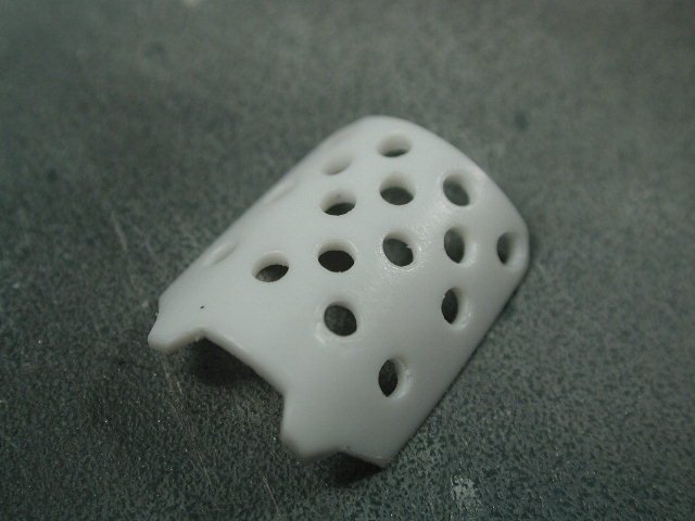
Here it is with the holes finished, I used a slightly larger bit to finish them off more as a reamer to finish the sides. I am glad that I did not thin the piece down in the beginning - it would be too fragile. The holes are small enough that the edges showing do not bother me as much. Please take care at the two last corners, as the holes are really close to the end corners of the brake.
-
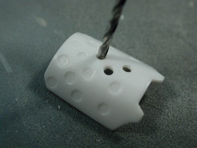
Here I started with a smaller bit first - its important that you don't try and force it, just gently ease the pin-vise bit through. The more holes you drill, the more fragile the piece becomes. I always try to drill directly perpecticular to the hole.
-
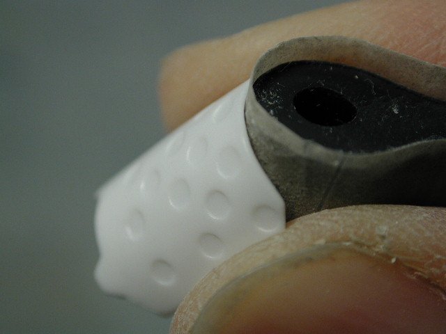
I've been look forward to this for weeks. The airbrake, I would suggest thinning the sides by sanding the edges at a 45 degree to make the edges look thinner - more in scale with the sheet metal of the plane. I had thought about thinning the entire brake down since I'd be drilling holes through it so you would catch the edges in every hole and the thick plastic would be a dead giveaway - but I was worried that would serious weaken the plastic. Its six or 1/2 dozen or another... so I chose the safe and easy route and just thinned the outside visible edges. For the truely insane out there, I suppose you could manufacture this item with a thin bent sheet of metal to get the right thickness I'm not there yet. (yuck! I think I need a manicure )
-
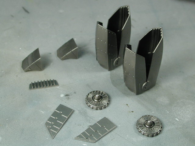
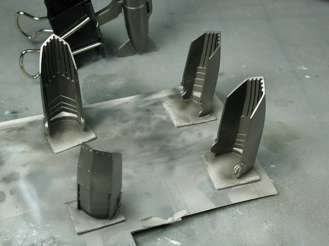
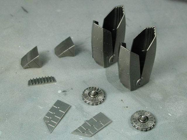
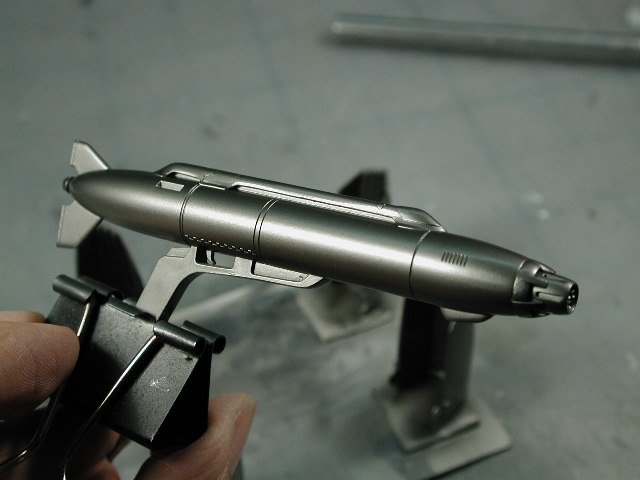
Some more metallic parts...
-
The gun achieved a almost mirror like metallic finish without buffing or sealing.
-
I took a little time out to paint the metallic steel parts. Man its been a while, I forgot to prime first - and with this Alcad metallizer stuff, you really need to use their excellent primer. Its wierd especially with metallic paints all the imperfections in the molding of the plastic that comes through. I had to prime over top of the painted surfaces and re-spray the metallic steel colour. However, this finish is so much more satisfying that the Tamiya metallic grey or steel. Just make sure you wear a mask when spraying, this laquer stuff especially with metallic particles suspended in it can't be healthy for ya!

-
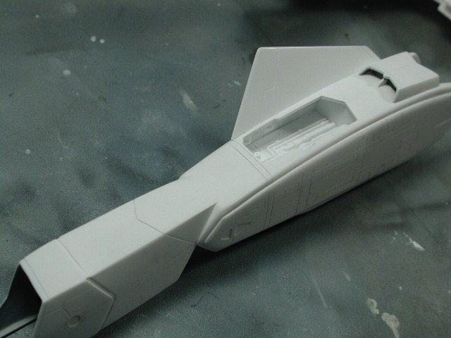
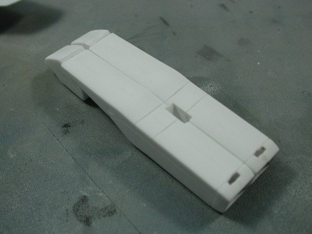
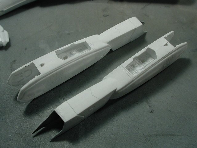
The top also turned out okay now (after several tries)- unfortunately I sanded so much that I sort of lost the faint small rectangular panels on the top surface. I would recommend that you glue this top piece onto the legs right away and start filling and sanding with the seams of the legs, that way it's easier to maintain the same slightly ridged profile of the leg.

-
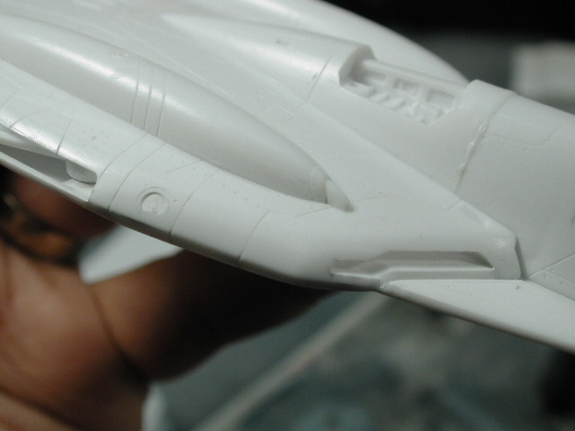
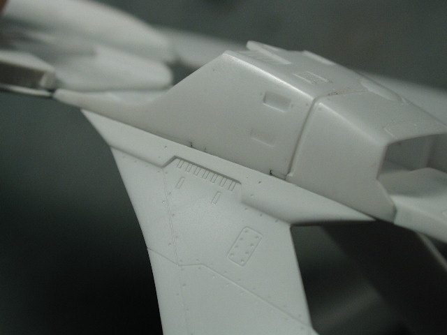
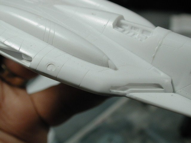
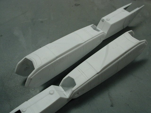
The leg turned out okay as well after I re-sanded several times, the panel lines continue across the seam to my satisfaction, and the re-scribed intake lip turned out okay too. I should of thinned the forward leading edge of the walls of the rear intake by the feet - here's a tip for others The thick plastic walls always make the model look toyish.
-
This rudder seam turned out okay after more sanding and filling.
-
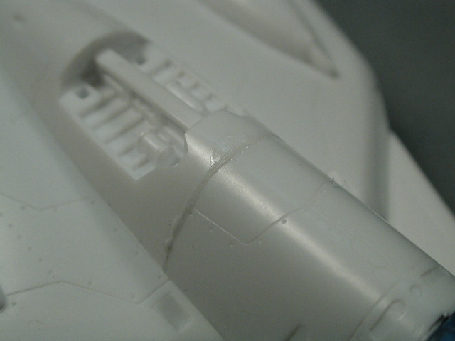
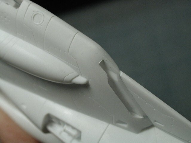
ARRGH!! I'm having bad luck with this bird! I don't know if its me or the kit, but I was hoping that this VF-0 would be like the previous VF-1 where the nose section fits almost seamlessly to the fuselage. Unfortunately, when I slide the nose on, it tends to droop down creating a rather large crack here (it may be that I glued those forward leading edges at a slightly downward angle). So I guess I would have to glue this piece on now so I can do any sanding or repair work before I give the bird a first coat. Unfortunately, to close up the gap, I needed much more glue than I applied (I applied very little at first - wanting to leave the seam as a panel line) - but it wasn't enough to hold close the seam. As a result, I had to pry it apart again, and drop in a bit more liquid cement in the seam - unfortunately I think I added too much, because when I closed up the seam, it all oozed out the sides and gave me this mess. I'll let it dry and sand it flat I hope - I may re-scribe that line in after, but I must have the patience to let it dry completely. Nothing worst than trying to sand away liquid cement excess when its not completely dry - what a mess!
-
Again, another crucial joint, finally in the right profile, its too easy to sand it flat - but I think it looks better angular but not sharp.
-
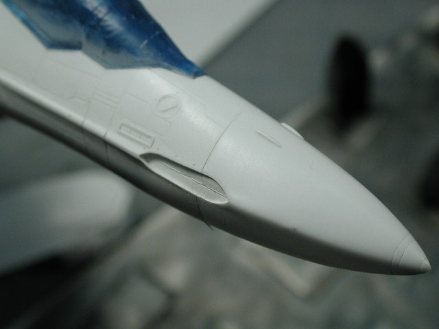
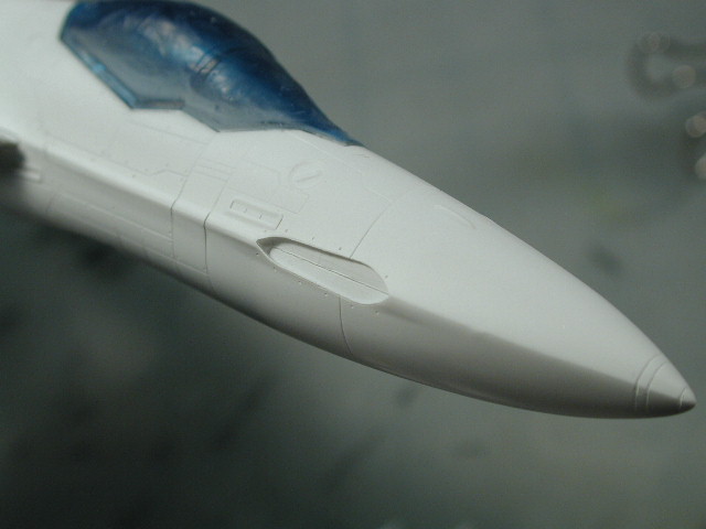
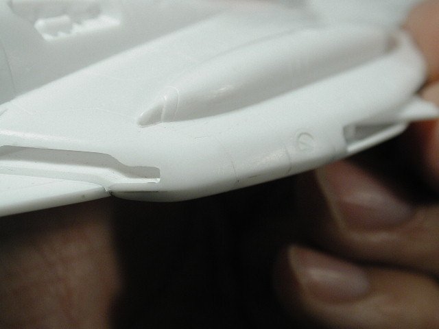
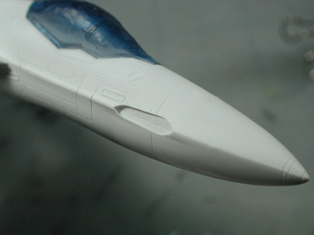
Here's the other side, with any paint and primer sanded off again. The area where the sprue joins the nose cone has kept giving me problems, is just the opposite of a chunk taken away, it's a very minor lump, that can hardly be seen until you paint it. Hopefully its finally gone now. Looks like I need to re-drill some of those bolt holes around the sensor array.

-
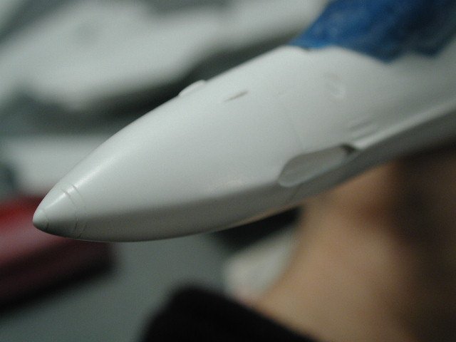
Finally after 3-4 tries, I get a satisfactory profile from round/circular at the tip feathing our to a point near the clear sensor area. I find the nose cone has to be perfect, its the most prominent part of the model.
-
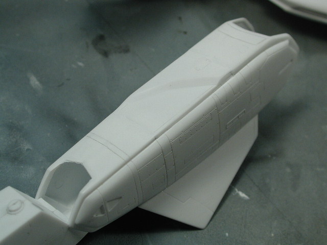
Hey all, I've been sanding, sanding... sanding anytime I get on the bugger. Just when I think I'm done, I prime it in a flat white paint, and some imperfection shows through - so I have to sand it down carefully, using the white paint as a fine filler. After so many tries, I'm pretty much down to the bare plastic. I don't know why I'm having such a hard time this time around - I guess every once in a while you get a model like this - its not that its a bad kit. Just bad luck
-
Woohoo!! hey Rob, please put me down for at least one. Let me know if there is anything I can do to help. What's the status on the mobile launcher - is that included too? I certainly hope so - it provides a much needed base. Question, why are you using the Battroid legs instead of the Fighter legs - I just think the fighter will be more sleek. Hey any chance of a step-by-step progress thread on this?
-
That's what the thick coat of flat white looks like - I will do this in all the problem areas (which is most of all the critical joints ) and attempt to re-sand again... boring, but necessary to achieve a flawless finish. This is often the step I don't spend enough time on - and I always regret it afterwards.

-
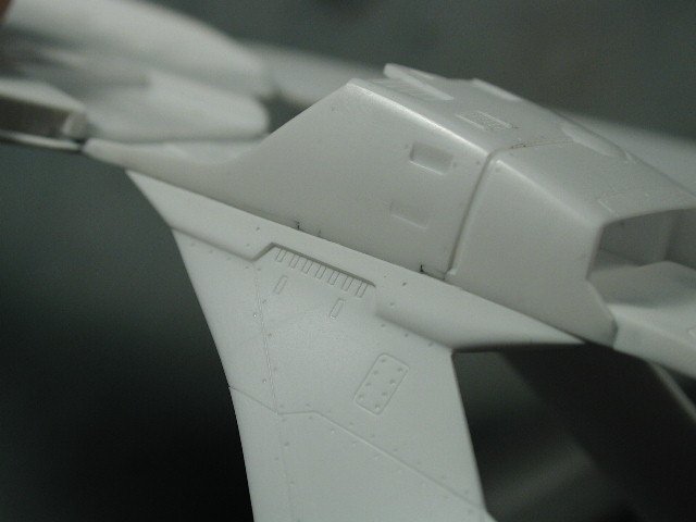
Another critical seam to get right (there seems to be more of them on this model than any other so far). The two little tabs even though they have been sanded smooth, don't seem to mate up with the lower portion of the rudders too well. I will paint a thick coat of flat white across this seam are re-sand.
-
Argh... You can see the slight bump where the sprue originally joined to the forward fuselage halve - damn, I was too impatient and need to sand again to smooth that out. These errors are hard to see before you prime since they are not holes or depressions, they are just the opposite.
-
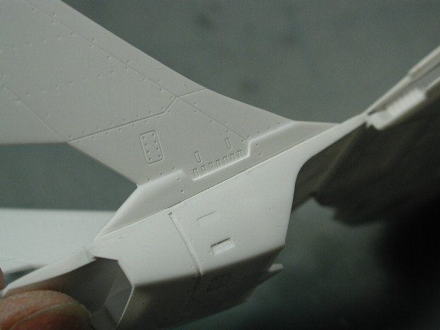
Another spot to inspect carefully. Remember to continue the scribed panel line across the seam to join the underside (I might of scribbed too deeply)
-
Another critical seam that turned out okay. The dark line is the Mr. Surfacer underneath.
-
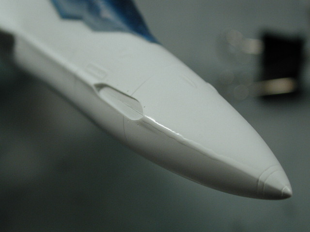
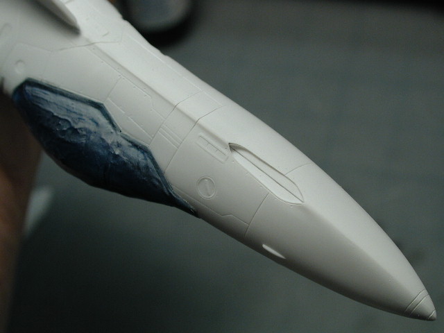
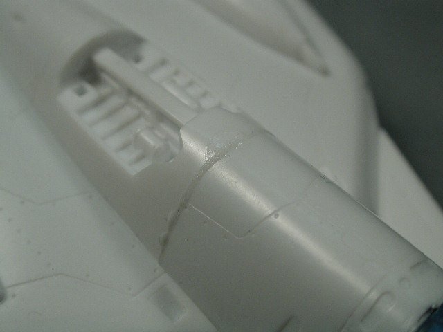
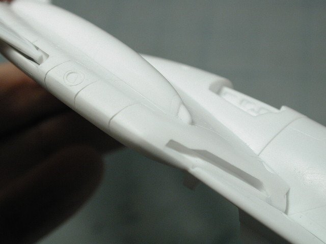
Here's the critical seam that I was absolutely nuts about - while the rear portion after the clear sensor domes worked out, there is a slight blemish in the front radome portion. However, I'm glad that I was able to keep the slightly ridged profile - too much sanding could turn the radome into a cone. I will paint a strip of flat white paint and sand that off to seal in the faint seam (not really visible in this photo) but apparent to the naked eye upon really close inspection.

-
The arms turned out okay - but also major putty here to make the surfaces flat. I also rushed the sanding of this baby - since I was building it in the small bits of free time I had while workng. I think I may have to go back and re-sand quite a few pieces - the seams are still slightly present
-
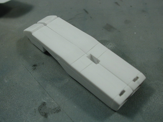
You guys are right those top pieces for the legs fit really poorly common Hasegawa - this isn't up to your usual snuff - what's going on here. It'd even say the gaps around around the order of old AMT/ERTL stuff. Well, I decided to push it to the rear of the leg, leaving the front edge with the big gap - since it would be eventually covered with the grey decal. I lathered on the Mr. Surfacer, then sanded - and here you see a coat of flat white to see where we are. Still not great, but I'll brush on a very thick layer of flat white paint to sand down afterwards to minimize the seam - however, I don't want it smooth, I still want to read a seam here.
-
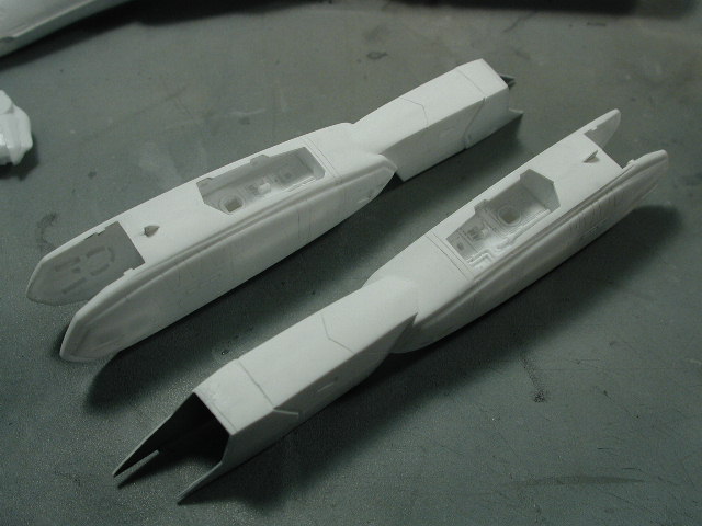
Thanks for the tip about sanding sticks, I just dug some up that I purchased several years ago on a whim and have yet to try them out - I'll use them on those little injection pin depressions in the landing gear wells. Here's a shot of the legs sprayed with some flat white as primer along the filled seams. This helps me see where there still needs to be filled and sanded. Also it helps blend in the grey putty and Mr. Surfacer to the white surrounding parts so that I don't have to use as much paint later on to hide the filled areas.
-
Hey there RM, If you were (or anyone else) doing a resin upgrade kit for the Hasegawa Battroids to the GBP armour - I would definitely be interested. Please post a progress thread - I would follow with great interest. Welcome to the boards! P.S. by the way, great work Fulcy!!