captain america
-
Posts
3550 -
Joined
-
Last visited
Content Type
Profiles
Forums
Events
Gallery
Everything posted by captain america
-
-1/72 Monster: I highly doubt there are enough people willing to shell-out a grand on a kit, and then the hundreds it would cost to ship to various international destinations. Further, I don't think I'd even have the facilities to process something that large. -1/60 Phalanx/Spartan: probably not a bad idea. Both of my 1/72 iterations were excellent, and I could certainly do something cool in 1/60. -1/83 anything: oddball scale, doesn't interest me. Ultimately, it's about numbers.
-

MOSPEADA IKAZUCHI 1/2000 kit by MOSCATO HOBBY?
captain america replied to captain america's topic in Anime or Science Fiction
New proposal here: -
MOSPEADA IKAZUCHI 1/2000 kit by MOSCATO HOBBY?
captain america replied to captain america's topic in Anime or Science Fiction
Killed for lack of interest. -
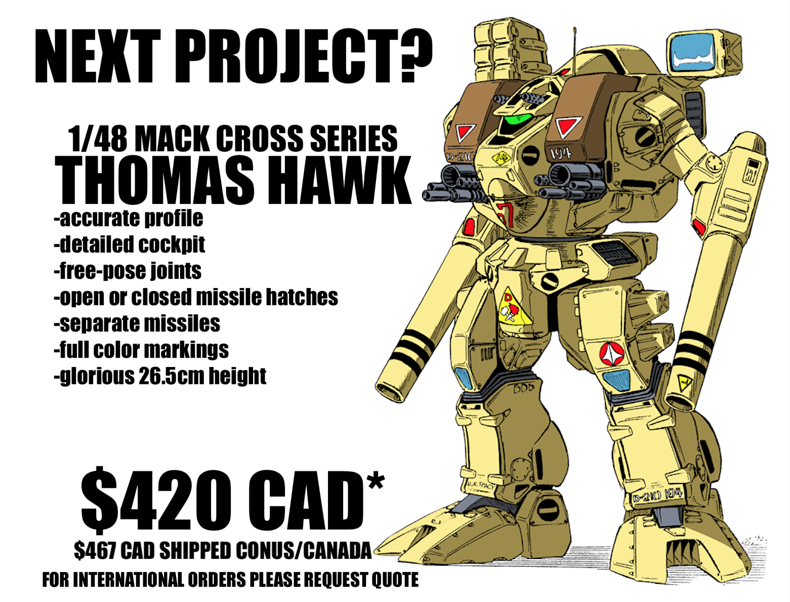
I'd like to propose the next Moscato Hobby Models project: 1/48 DESTOROIIDO THOMAS HAWK ***Conditional upon demand for at least 30 kits received before April 12*** Please send a private message saying “I'M IN” if you want this kit; just posting in the thread will not will not be construed as intent to purchase. Features: -accurate profile -detailed cockpit -free-pose joints -open or closed missile hatches -separate missiles -full color markings Price is listed in the image. Shipping to Hawaii and international destinations will be quoted upon request.
-
MOSPEADA IKAZUCHI 1/2000 kit by MOSCATO HOBBY?
captain america replied to captain america's topic in Anime or Science Fiction
Remember guys, only a private message for the kit counts as genuine interest. -
MOSPEADA IKAZUCHI 1/2000 kit by MOSCATO HOBBY?
captain america replied to captain america's topic in Anime or Science Fiction
Total rethink and re-sizing. -
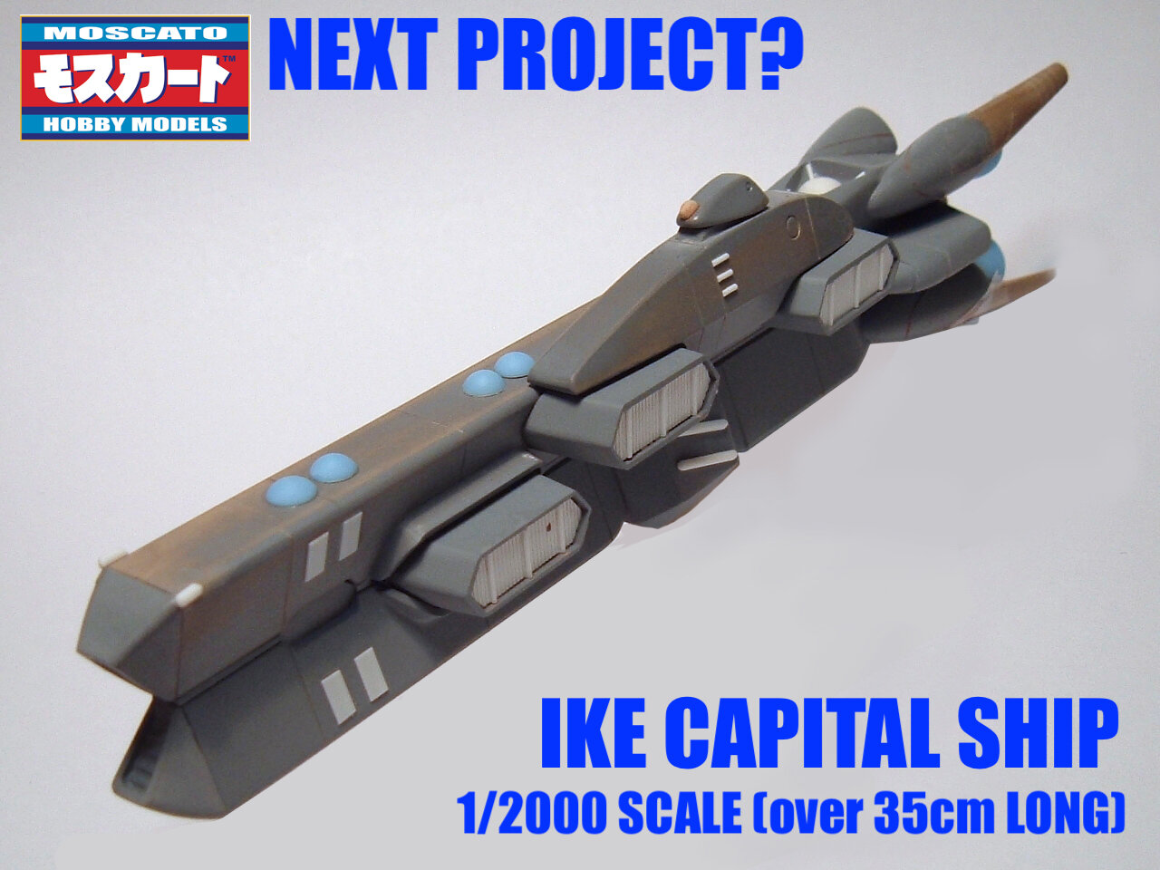
I'd like to propose the next Moscato Hobby Models resin kit: a 1/2000 Ikazuchi (hereafter Ike Capital Ship.) The kit would come in at a little over 35cm in length. Kit features: -positionable open or closed soldier launch bays (no removable soldiers!) -included decal markings for 3 different ships -positionable gun turrets -translucent resin thrusters for easier lighting Proposed kit price before shipping: $325 Canadian dollars Kit price with shipping to Canada/US contiguous: $374 Canadian dollars International shipping: see below I need a minimum of 30 orders to proceed with the project, so I’ll leave this up until April 7th. To voice your acceptance of the project, send me a private message telling me: -« I’m in! » -how many kits you’d like -if you’re not in the US or Canada, your shipping location, so I can calculate the shipping to you. Posting in the thread/asing questions is cool, but will not be construed as intent to purchase. If I don’t get sufficient interest by then, I’ll simply move to another project. Aaaand we’re off!
-
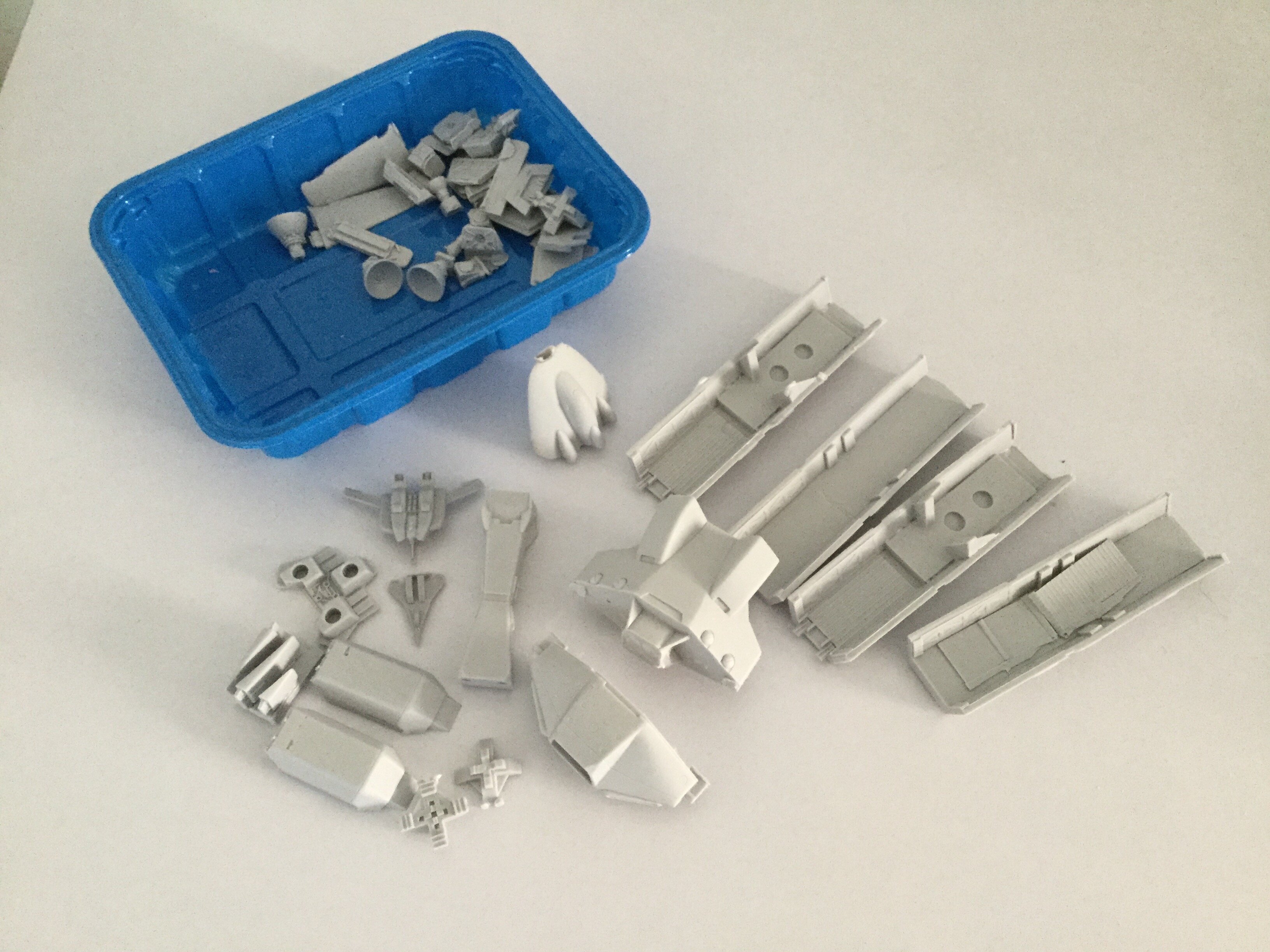
MOSPEADA HORIZONT in 1/350?
captain america replied to captain america's topic in Anime or Science Fiction
Molds are thoroughly baked and done; castings are underway. ☺️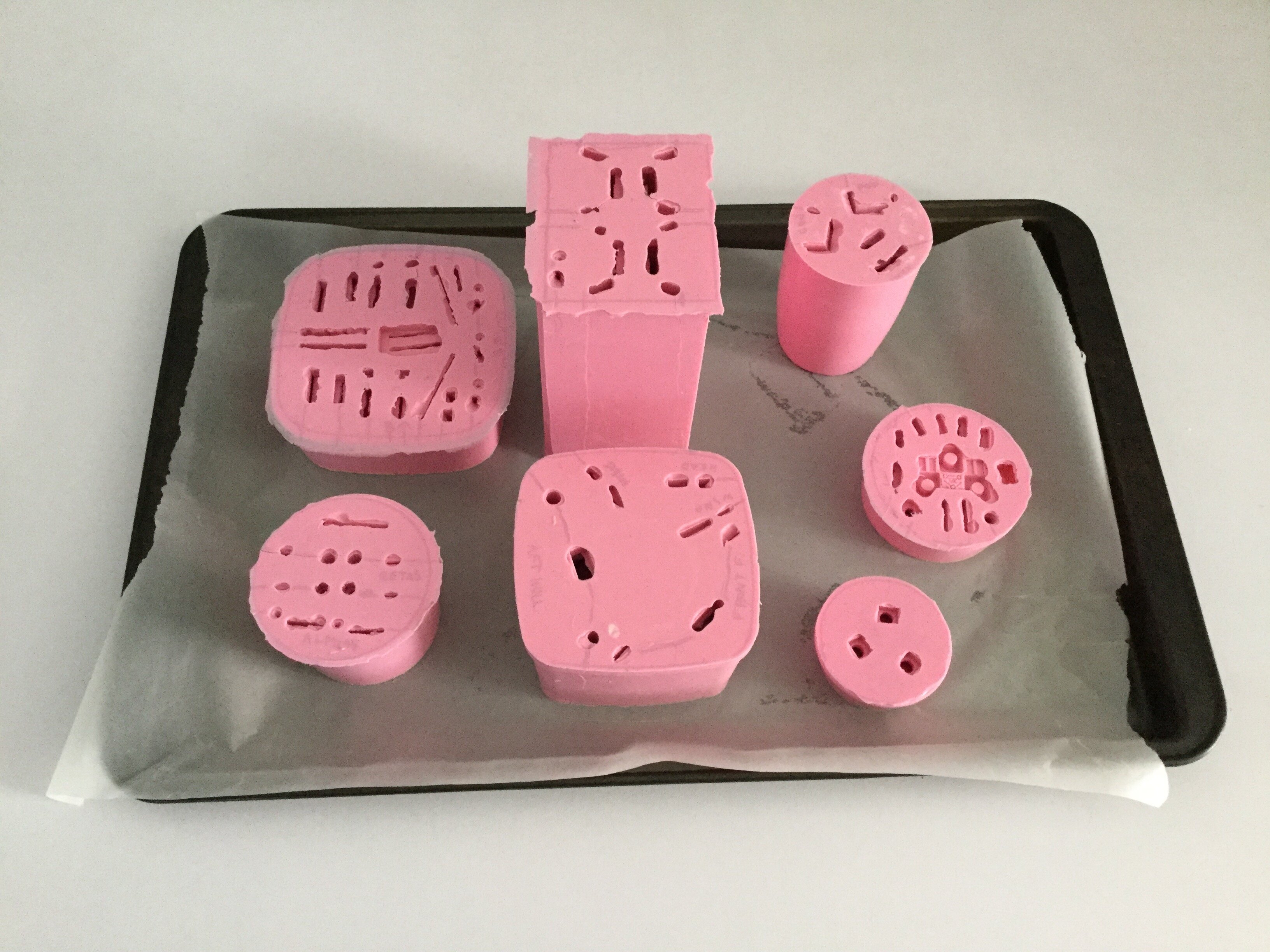
-
1/6 MOSPEADA Rider Project Proposal
captain america replied to captain america's topic in Anime or Science Fiction
Thats a very interesting body suit, it looks unusually shiny. Might you have a link to where you got it from? By the way, your progress on the figure is looking excellent! -
MOSPEADA HORIZONT in 1/350?
captain america replied to captain america's topic in Anime or Science Fiction
Looks like we have the 10 orders for the 1/350 Horizontal ship, so you can send in your payments starting now. I will wait until March 3rd at the latest to collect the payments for those 10 minimum orders. If by that time they haven't all been received, I will simply refund everyone who did pay and move on to another project. -
1/6 MOSPEADA Rider Project Proposal
captain america replied to captain america's topic in Anime or Science Fiction
I don't think enough people would be willing to pay >$800 CAD for the bike, even if it could be built in either mode. A non-variable motorcycle wouldn't be far off from that price either: at that scale, the component breakdown needed to get the detail would be so similar to a dual-mode kit that you might as well do it right. I have slightly more hope for the female rider, if only because a few parts world cross-over and the price would be less prohibitive. Either way, a project has to be financially viable. -
1/6 MOSPEADA Rider Project Proposal
captain america replied to captain america's topic in Anime or Science Fiction
I don't understand your qustion: what's a box that bolts onto the back, and how does that differ from every other project I undertake? Sentinel made a fully variable MOSPEADA unit, so from a geometry perpective, it's feasible. That said, the armor and the boots on the figure already tax the figure's joints to the max, so any backpack would only function with a stand to support the weight. Second, anything of that nature would be significantly more complicated to make than the armor suit, and would be even more work than the 1/32 Legioss, so extremely costly. Considering how many people initially expressed interest in the 1/6 rider then flaked-out, the odds I'll try to crowdfund that project are zero. The only hope would be for someone to bankroll it. -
1/6 MOSPEADA Rider Project Proposal
captain america replied to captain america's topic in Anime or Science Fiction
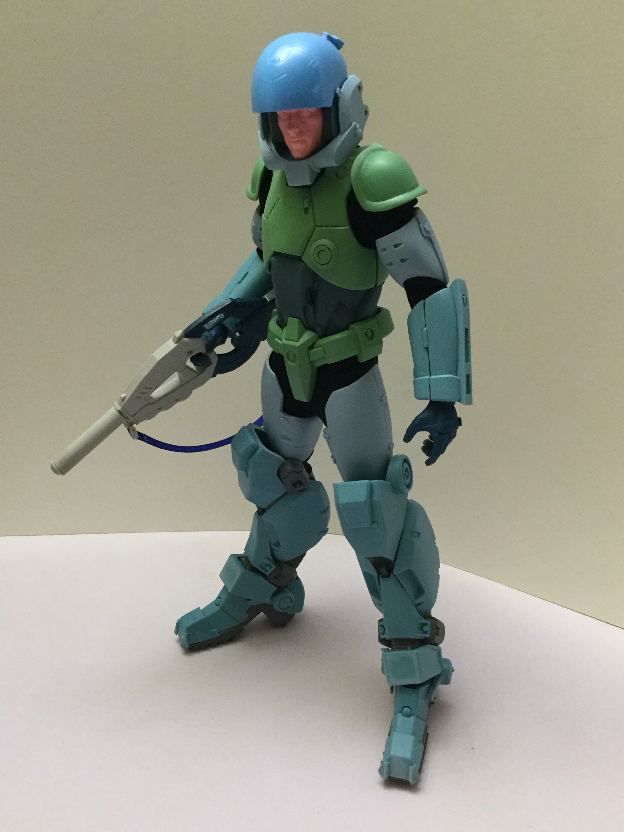
That's a modified casting of the head of the guy who plays Spider-Man in the newest Marvel movies, his name escapes me; It's a digital scan of his face. Your "basic skin texturing" looks excellent, by the way! -
MOSPEADA HORIZONT in 1/350?
captain america replied to captain america's topic in Anime or Science Fiction
Hey y'all. Looking to see if there's interest in a re-issue. 10 orders minimum to make it happen.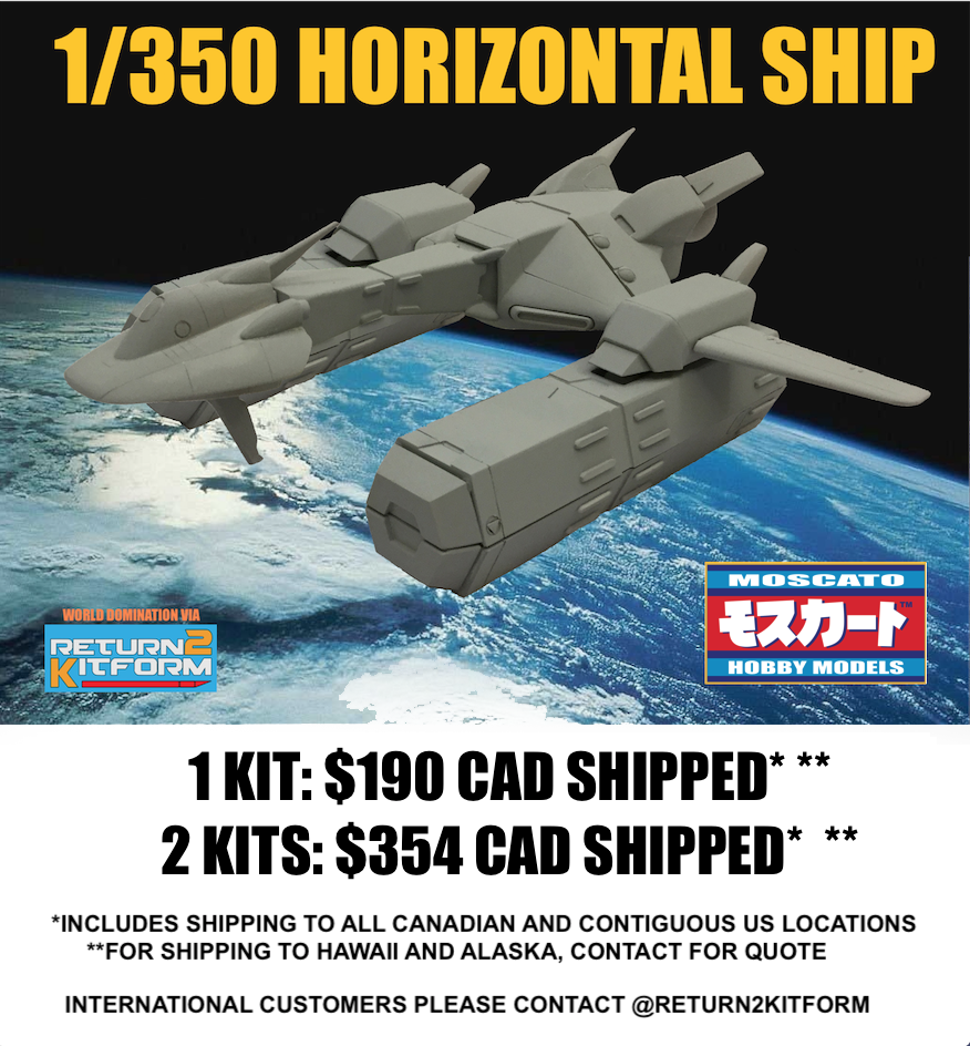
-
No Love for Southern Cross?
captain america replied to blacklotus's topic in Anime or Science Fiction
- 1465 replies
-
- 1
-

-
- Southern Cross
- anime
- (and 8 more)
-
1/6 MOSPEADA Rider Project Proposal
captain america replied to captain america's topic in Anime or Science Fiction
Genesis Climber Mospeppa! 😆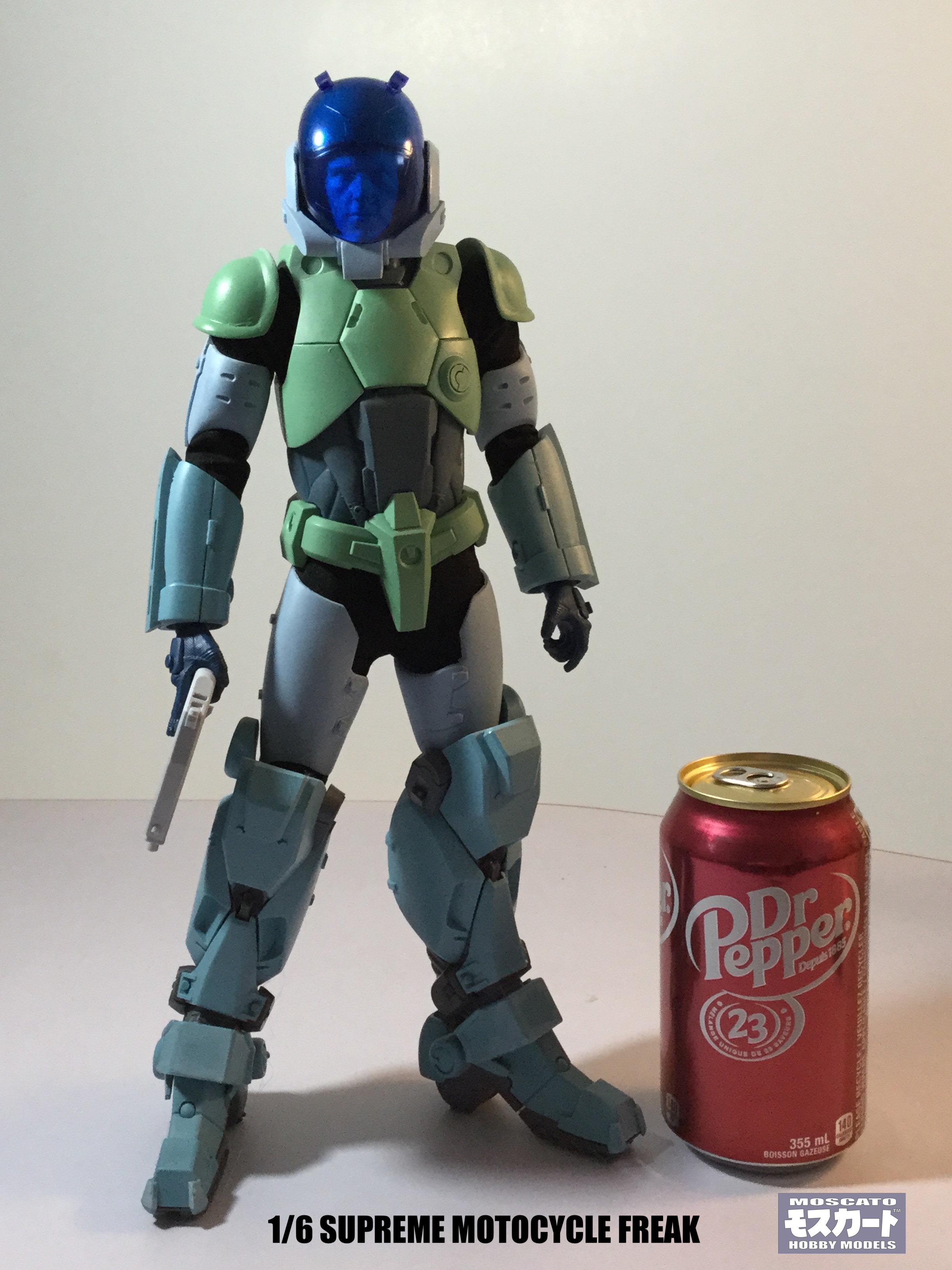
-
1/6 MOSPEADA Rider Project Proposal
captain america replied to captain america's topic in Anime or Science Fiction
And the rest.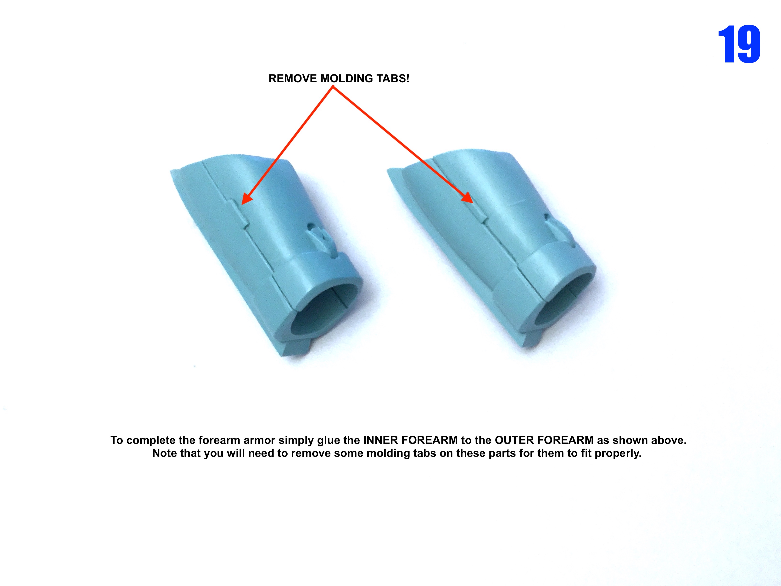
-
1/6 MOSPEADA Rider Project Proposal
captain america replied to captain america's topic in Anime or Science Fiction
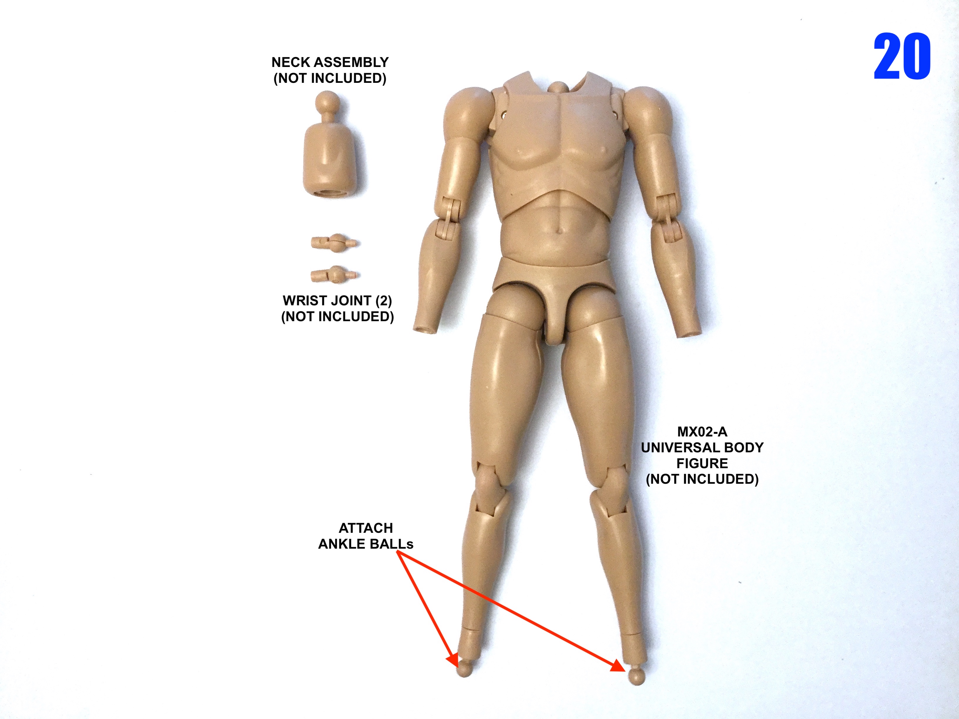
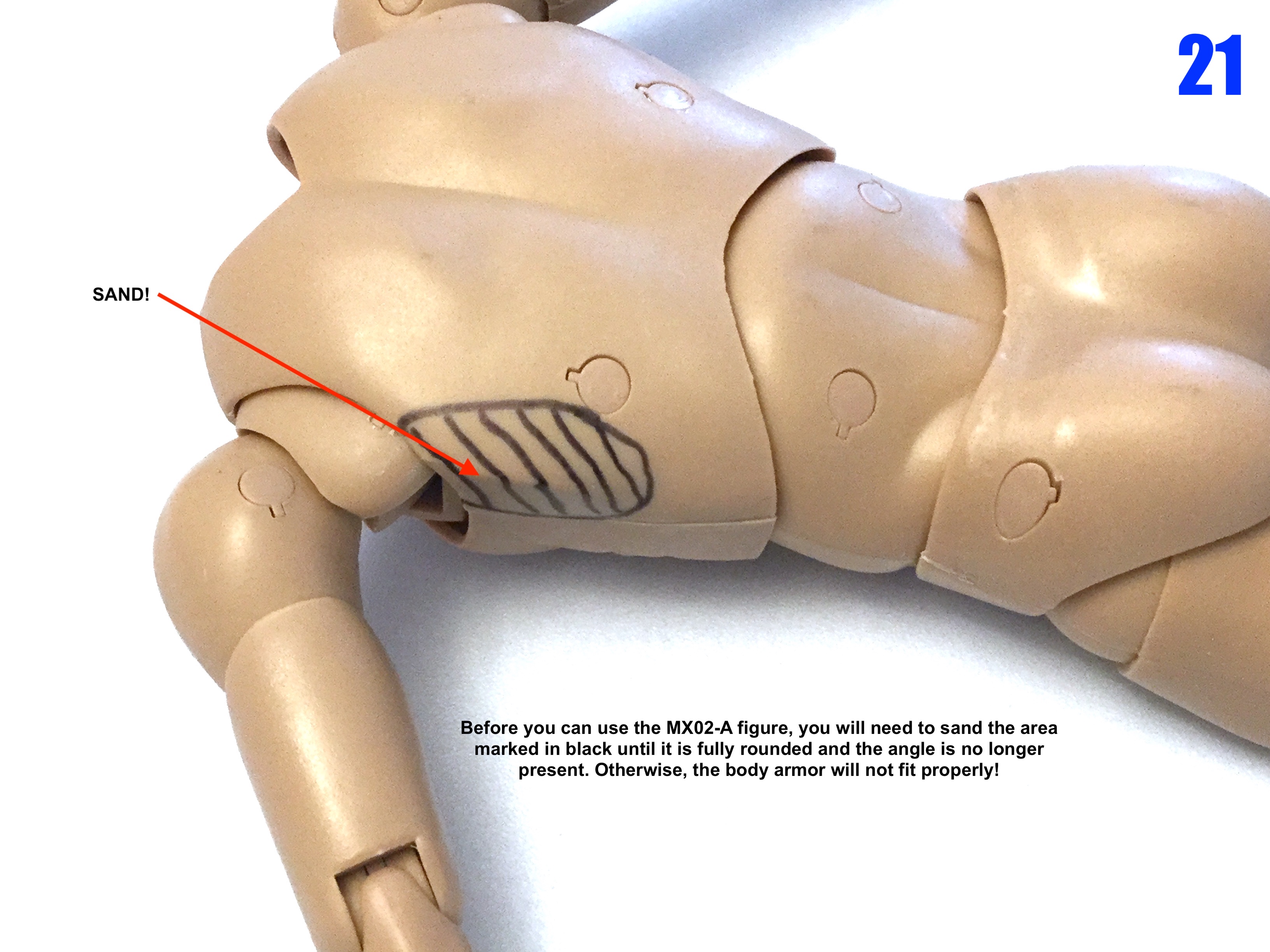
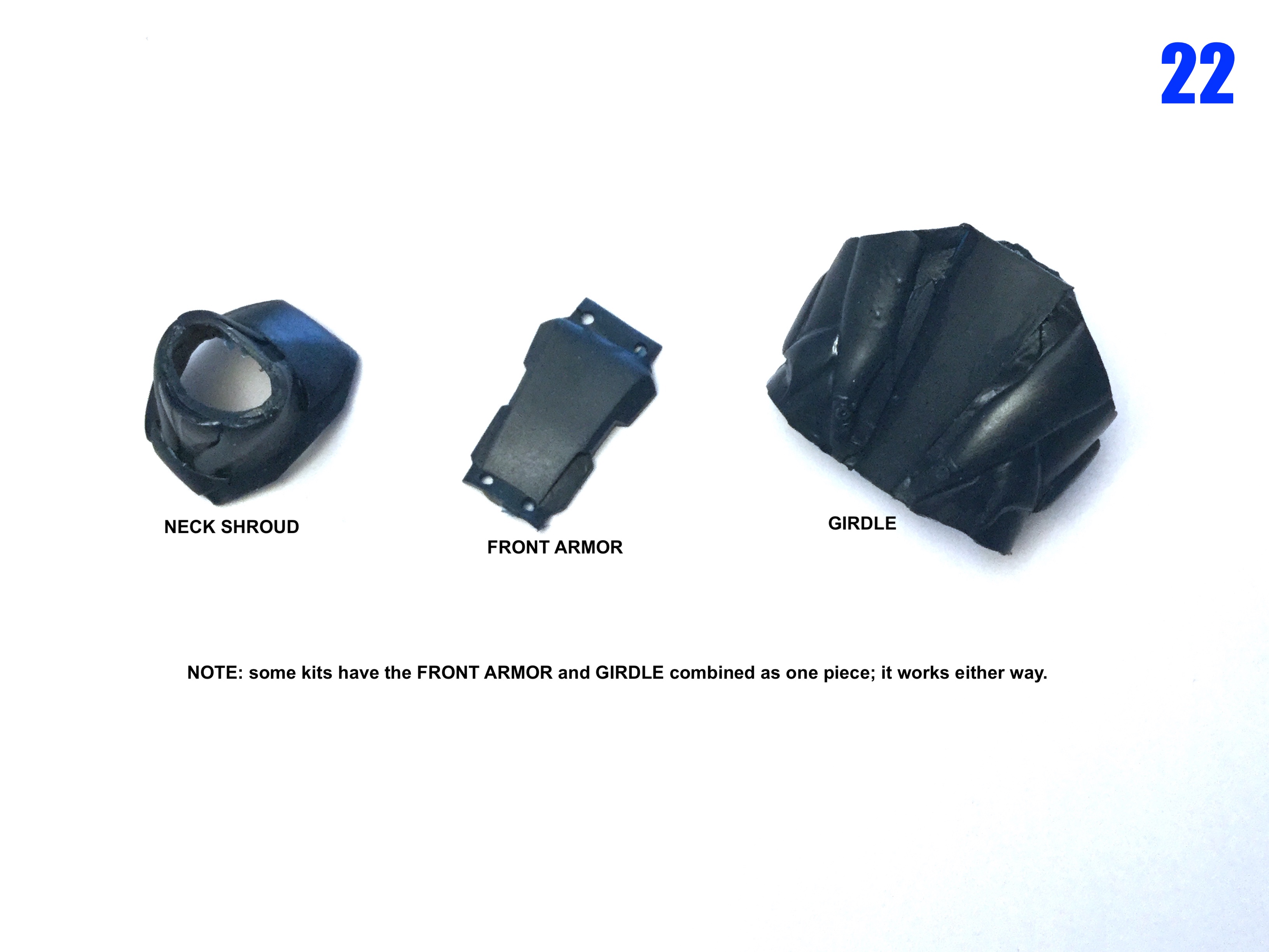
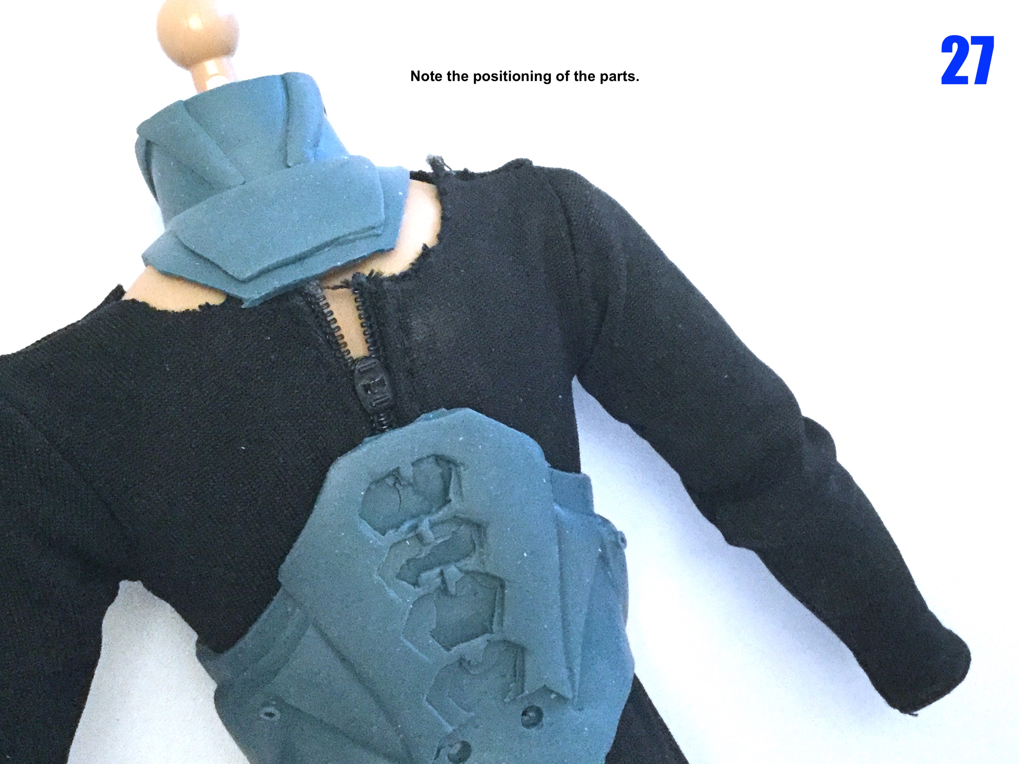
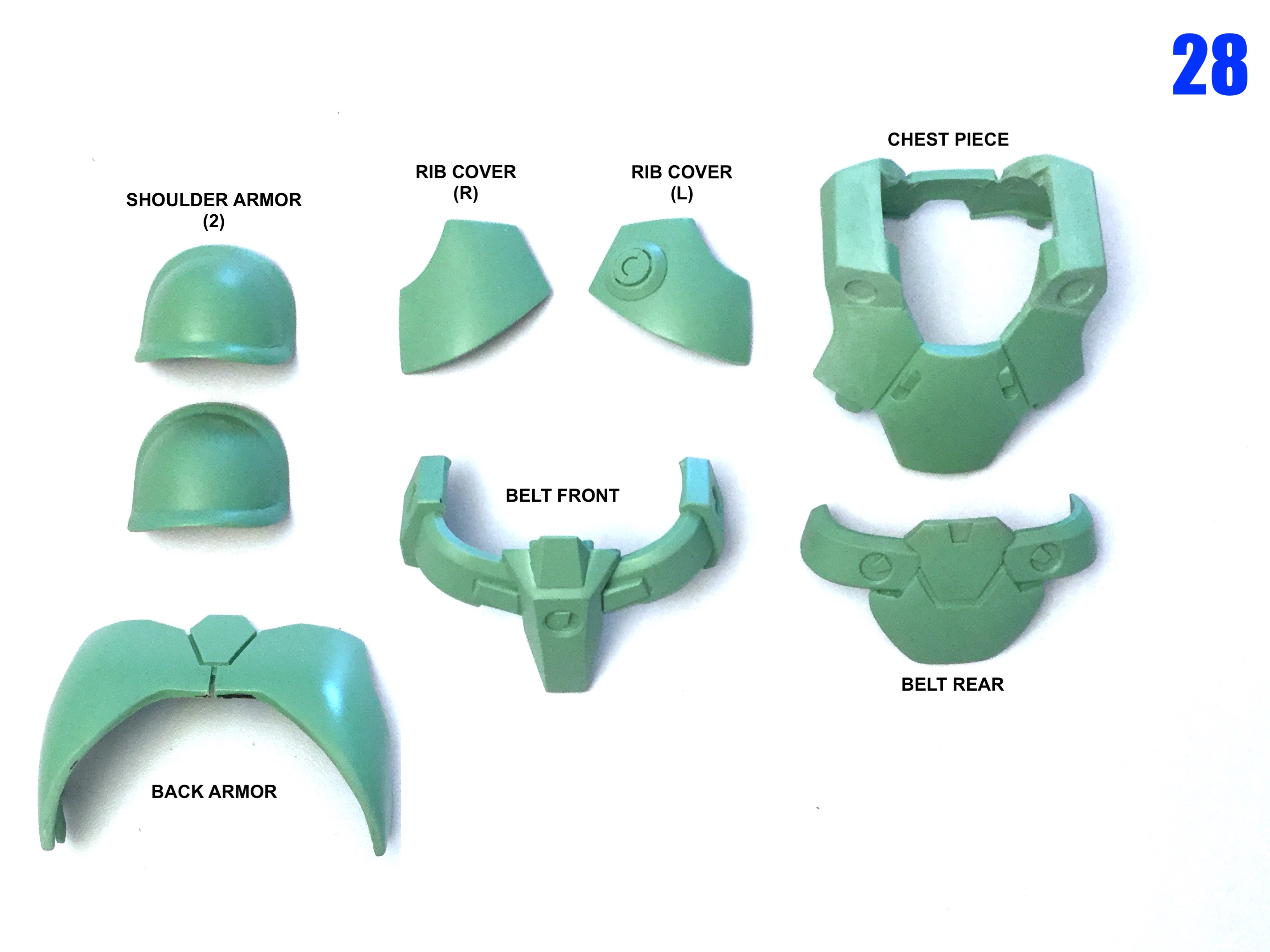
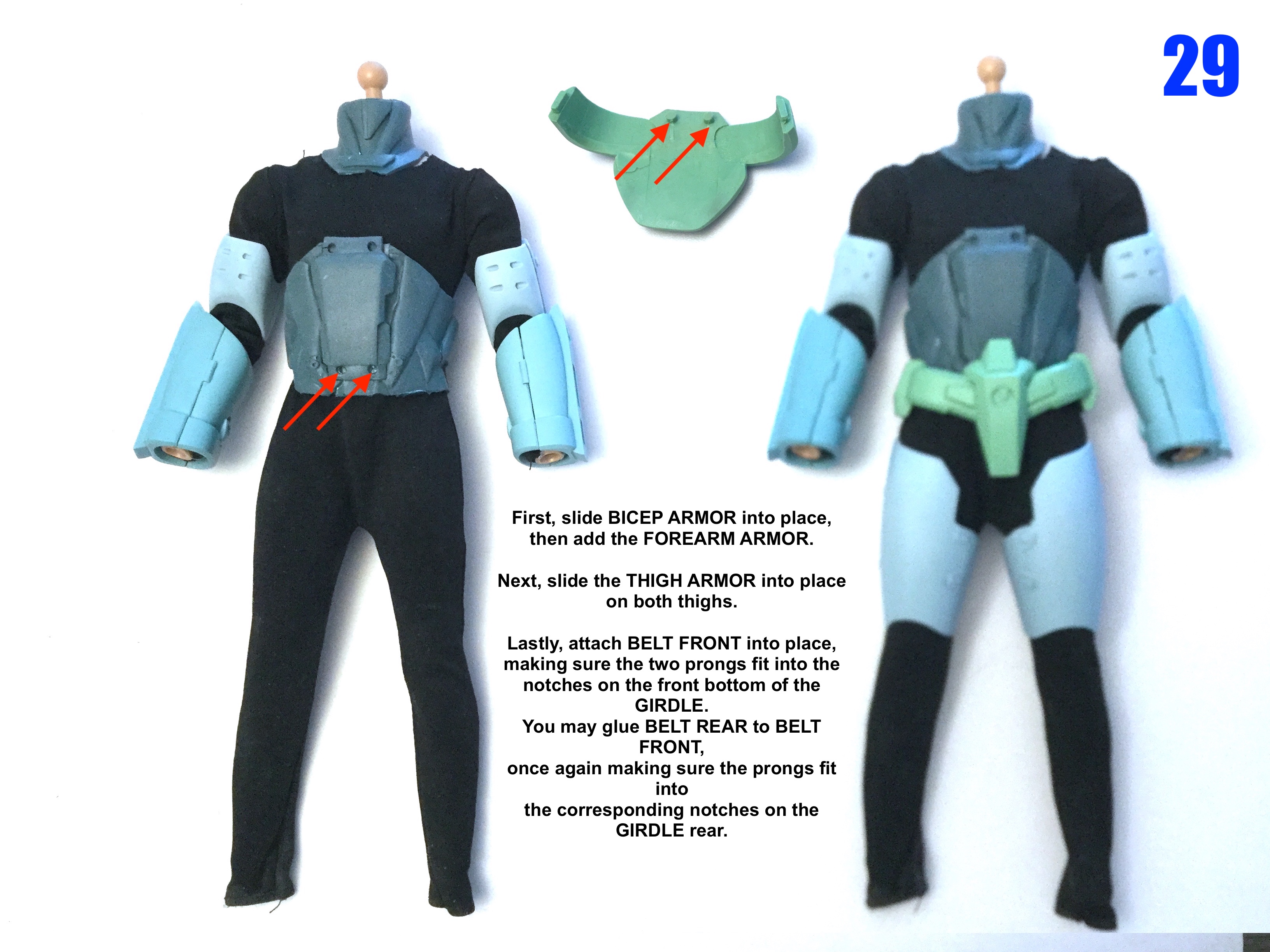
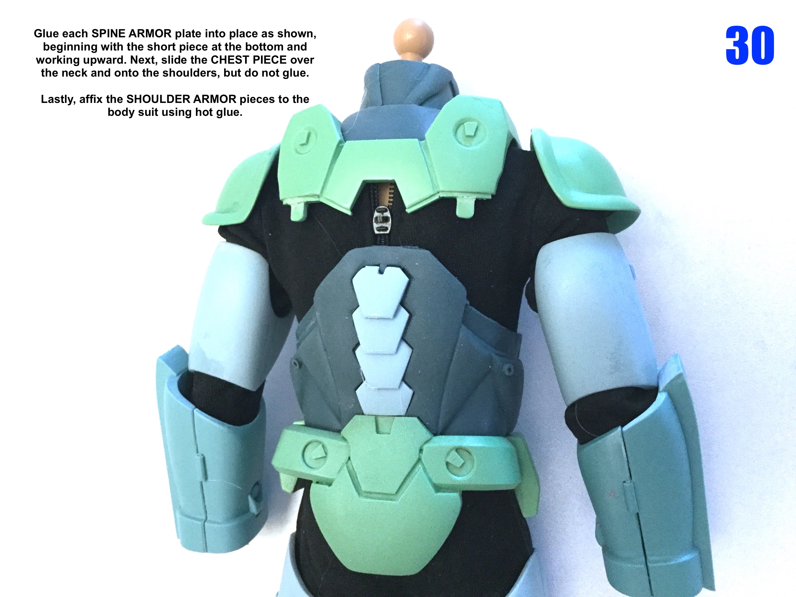
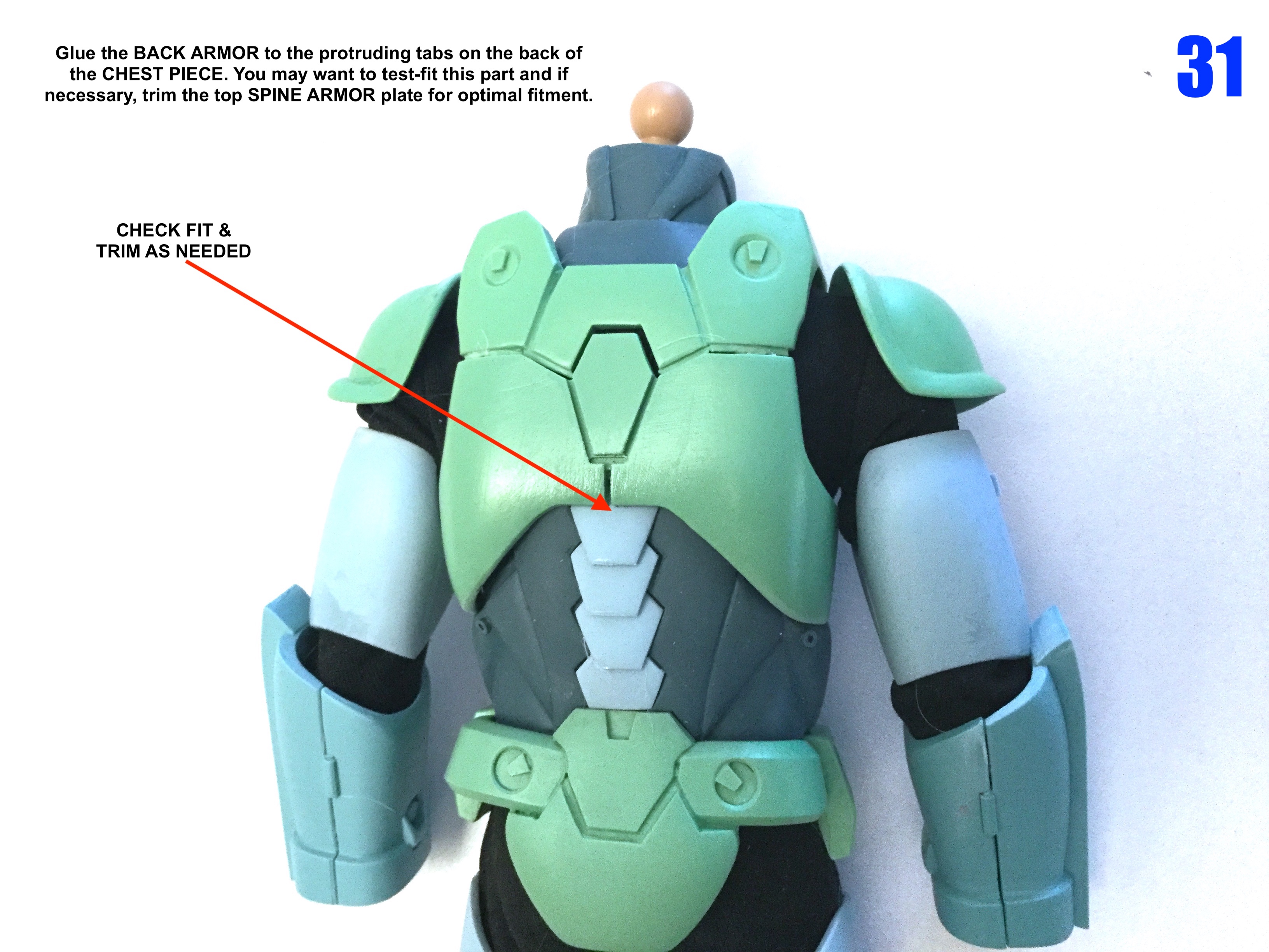
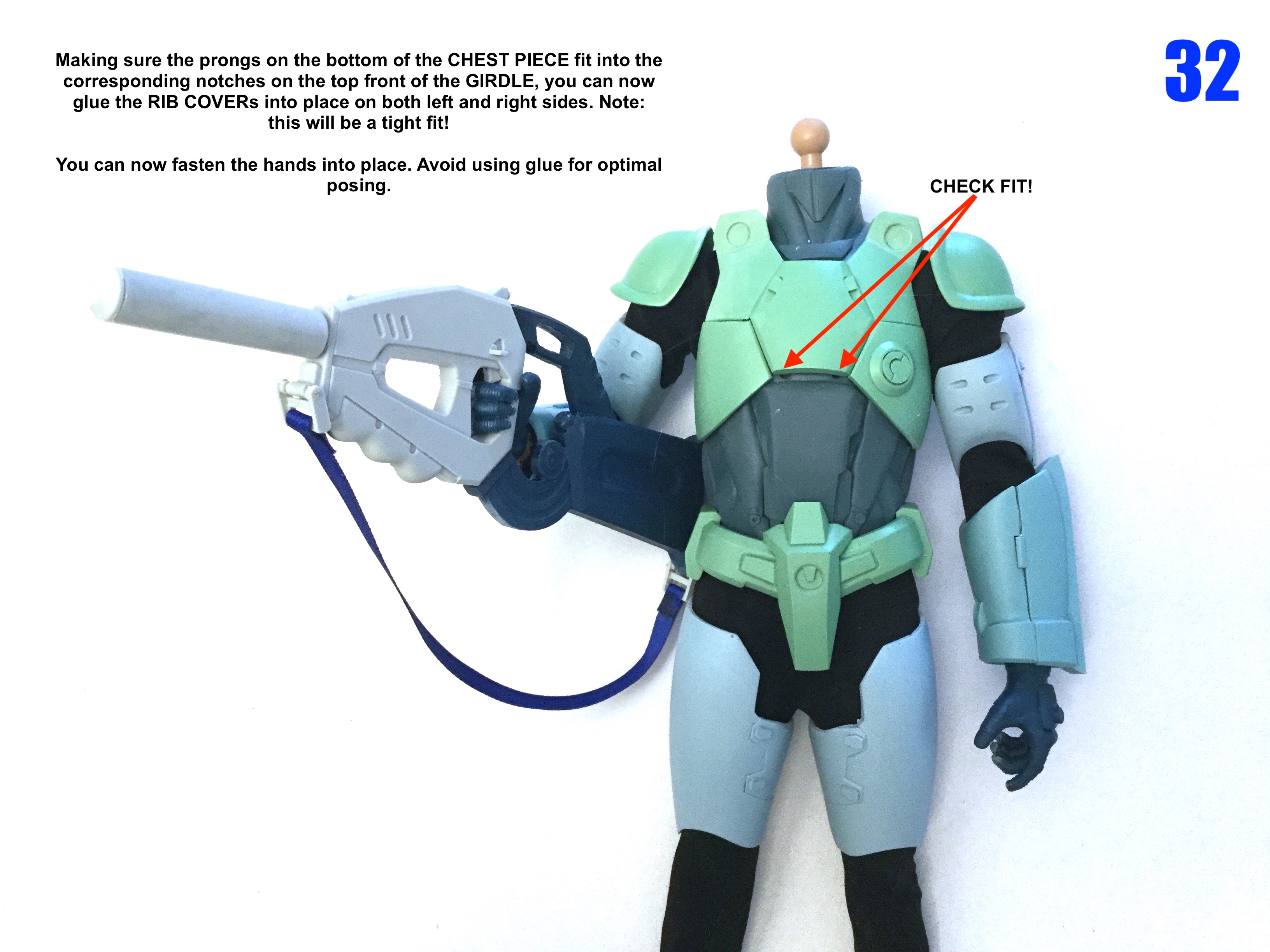
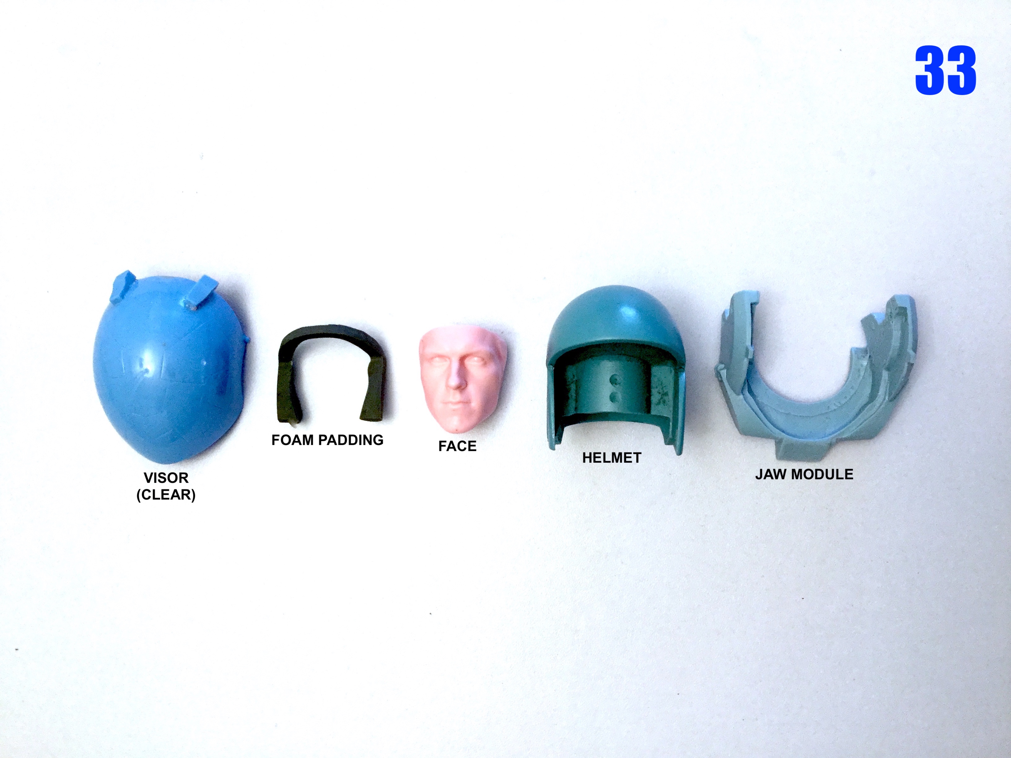
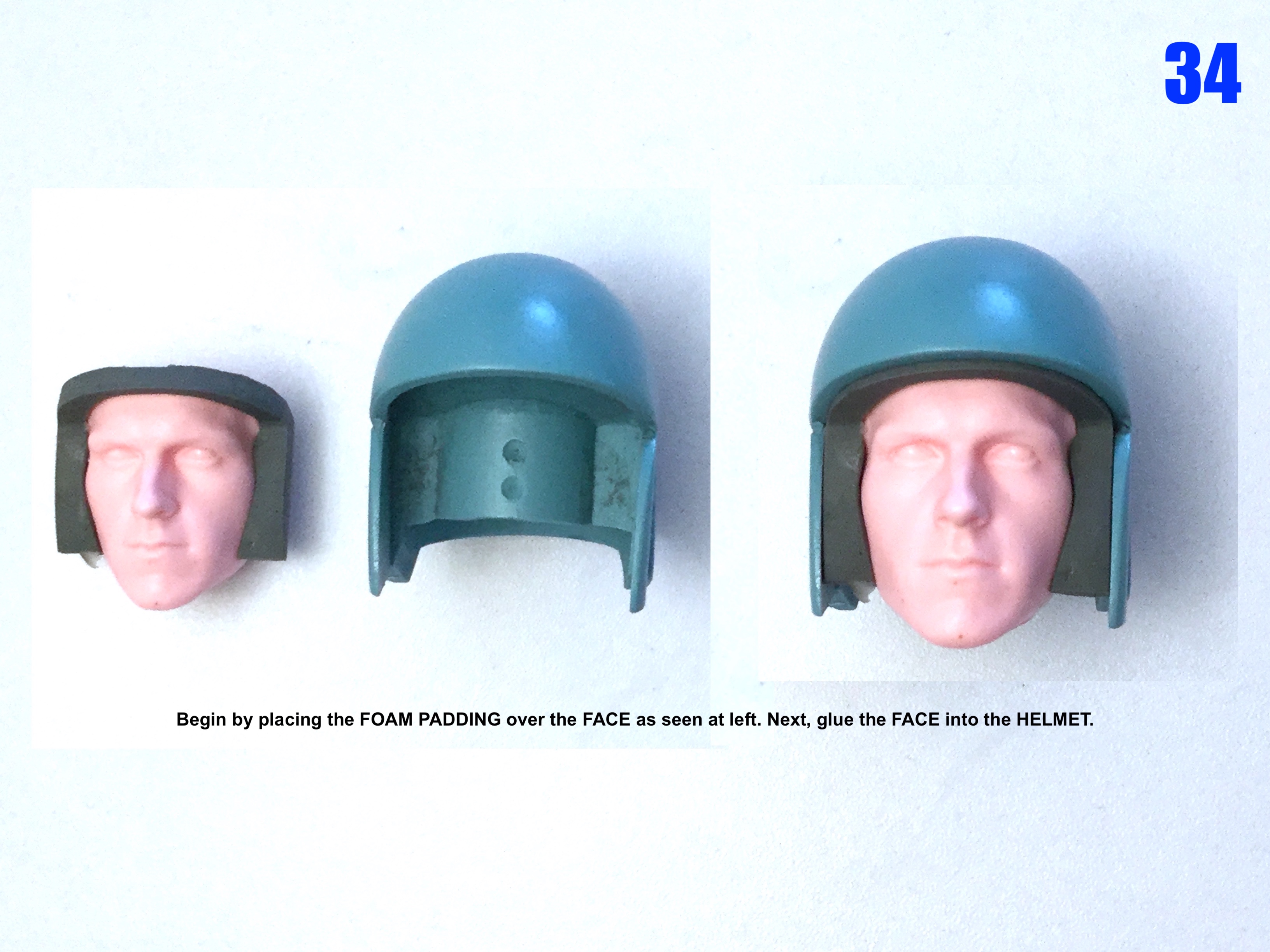
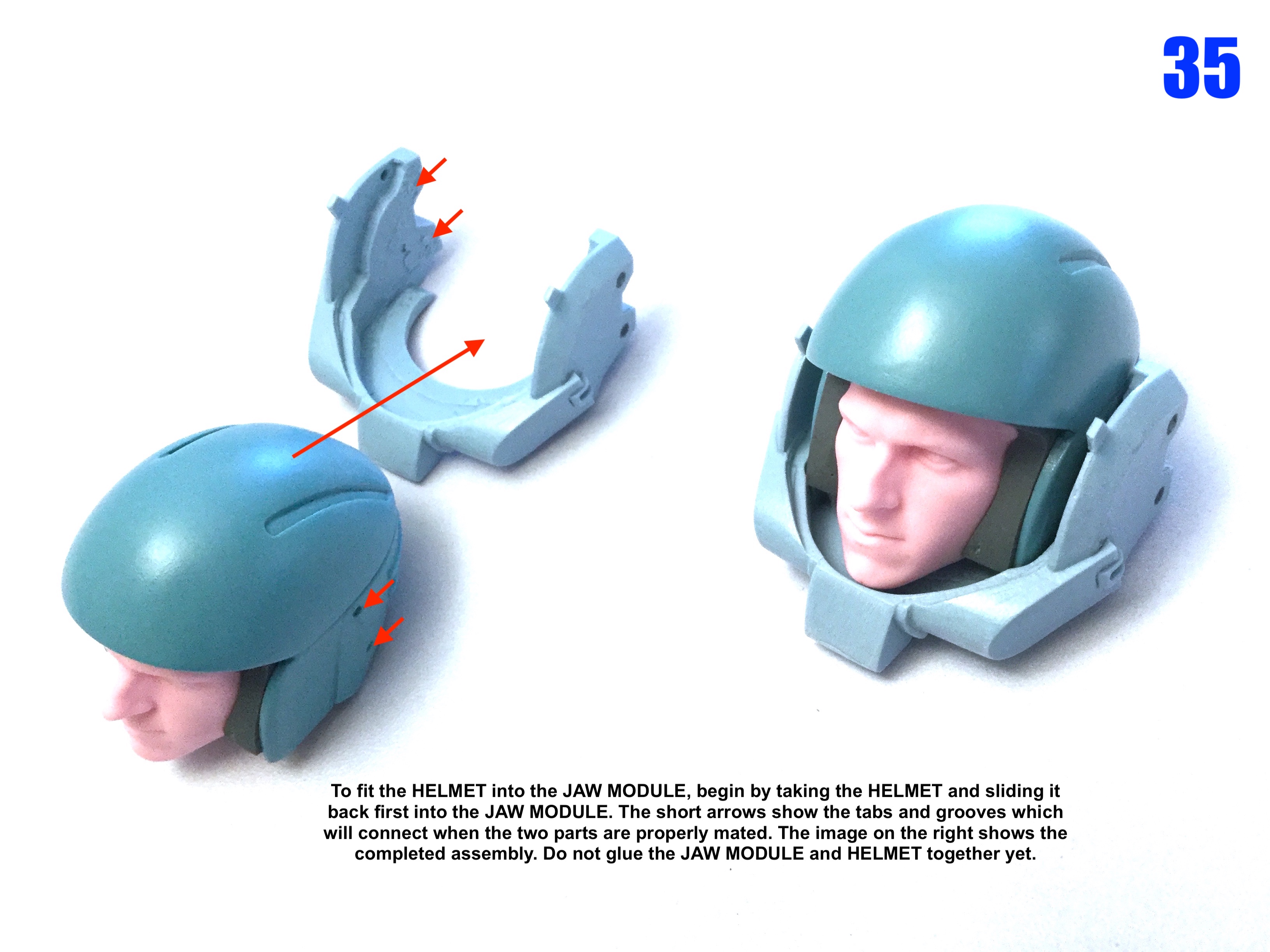
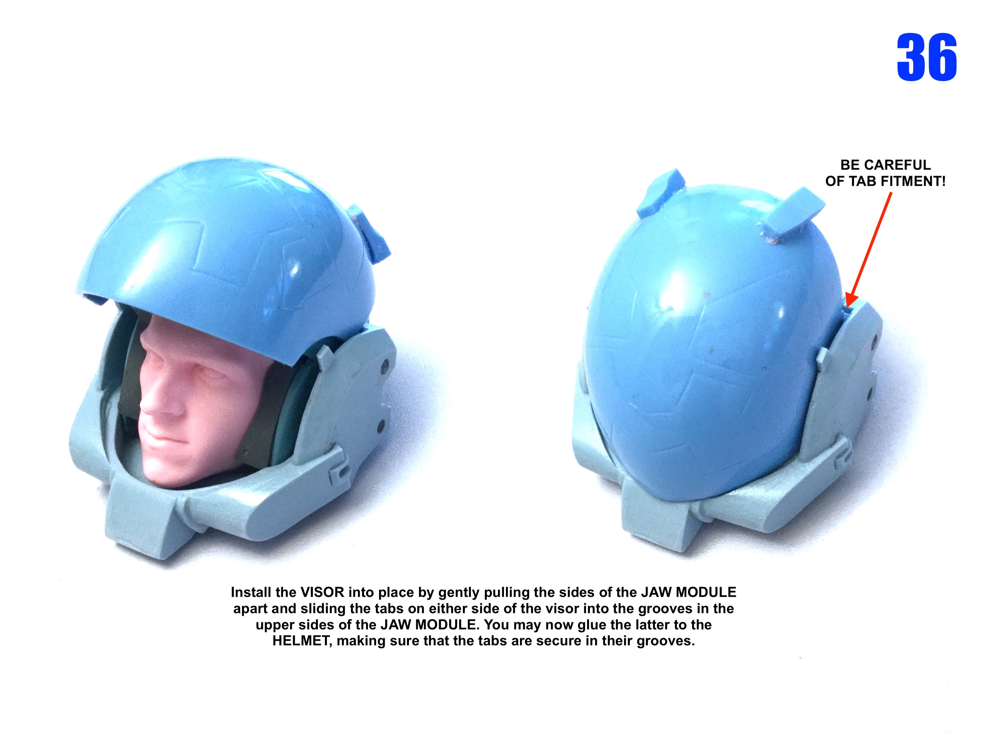
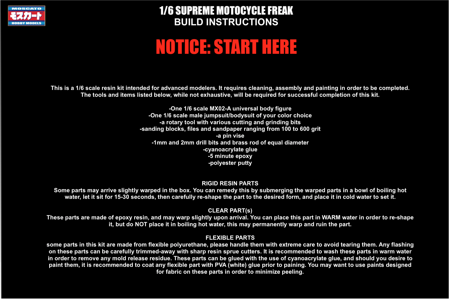
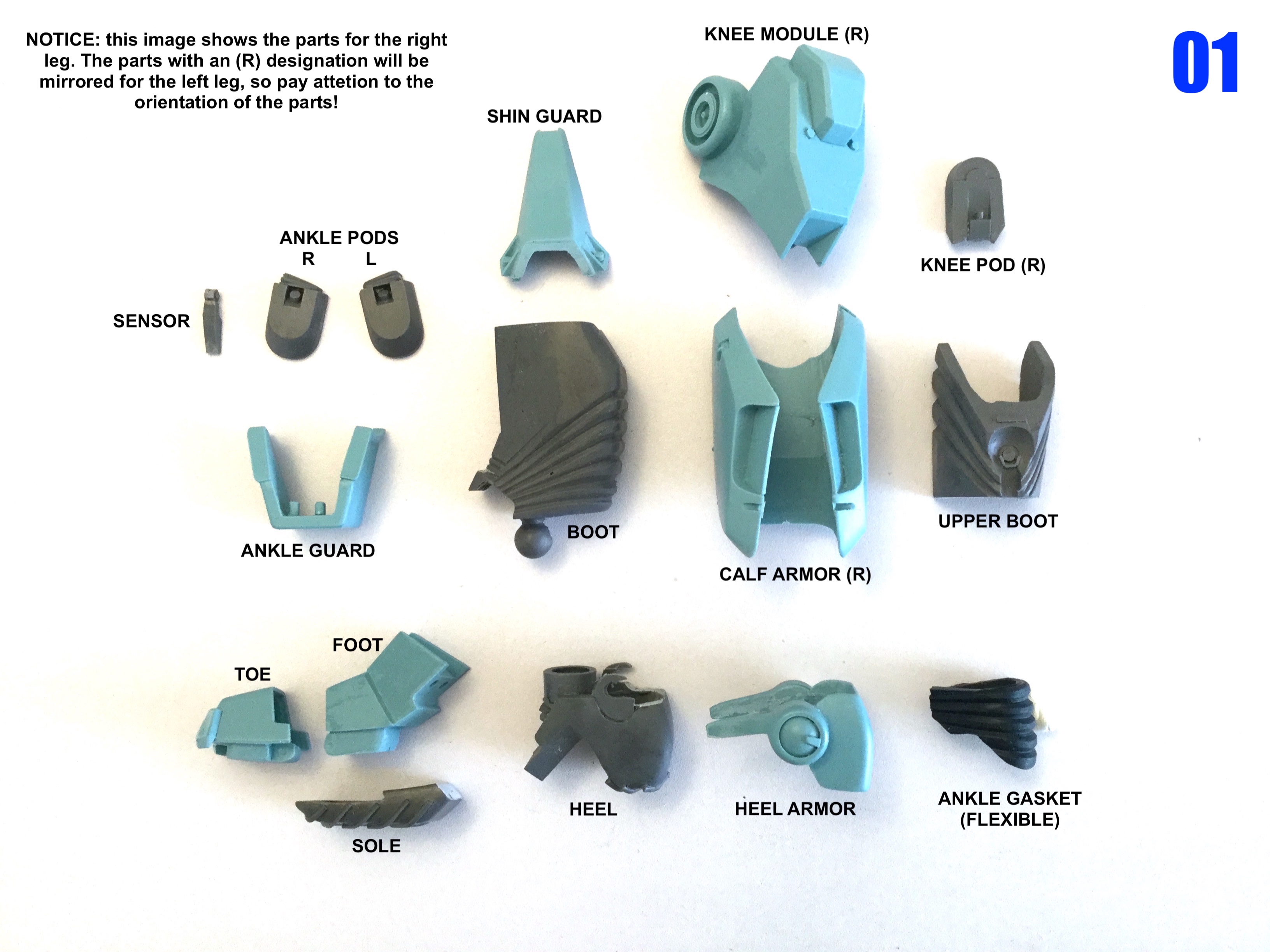
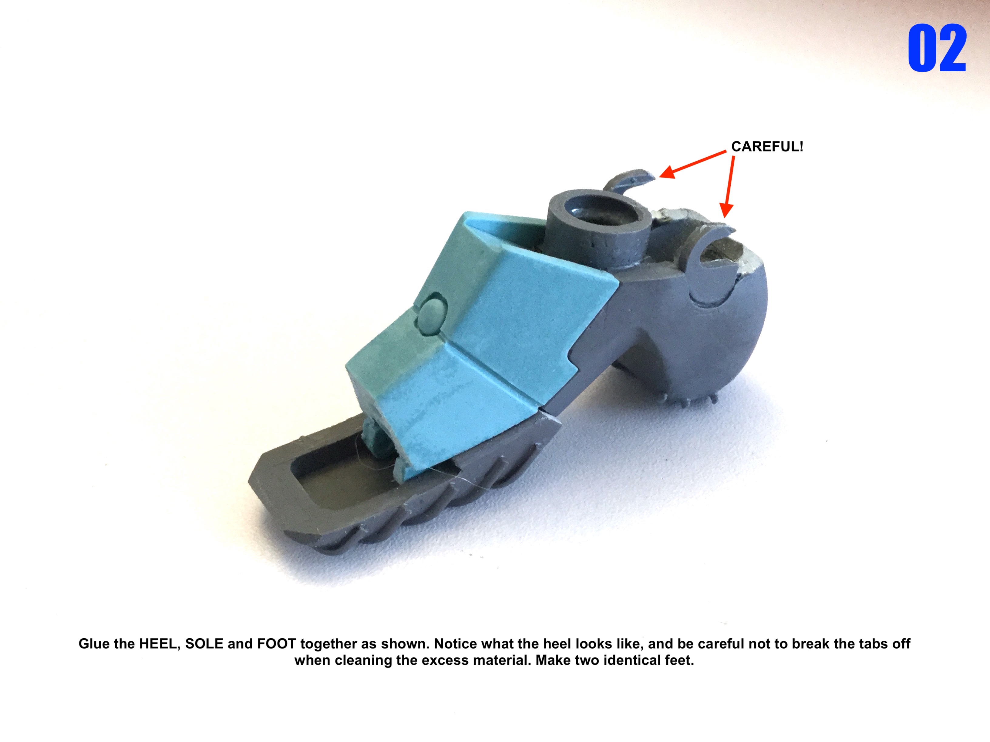
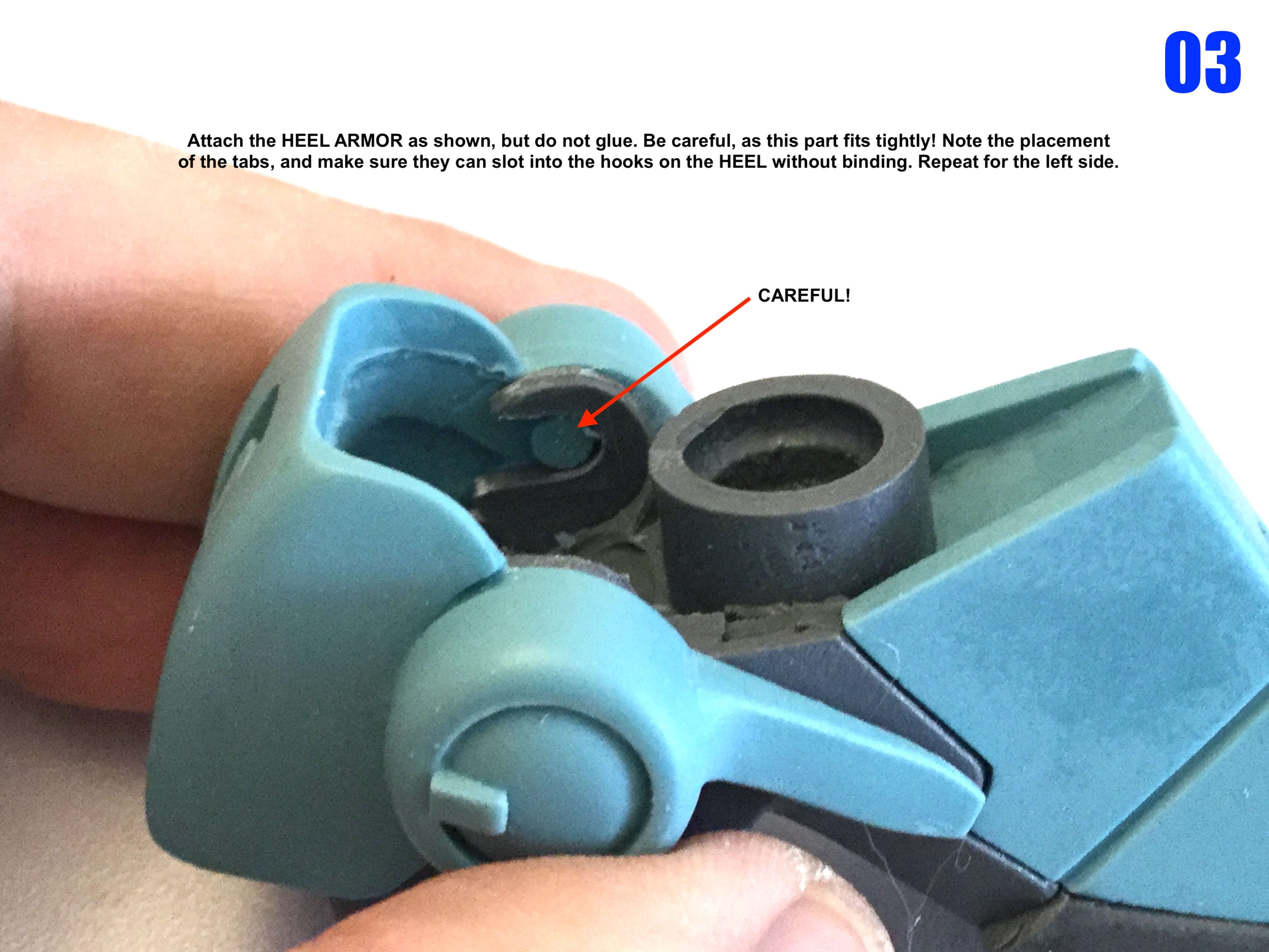
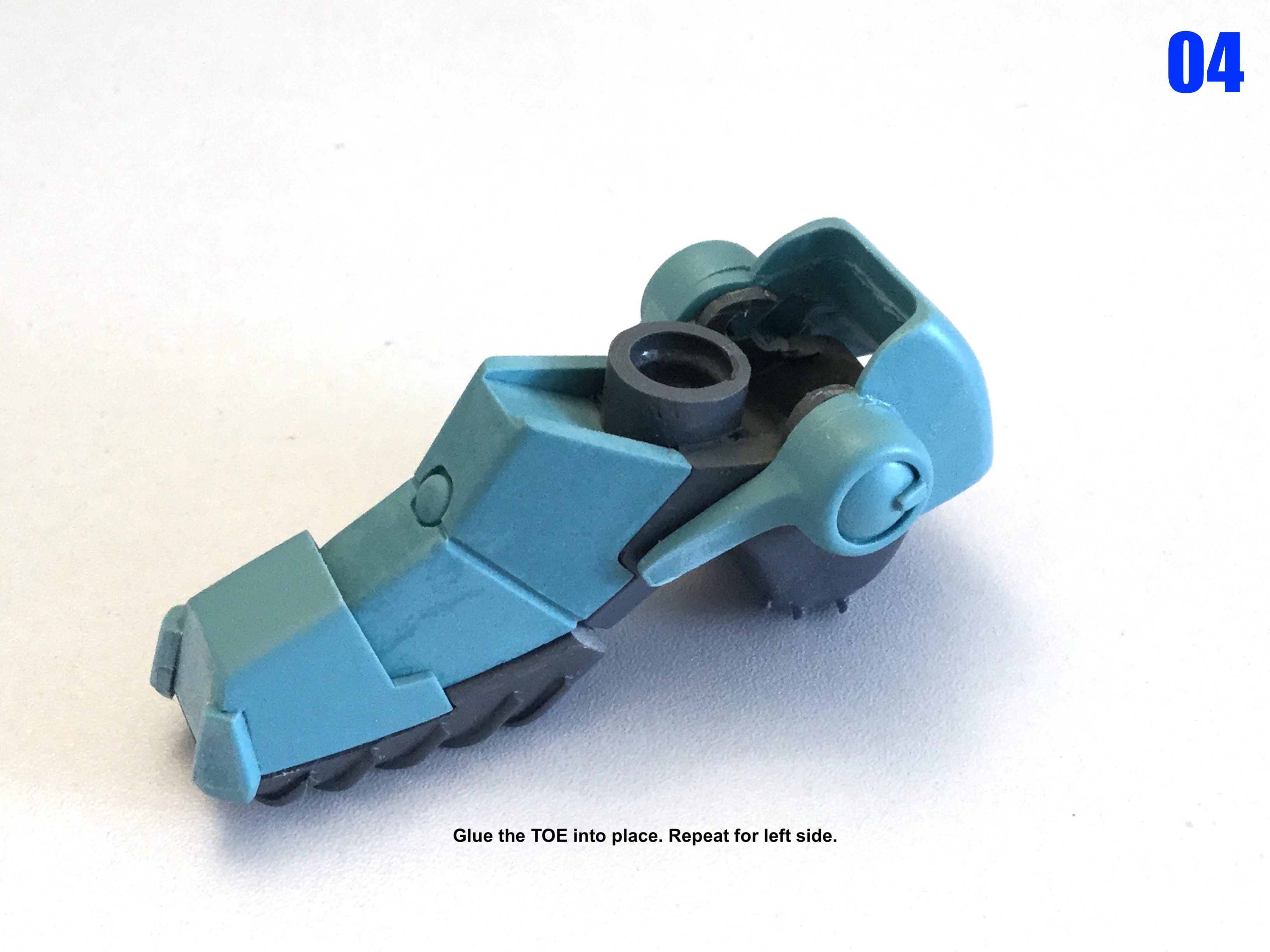
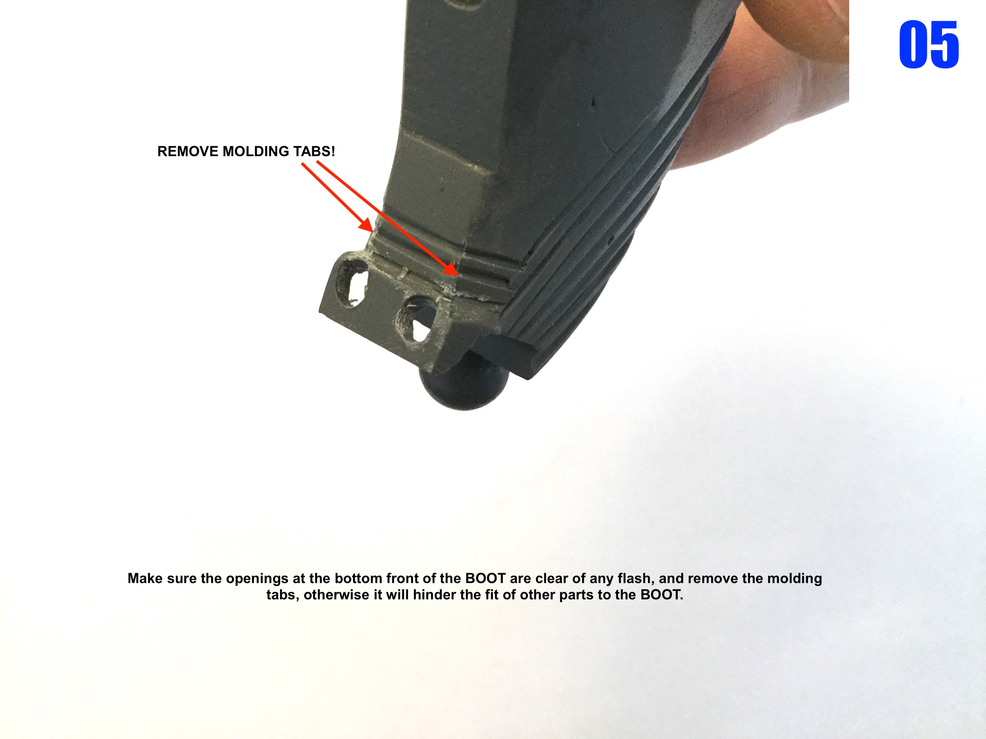
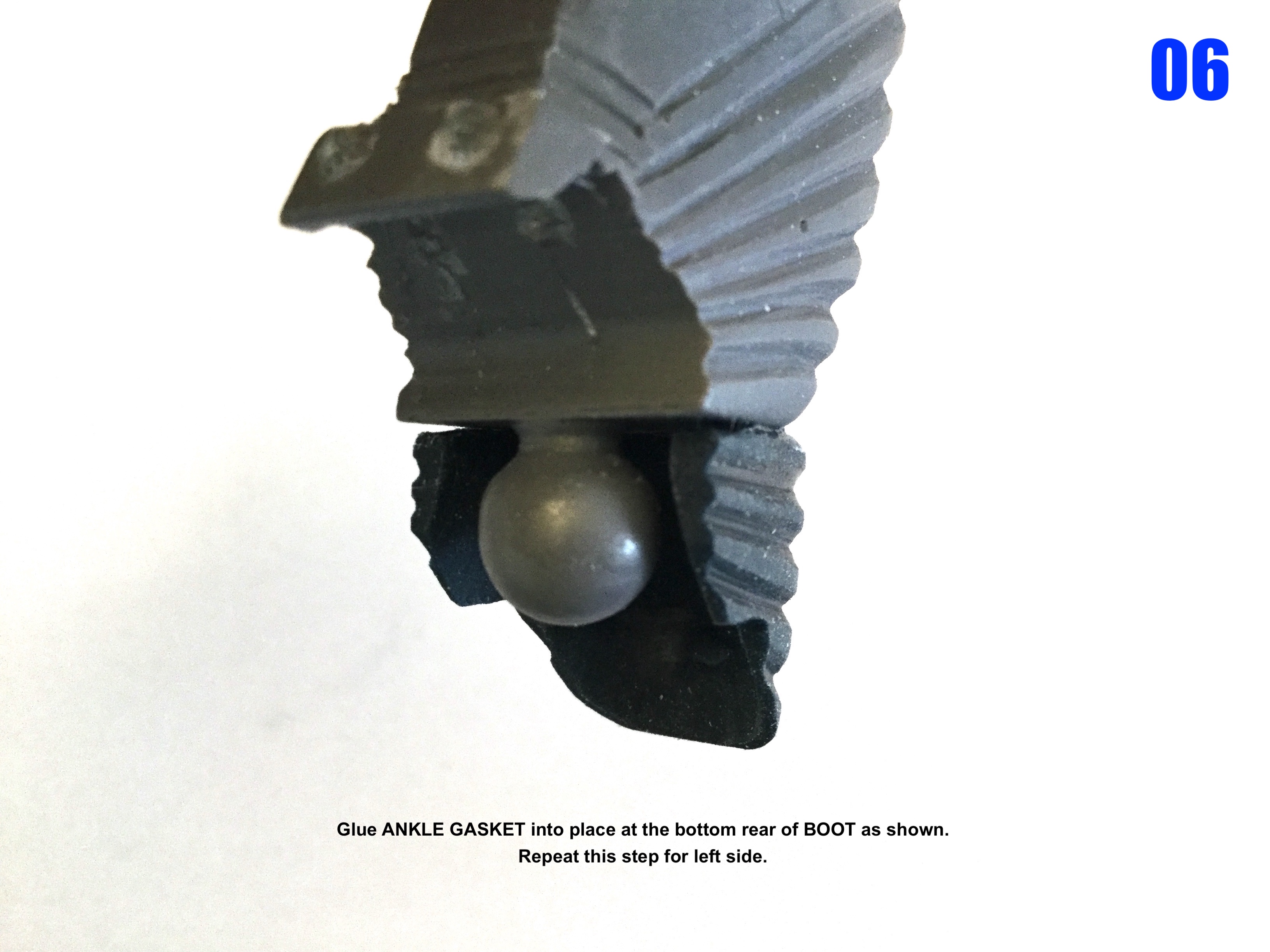
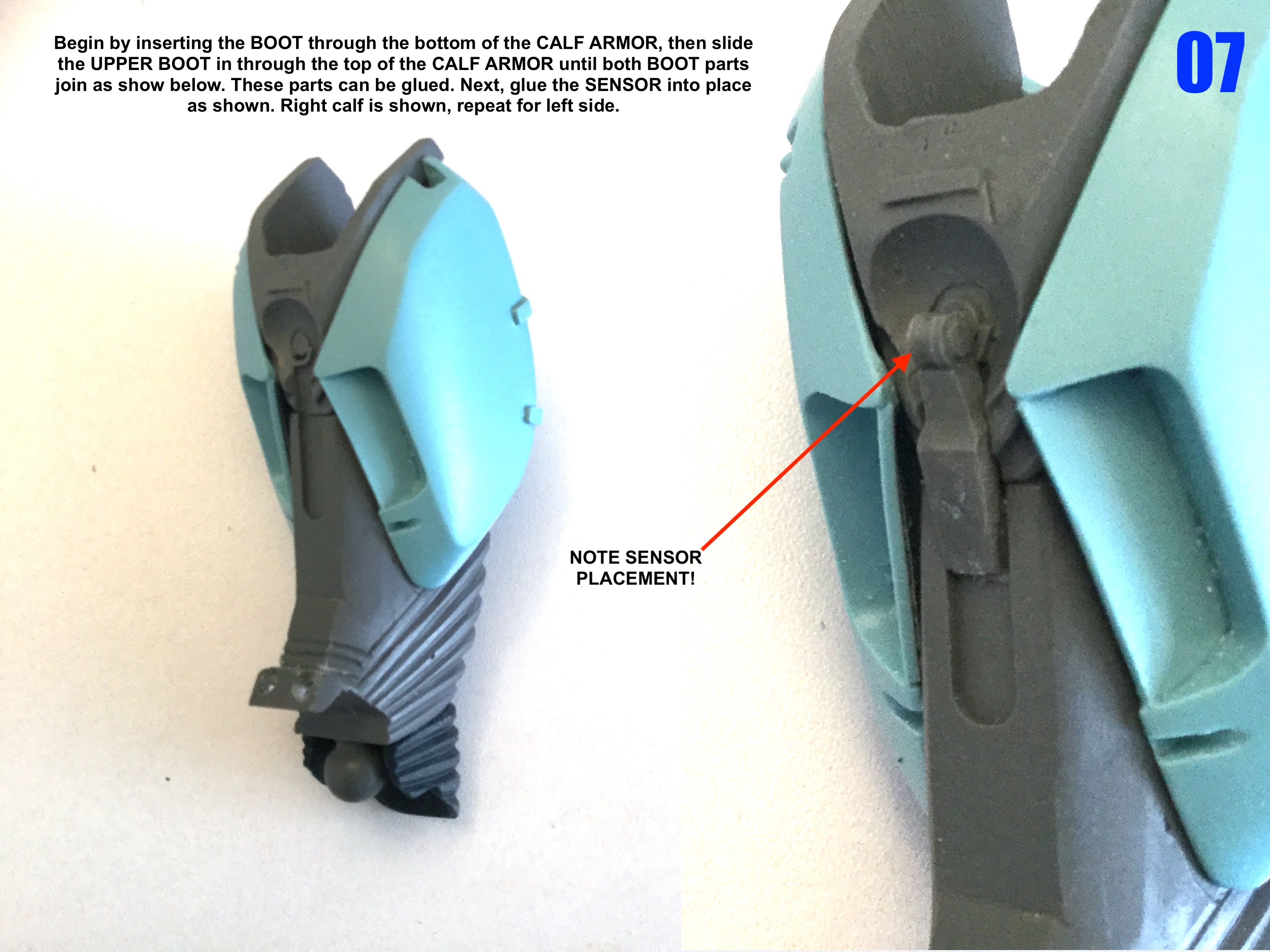
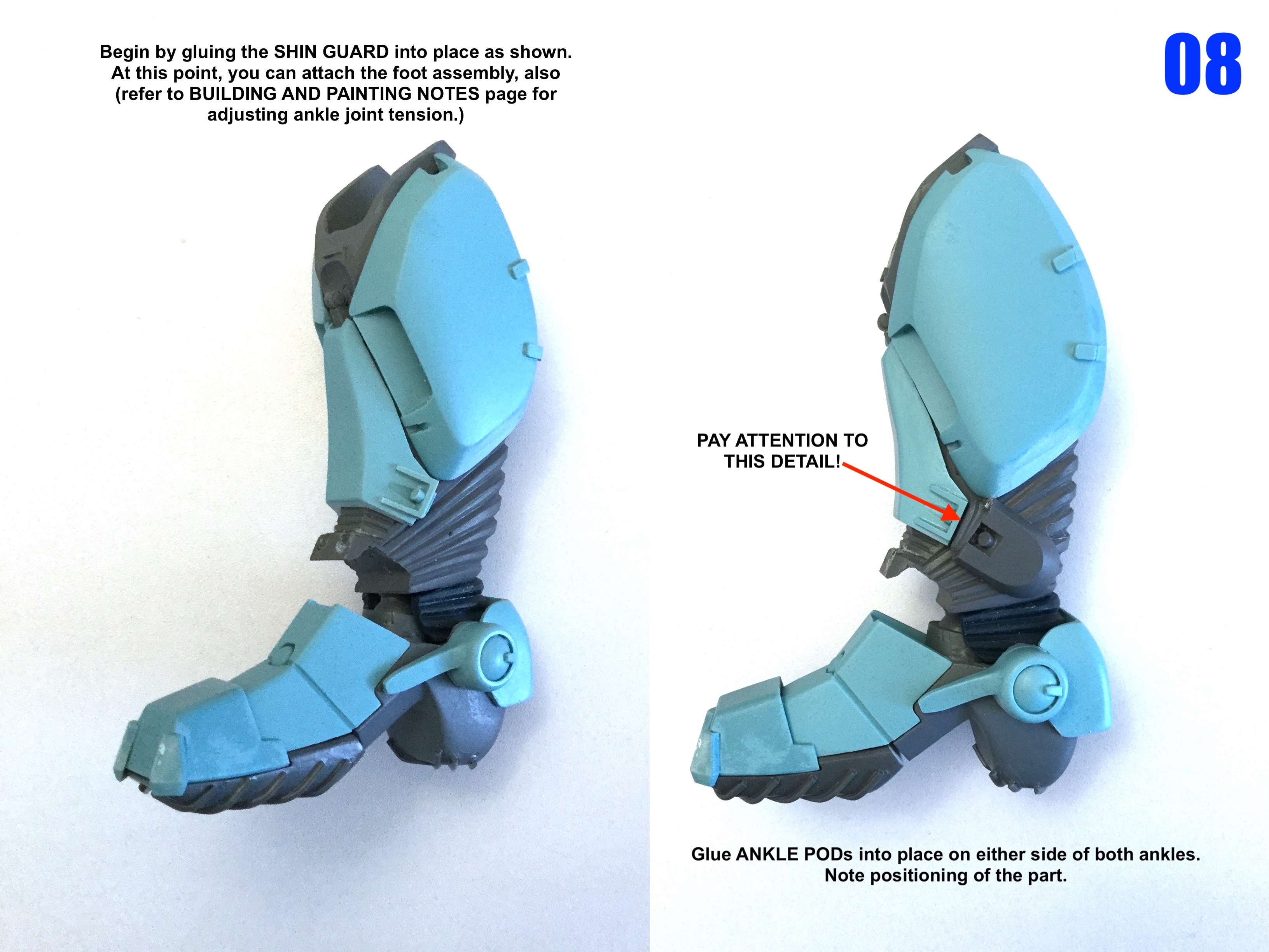
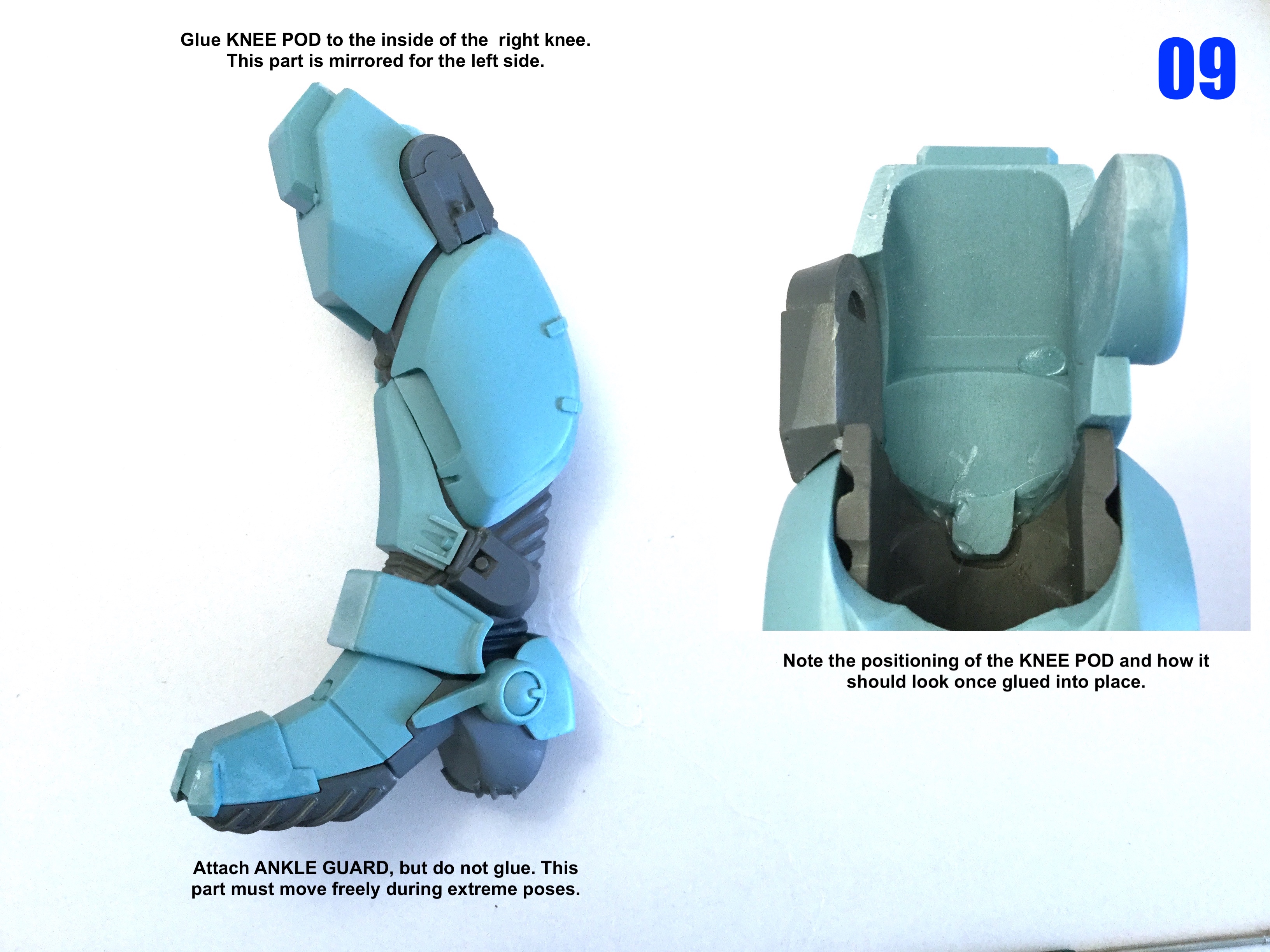
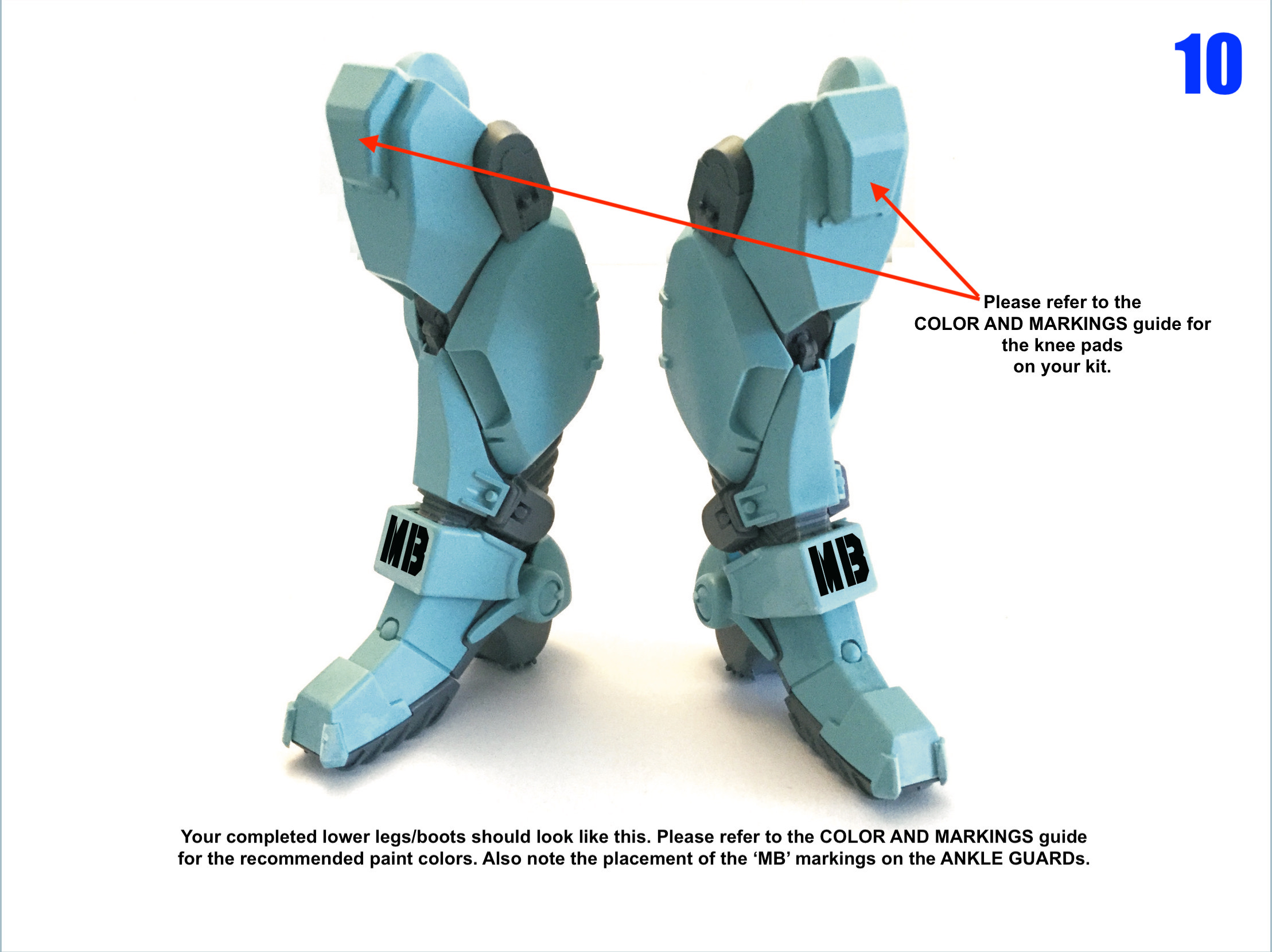
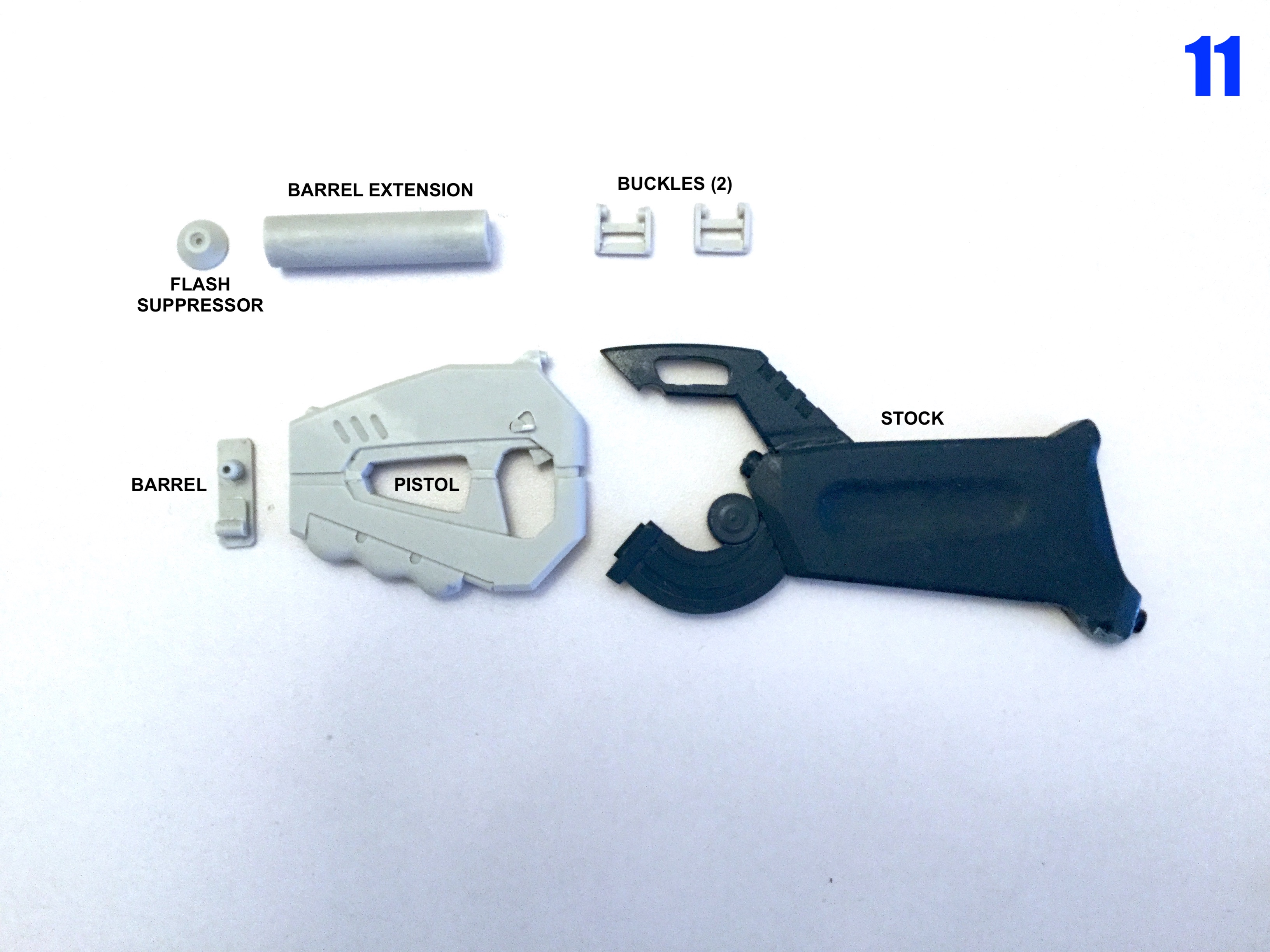
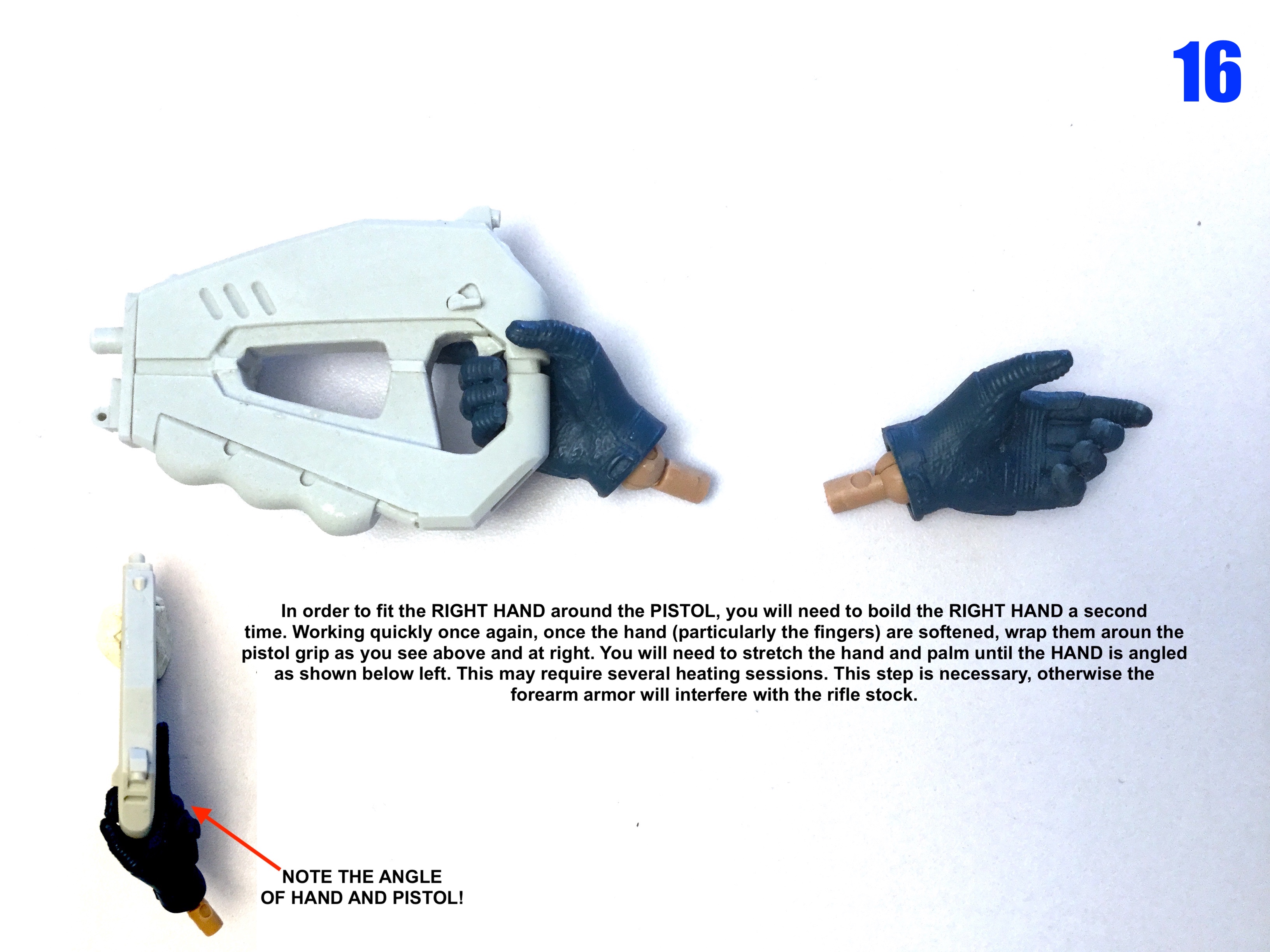
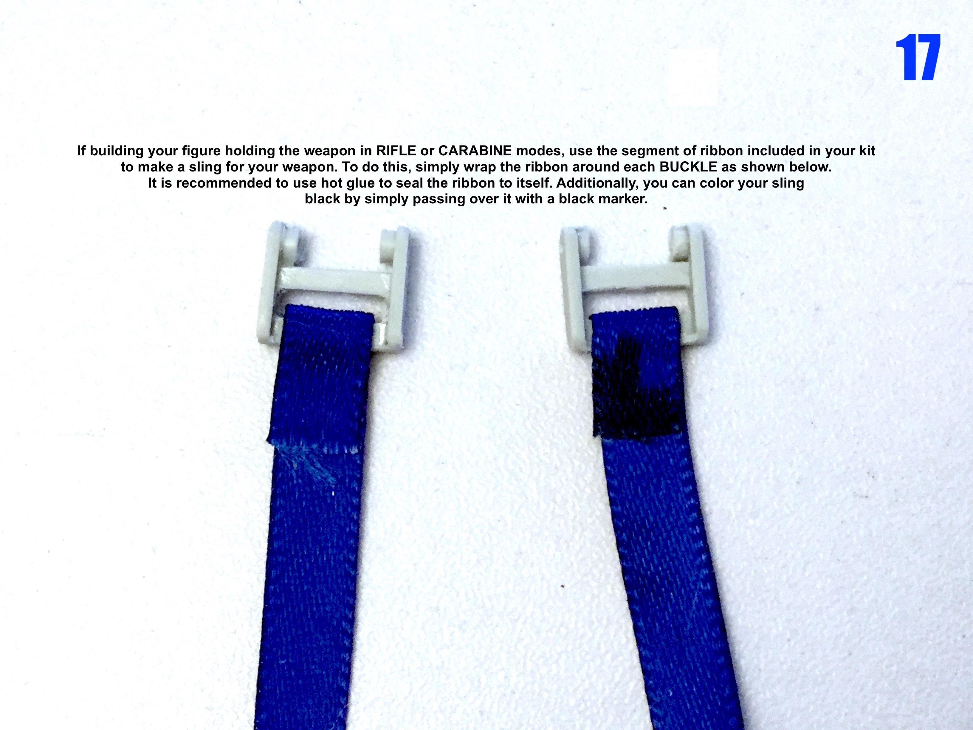
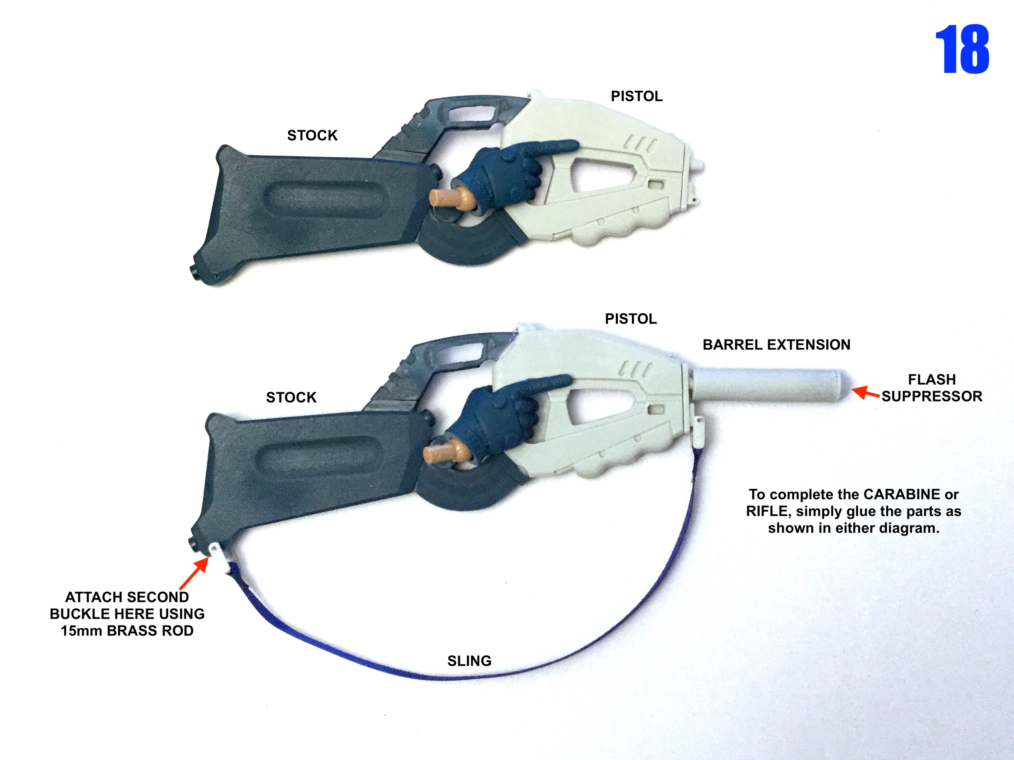
Instructions are done! Just waiting on the box art to ship.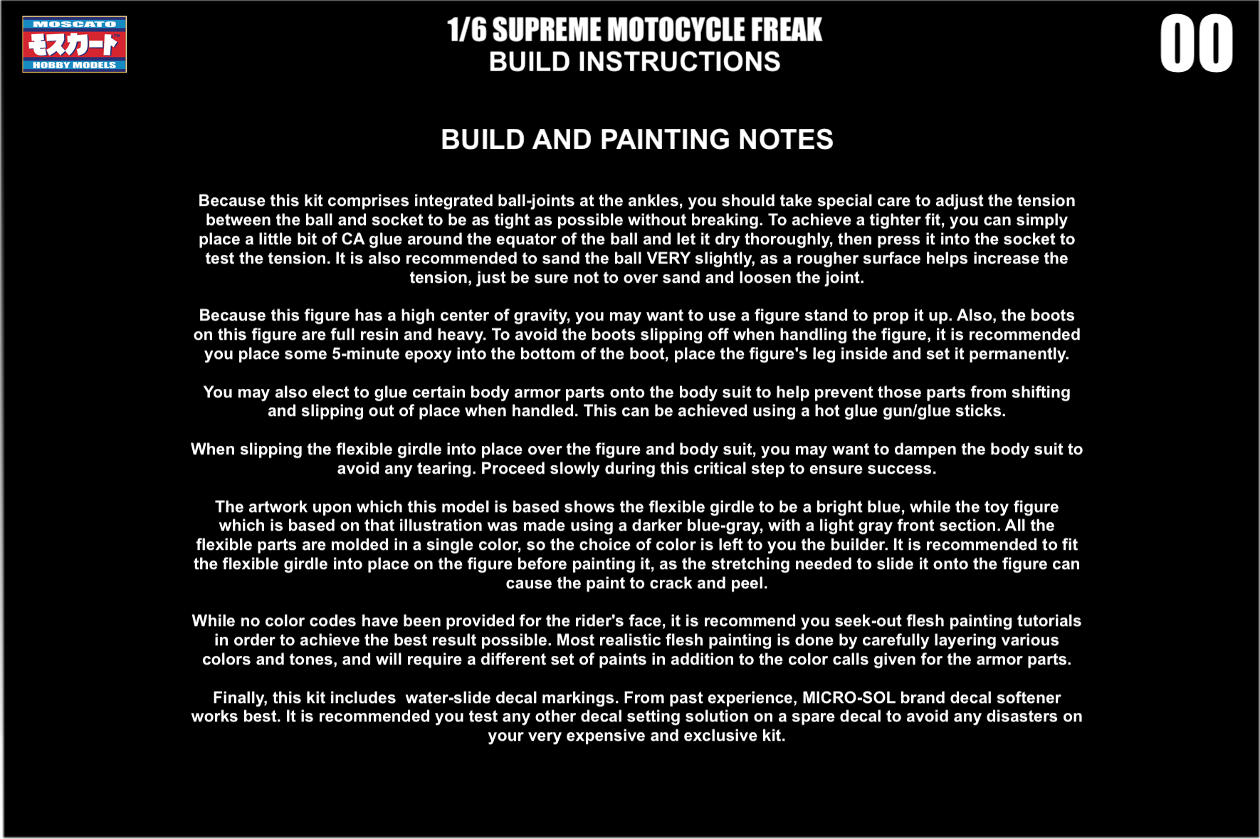
-
1/6 MOSPEADA Rider Project Proposal
captain america replied to captain america's topic in Anime or Science Fiction
-
I can't help but wonder if that isn't a cost-cutting production measure for the figure.
-
1/6 MOSPEADA Rider Project Proposal
captain america replied to captain america's topic in Anime or Science Fiction
Kits are almost ready, and I should be shipping later next week.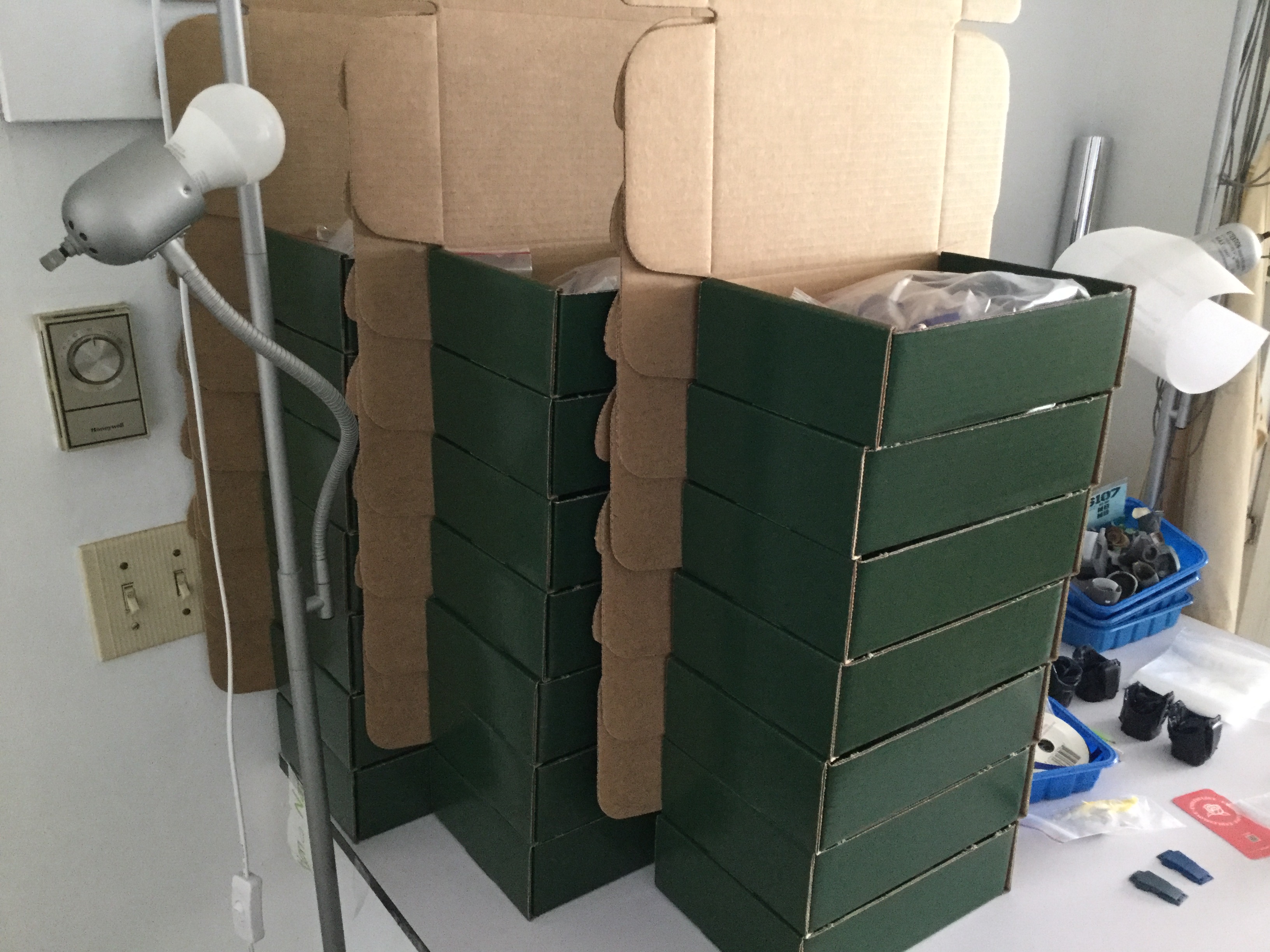
-
1/6 MOSPEADA Rider Project Proposal
captain america replied to captain america's topic in Anime or Science Fiction
You're welcome. Admittedly, you all got mostly the highlight reel, but what wasn't captured for the sake of time was the seemingly unending and tedious mold preparation, at least two mold "malfunctions", issues with demolding the flexible parts, and the almost 20 lbs of silicone mold material I had to expend to get everything to cast nicely. Truly a challenging project with many curve balls. -
1/6 MOSPEADA Rider Project Proposal
captain america replied to captain america's topic in Anime or Science Fiction
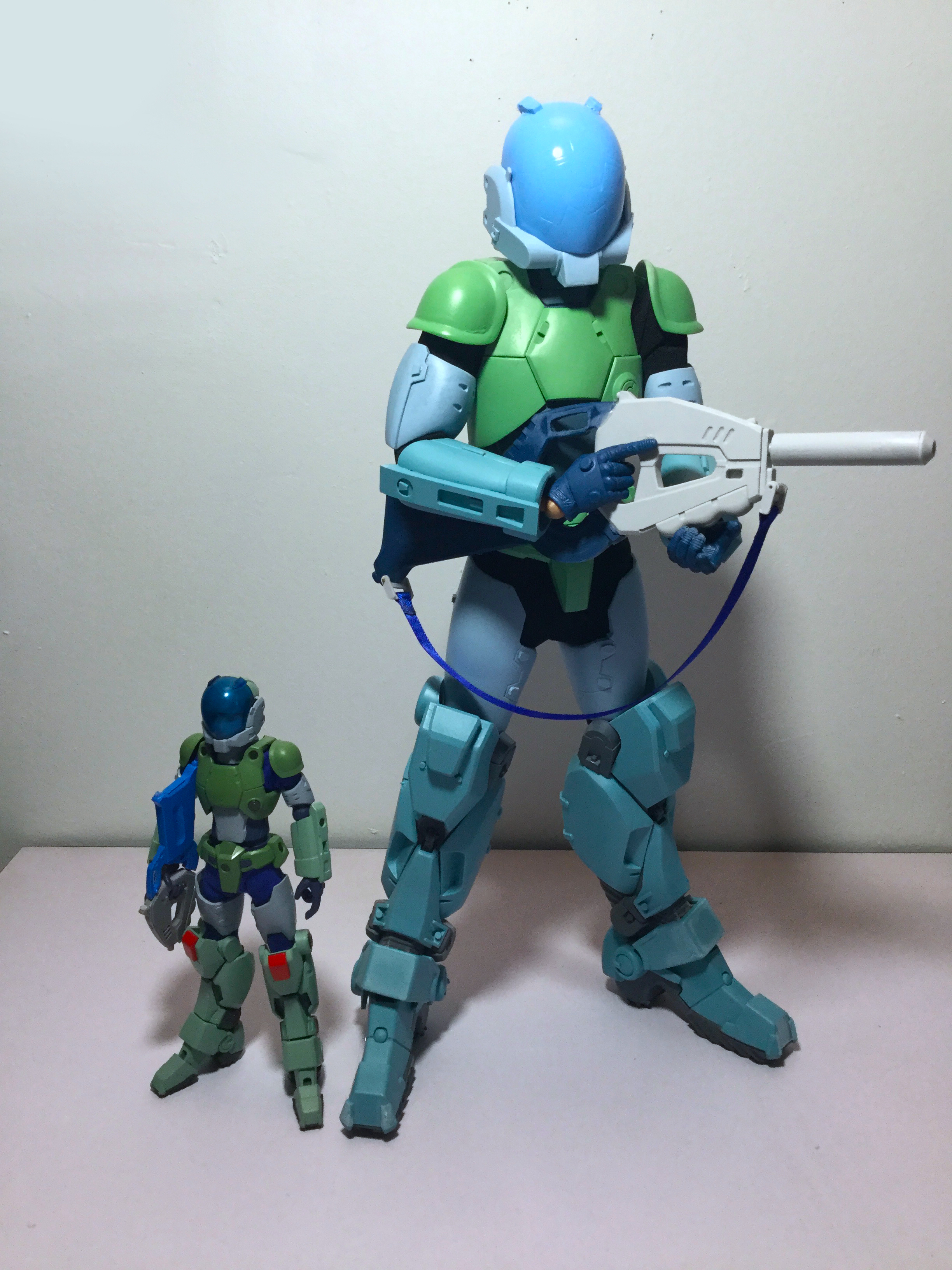
It's crazy how much modern Japanese toy designers insist on using below-average height measurements for their hero figures. 😆 -
1/6 MOSPEADA Rider Project Proposal
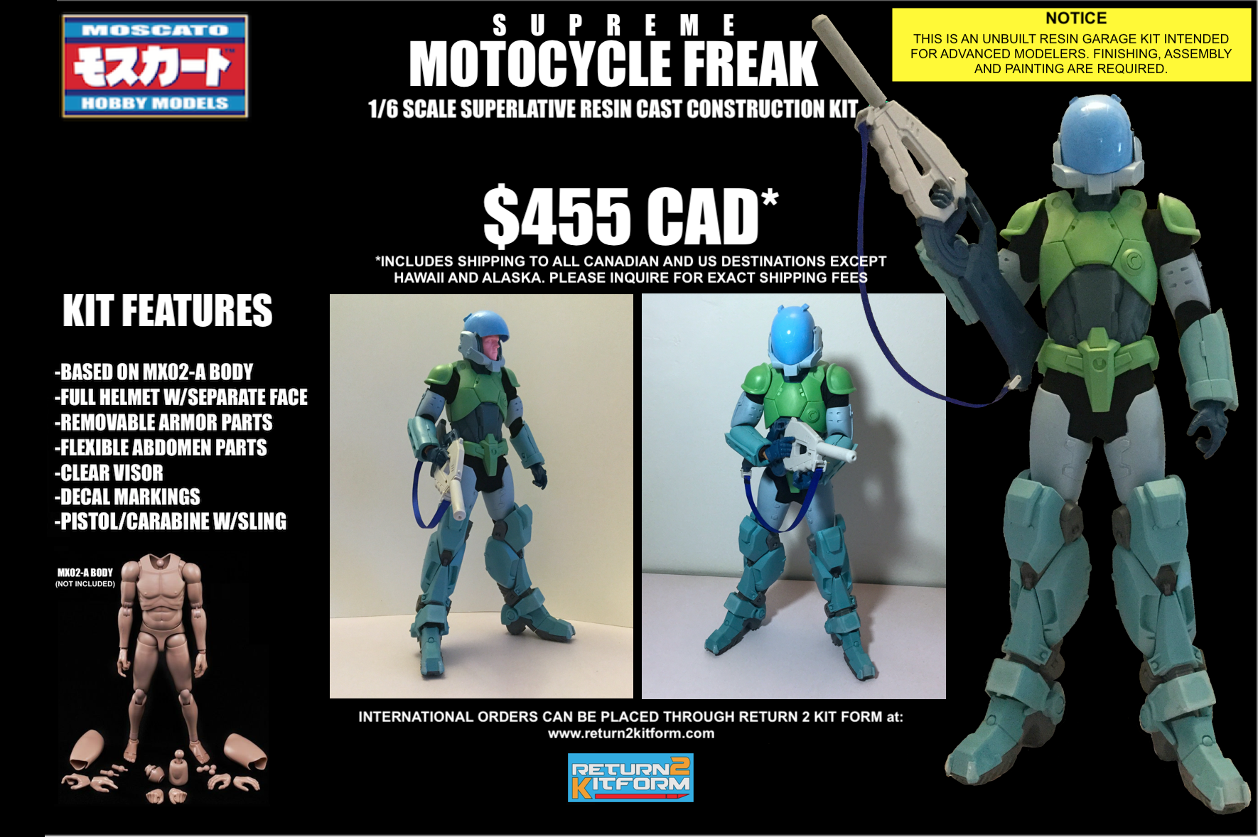
captain america replied to captain america's topic in Anime or Science Fiction
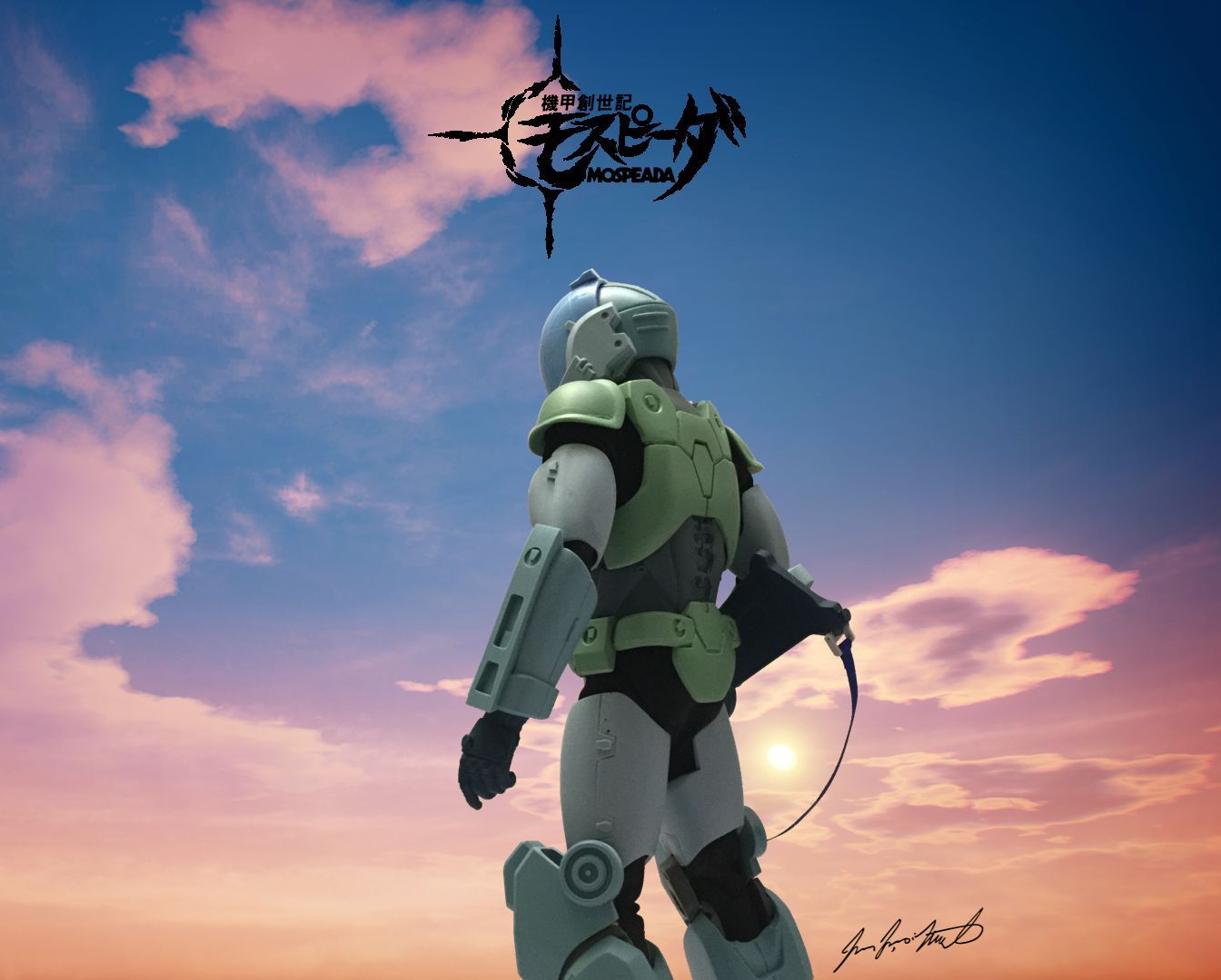
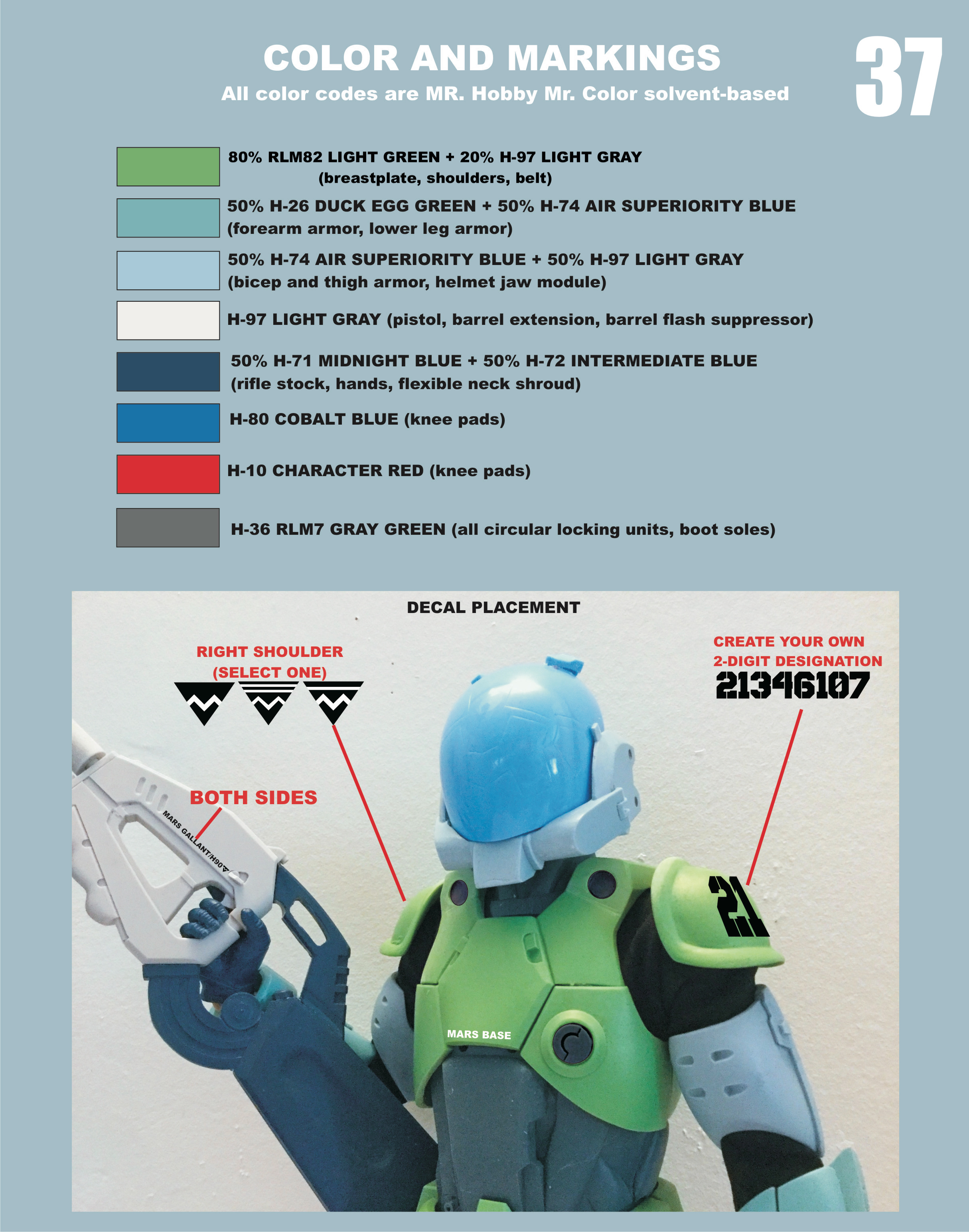
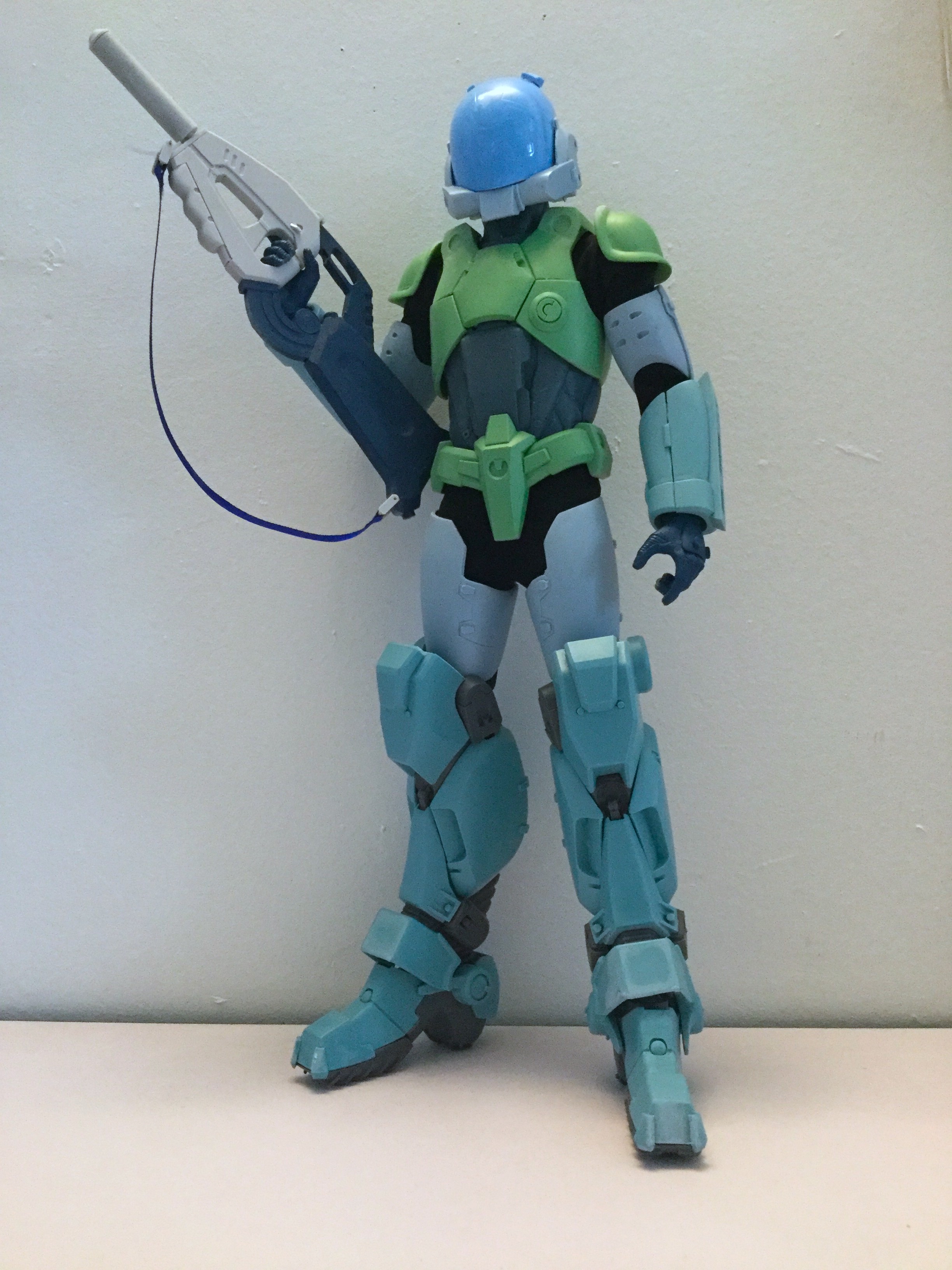
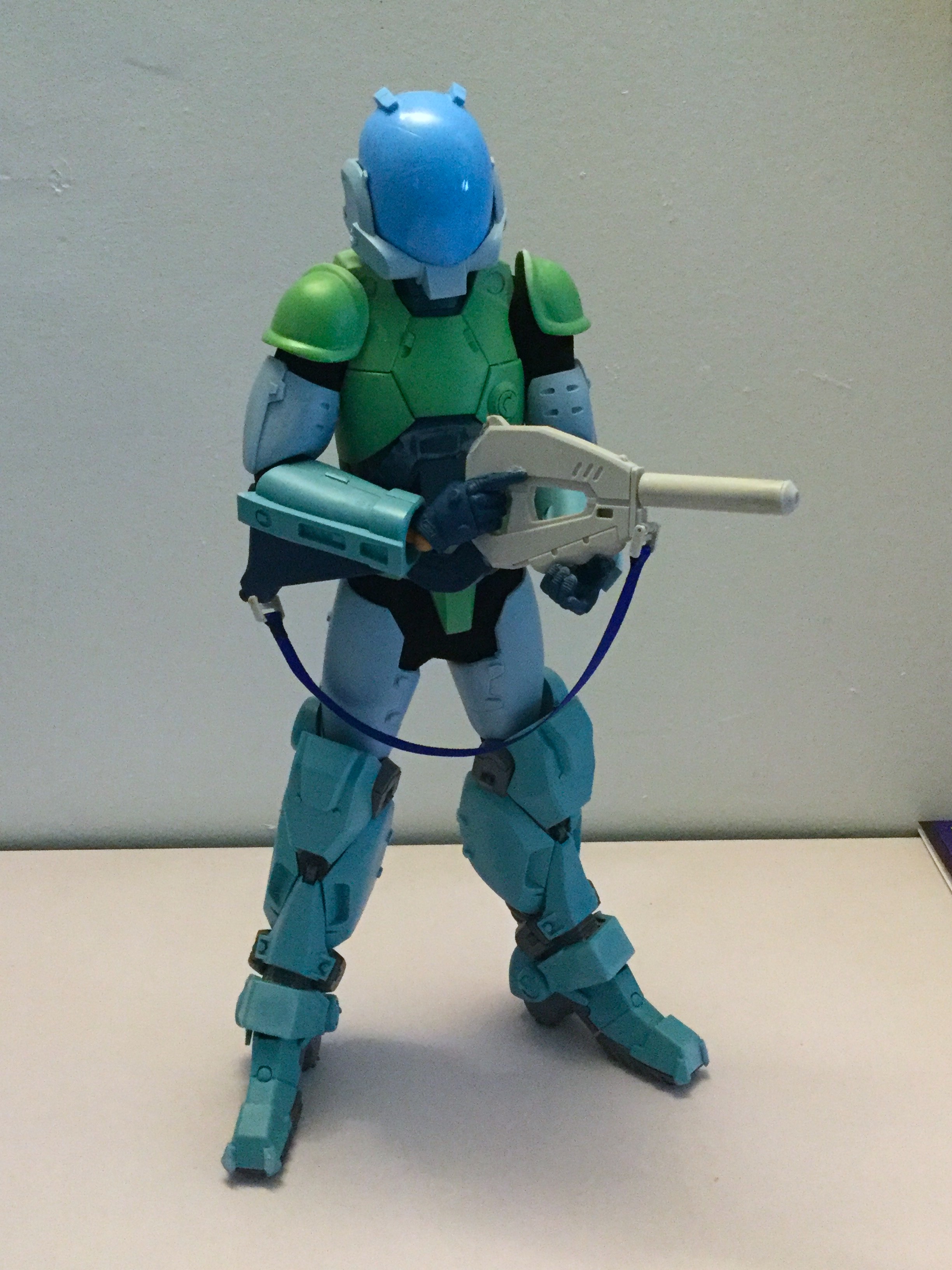
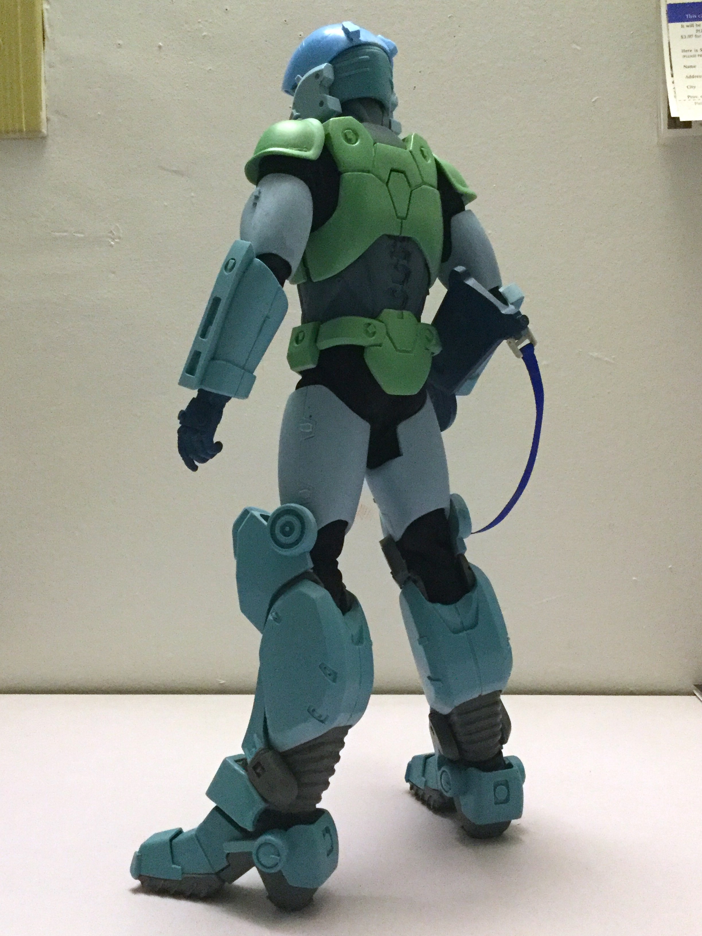
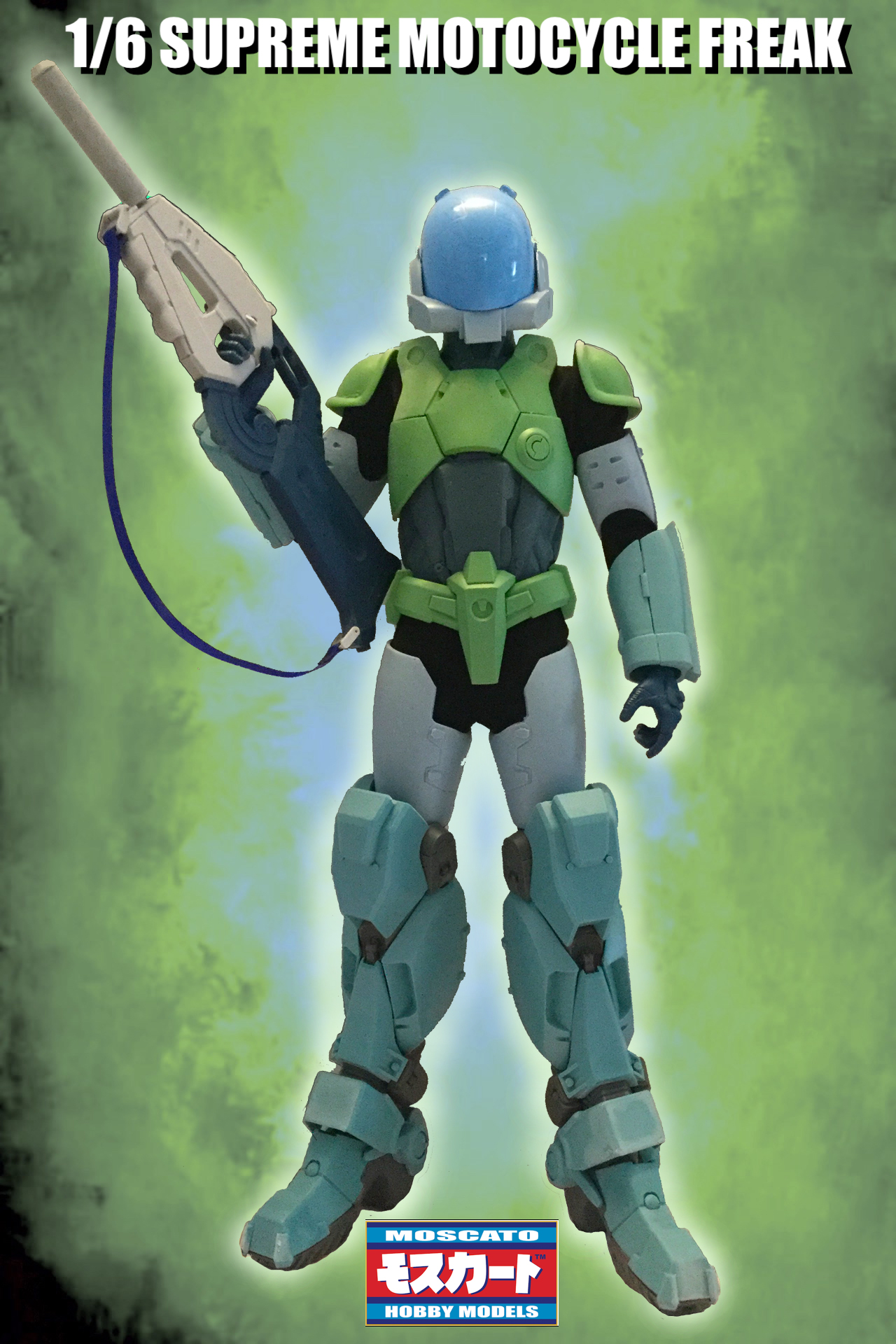
Behold: the Supreme MOSPEADA battle suit. The visors will be clear blue, just like on the 1/12 accessories, this is just a mock-up barely holding together with temporary adhesive.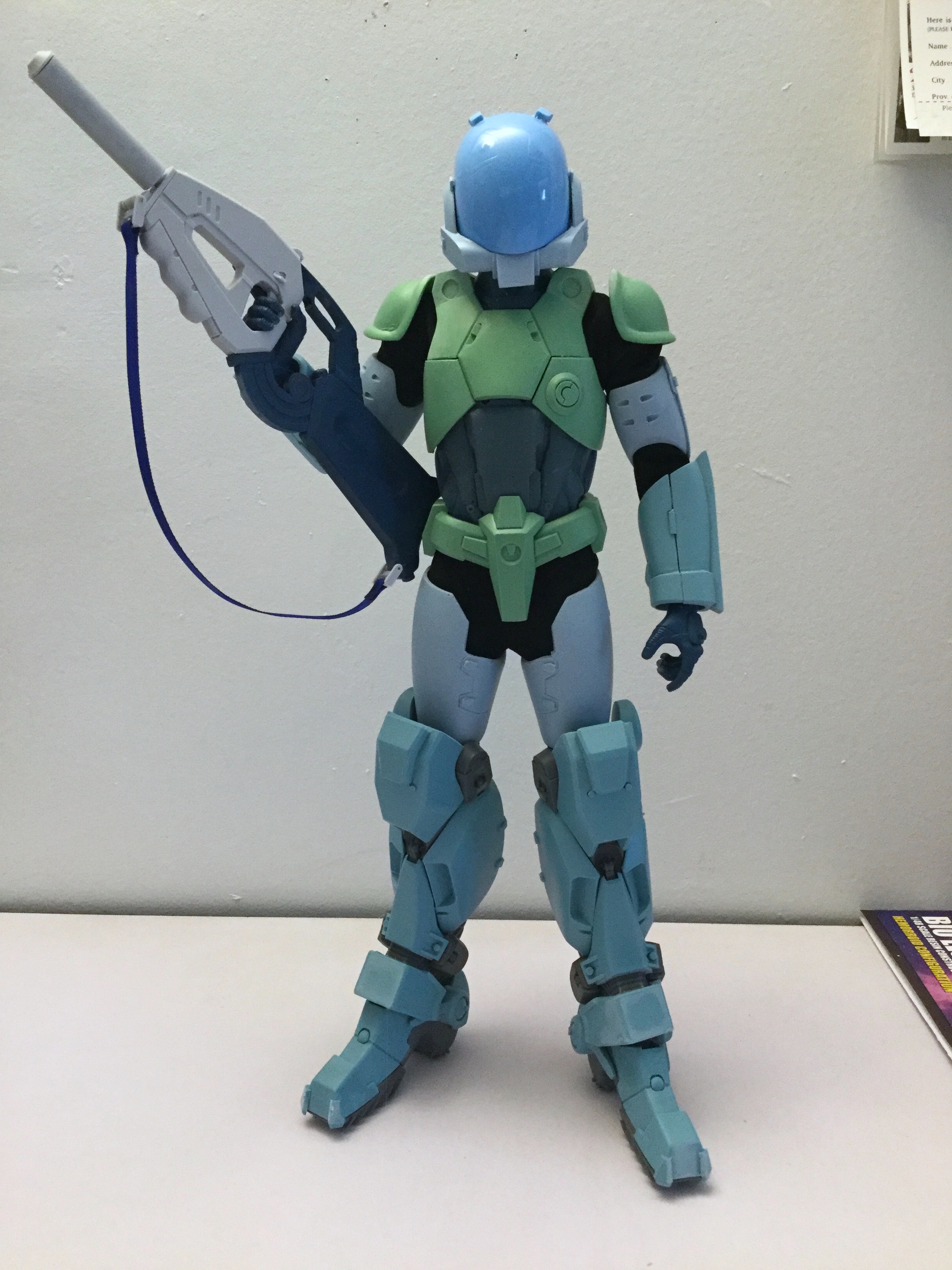
-
1/6 MOSPEADA Rider Project Proposal
captain america replied to captain america's topic in Anime or Science Fiction
Tomorrow it will be revealed.