captain america
-
Posts
3537 -
Joined
-
Last visited
Content Type
Profiles
Forums
Events
Gallery
Everything posted by captain america
-
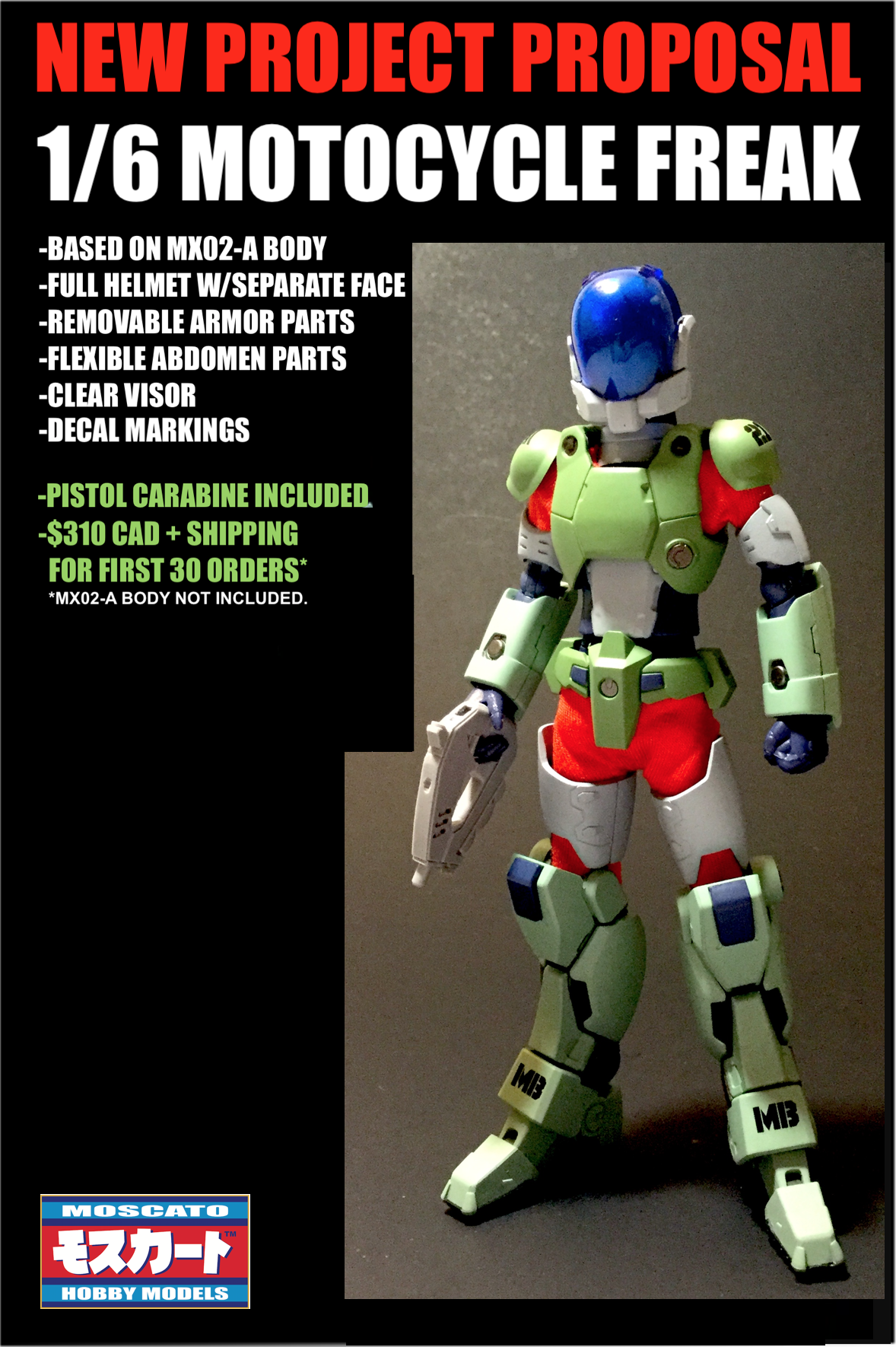
New Moscato Hobby Models project proposal: 1/6 Motocycle Freak. The kit would consist of all the body armor for the rider, designed to fit a MX02-A figure. The head will come with a separate, realistic (non-anime) removable face and posable visor. Abdomen parts would be molded in flexible material for better posing mobility. Decal markings will be included, as well as gloved hands. The pre-order (first 30 kits) will include the rifle/stock/barrel, which will be extra once the pre-orders are filled. Please note that the MX02-A figure body is not included. You'll need that and the onesie of your preferred color to complete the build. Price: $310 Canadian + shipping. The project will only go ahead if I can fill all 30 spots. Please post 'WANT' only if you're serious about making a purchase for this. Any post that doesn't meet the previous criteria will not be counted. So what say you?
-

1/48 SOUTHERN CROSS BIOROID PART II
captain america replied to captain america's topic in Anime or Science Fiction
*Heavy breathing intensifies* 😛 -
The Unlicensed Third Party Transformers Thread
captain america replied to slaginpit's topic in Anime or Science Fiction
What I'd like to know... is this figure bare plastic, or is it painted with a matte finish? -
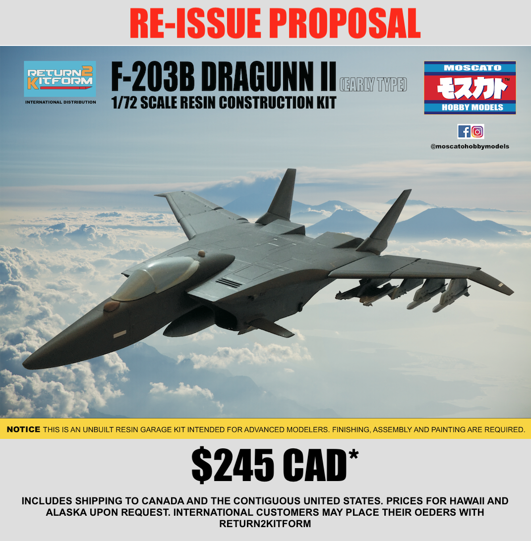
1/72 F203 Dragon II Kit Proposal --Moscato Hobby
captain america replied to captain america's topic in Model kits
Seeing as how Wave covered the VF-4, I don't see the point in offering a resin kit of it. They dropped the ball on the clumsy surface details, but I don't think that warrants paying 50% more to solve. Frankly, I'd rather offer an F-203E ground attack, 2 seater variant with bomb payload. -
1/72 F203 Dragon II Kit Proposal --Moscato Hobby
captain america replied to captain america's topic in Model kits
Re-issue is scrubbed. Maybe in a few years. -
Great build! That kit brings back a lot of memories, and I enjoy seeing people bring my kits to life. We need 1/48 Destroids!
-
1/72 F203 Dragon II Kit Proposal --Moscato Hobby
captain america replied to captain america's topic in Model kits
-
1/72 F203 Dragon II Kit Proposal --Moscato Hobby
captain america replied to captain america's topic in Model kits
Tick-tock. I'll leave the pre-order window open until the end of the day on September 12th. Hopefully I'll get the needed tally of 12 kits by then, and if not, I'll go to another project. -
1/48 SOUTHERN CROSS BIOROID PART II
captain america replied to captain america's topic in Anime or Science Fiction
I think I've given-up on Anime accuracy with anything to do with the Bioroids. It's all just biomechanical gummy bears, jellybeans and jello as far as I'm concerned. The style-guide artists bear the guilt, and the animators commit yet greater atrocities, still! Nonetheless, I look forward to seeing the build progress. Judging from the Biopsycher knee pics, you're further along on that one than the Bug Face unit. -
1/48 SOUTHERN CROSS BIOROID PART II
captain america replied to captain america's topic in Anime or Science Fiction
Hey, Ted. I so enjoy seeing your building progress, especially that these Lloyds are some of my best work and very challenging models to build. I would have liked to offer visor pieces molded in traslucent resin, but the workload was already very high, and the lenses are just pure black in all the shots I remember, so I determined the extra complexity was unwarranted. That being said, I'm curious to see what greeblies you plan to stuff behind the vac-formed parts. Also, in case anyone is wondering...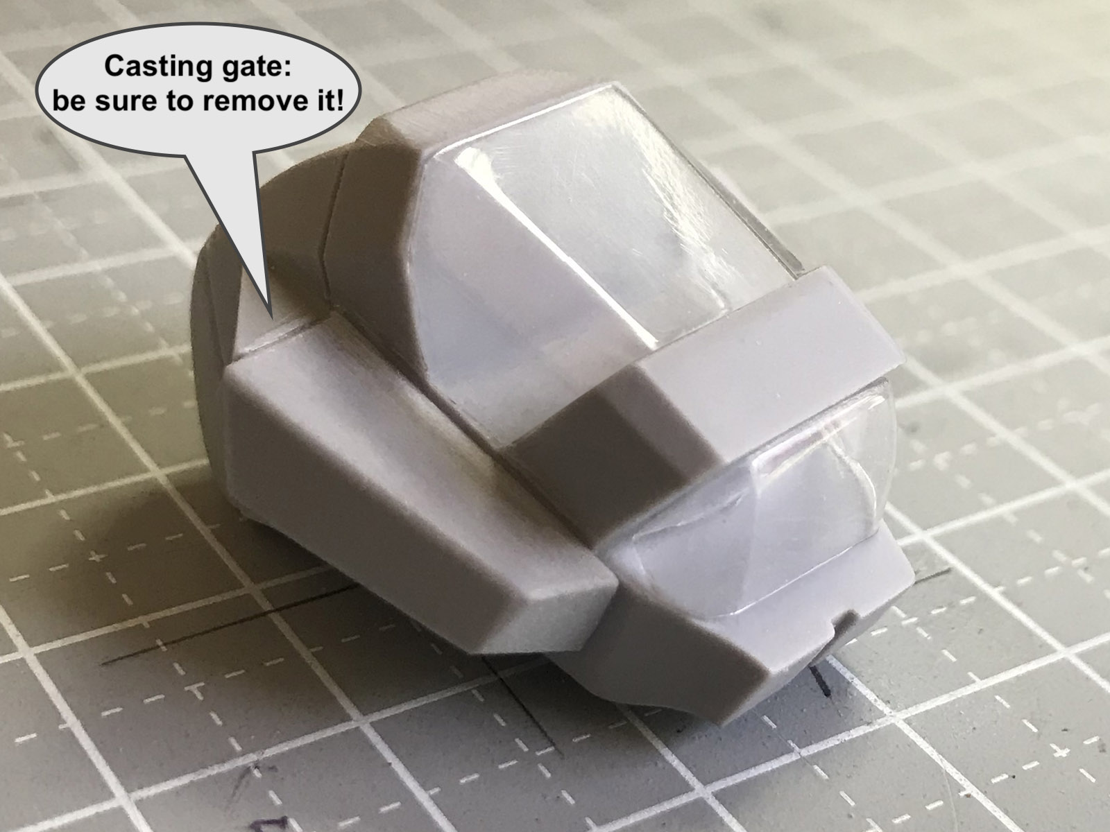
-
Top Gun: Maverick (Top Gun 2 is comin)
captain america replied to Ladic's topic in Anime or Science Fiction
-
1/72 F203 Dragon II Kit Proposal --Moscato Hobby
captain america replied to captain america's topic in Model kits
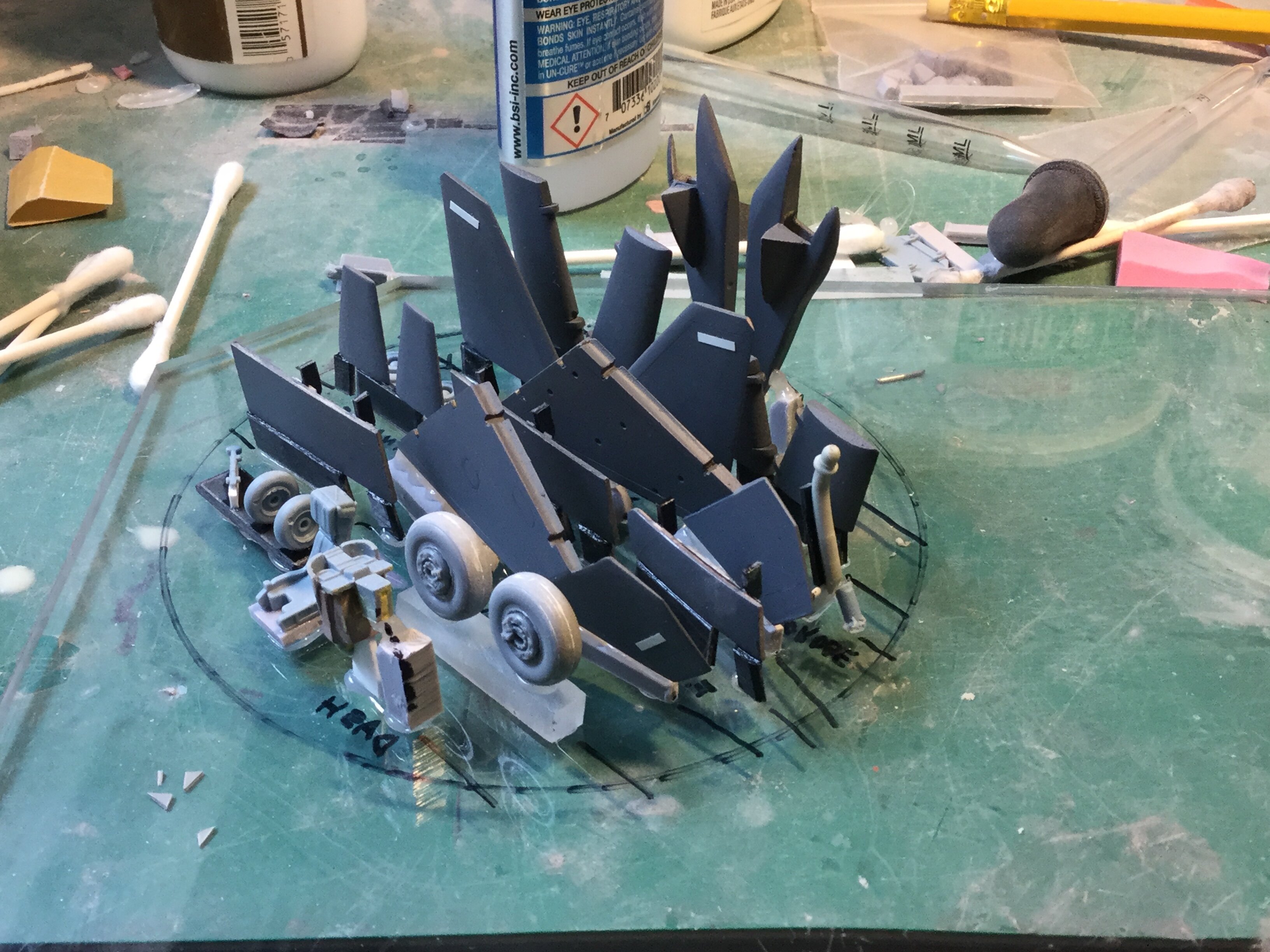
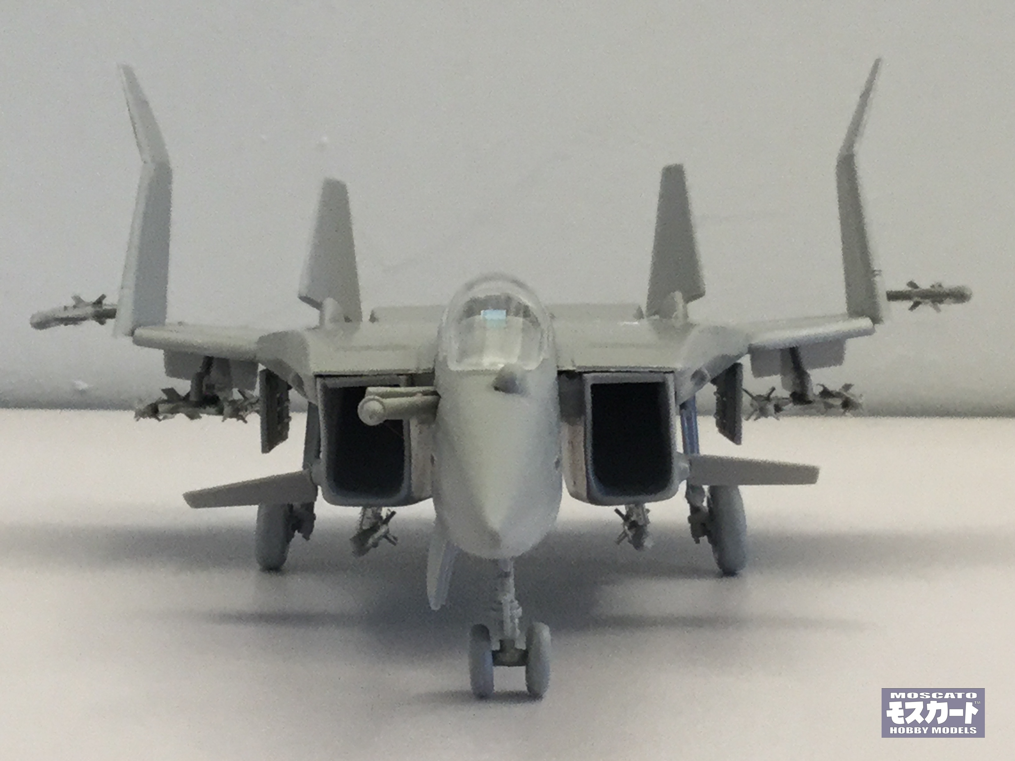
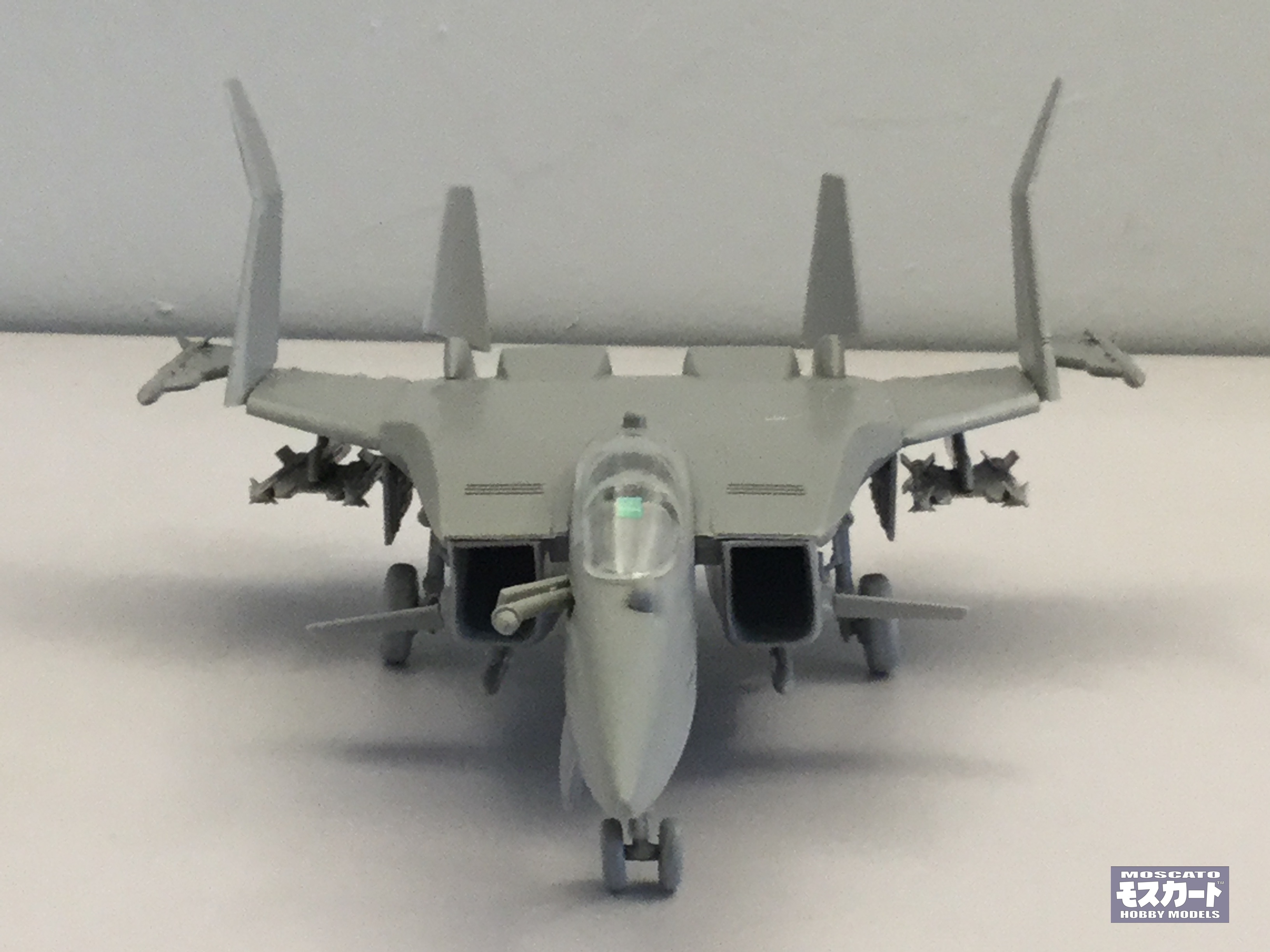
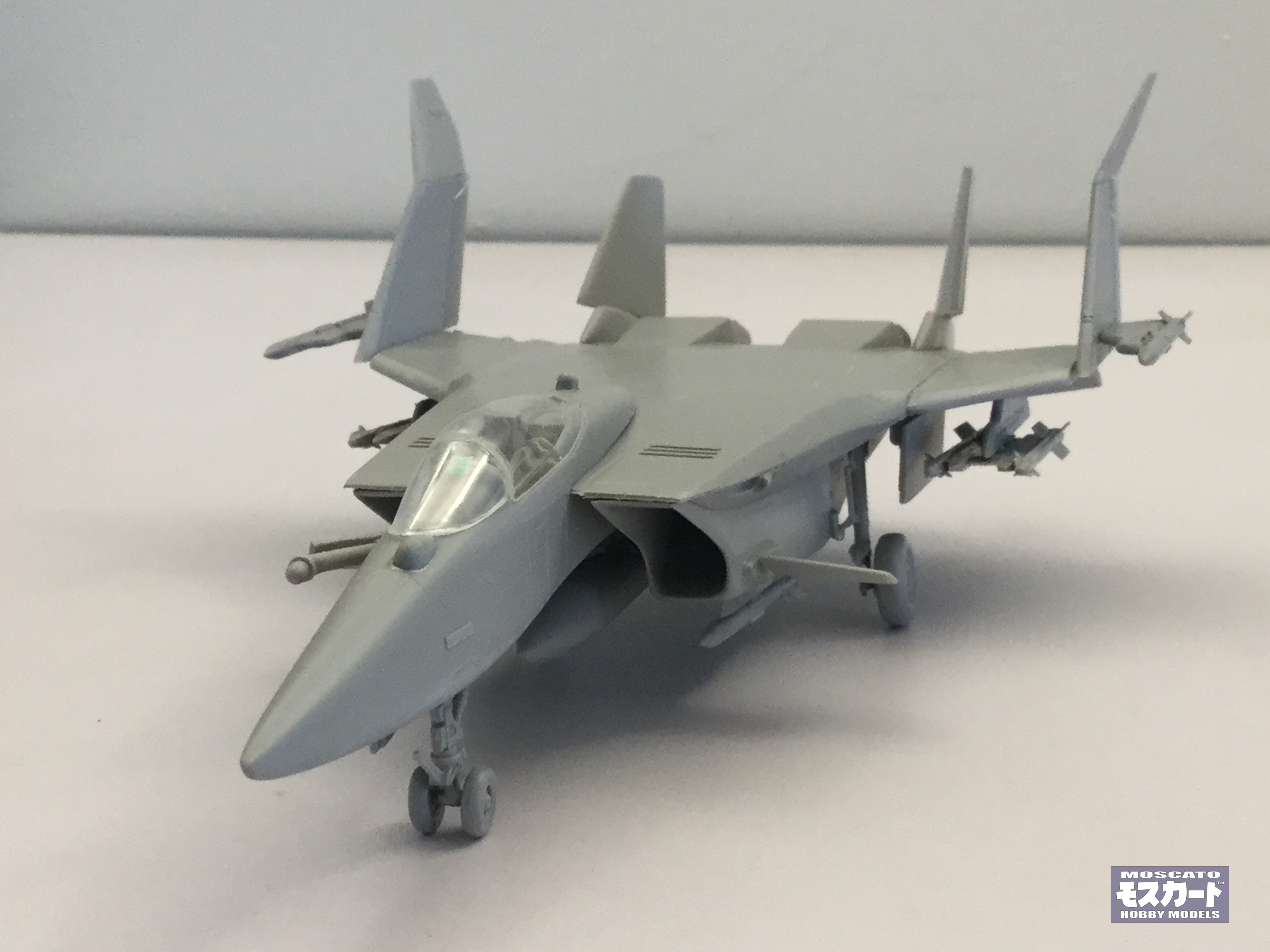
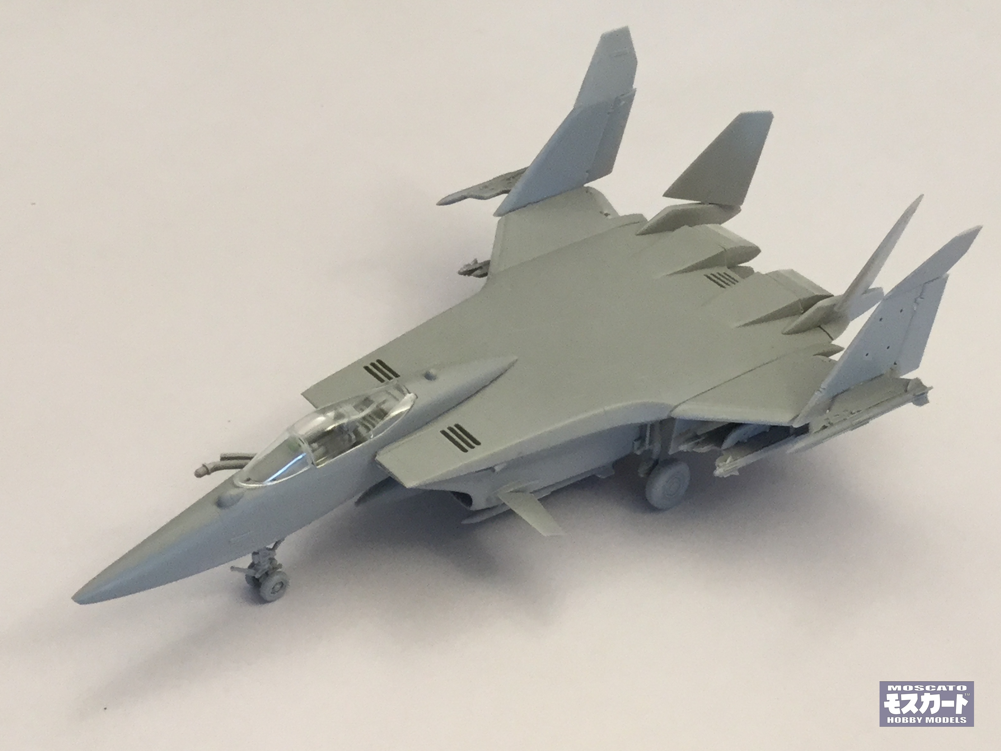
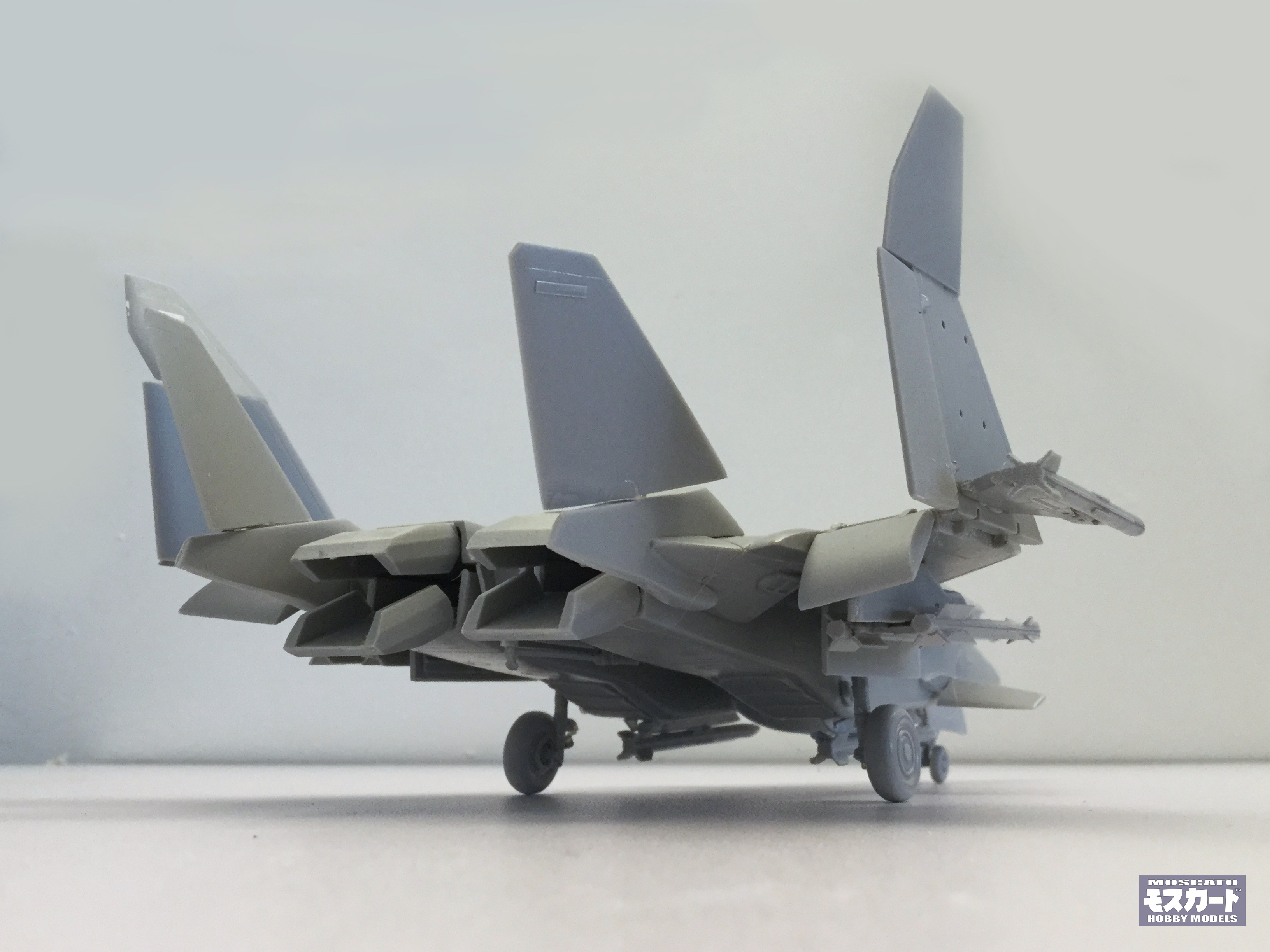
Extremely mean and dangerous! Sometimes the best projects are the throw-away designs the original art team didn't mangle. So this is me throwing my hat into the ring with an offer for a second run, this time with decals and commensurate price bump. Please forgive the rickety build, it's barely holding together with hot glue.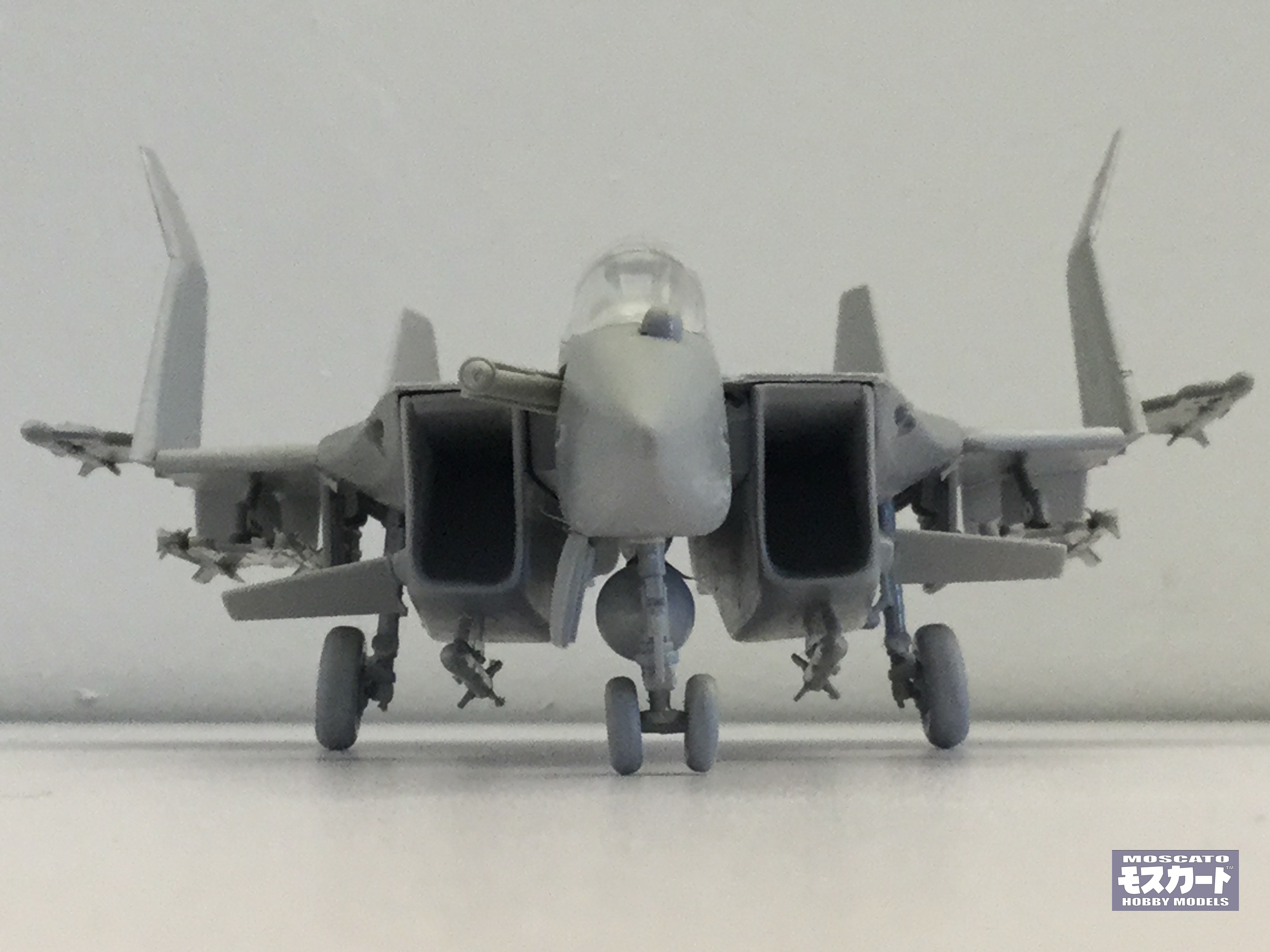

-
1/72 F203 Dragon II Kit Proposal --Moscato Hobby
captain america replied to captain america's topic in Model kits
-
1/72 F203 Dragon II Kit Proposal --Moscato Hobby
captain america replied to captain america's topic in Model kits
-
1/72 F203 Dragon II Kit Proposal --Moscato Hobby
captain america replied to captain america's topic in Model kits
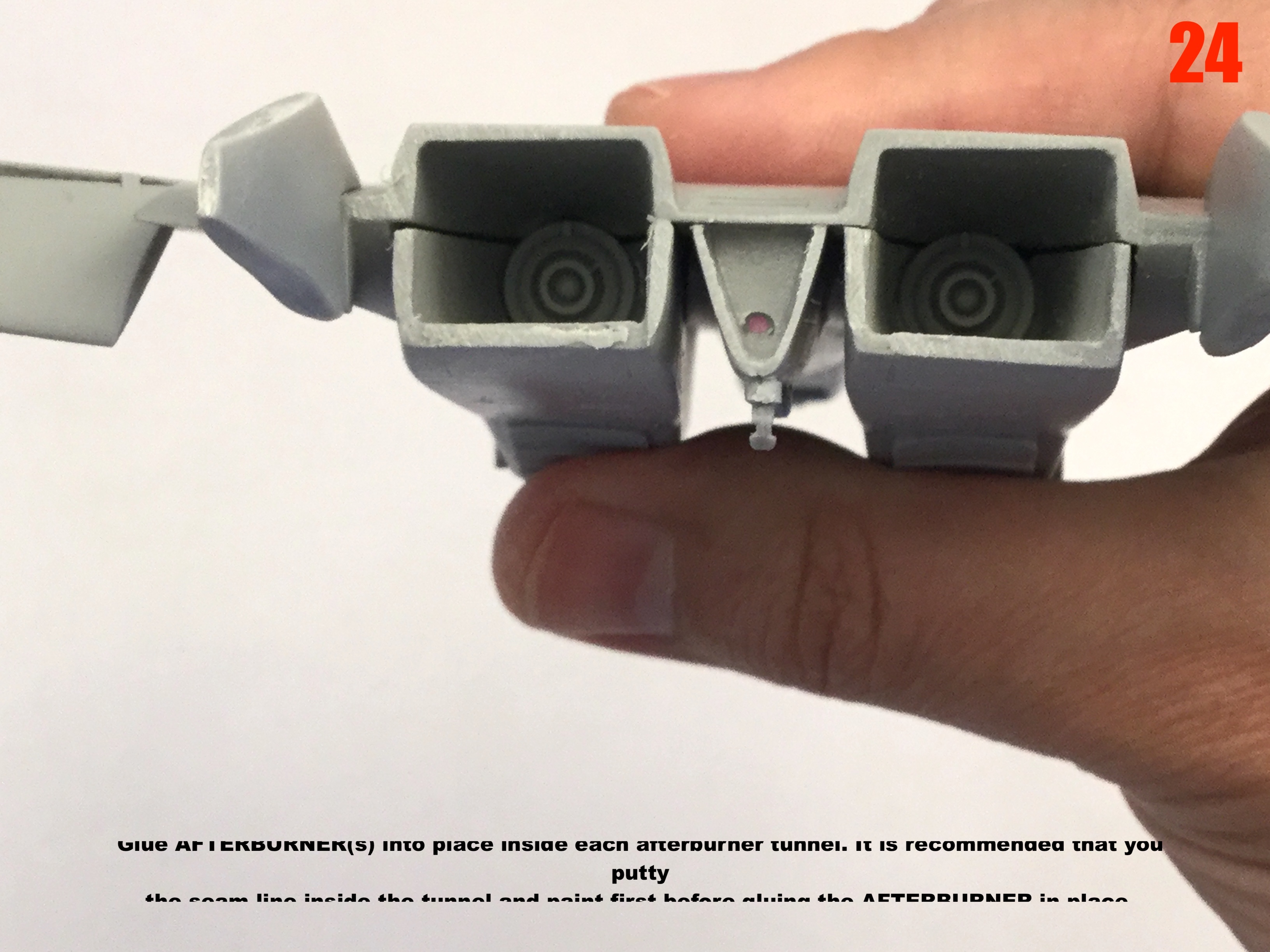
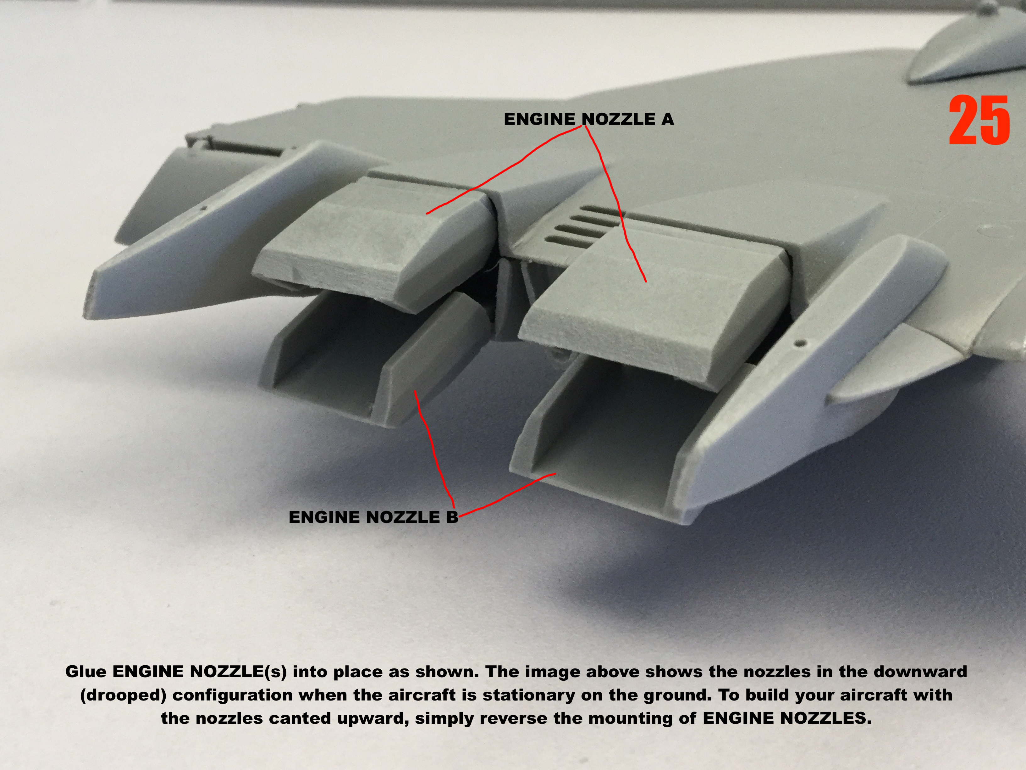
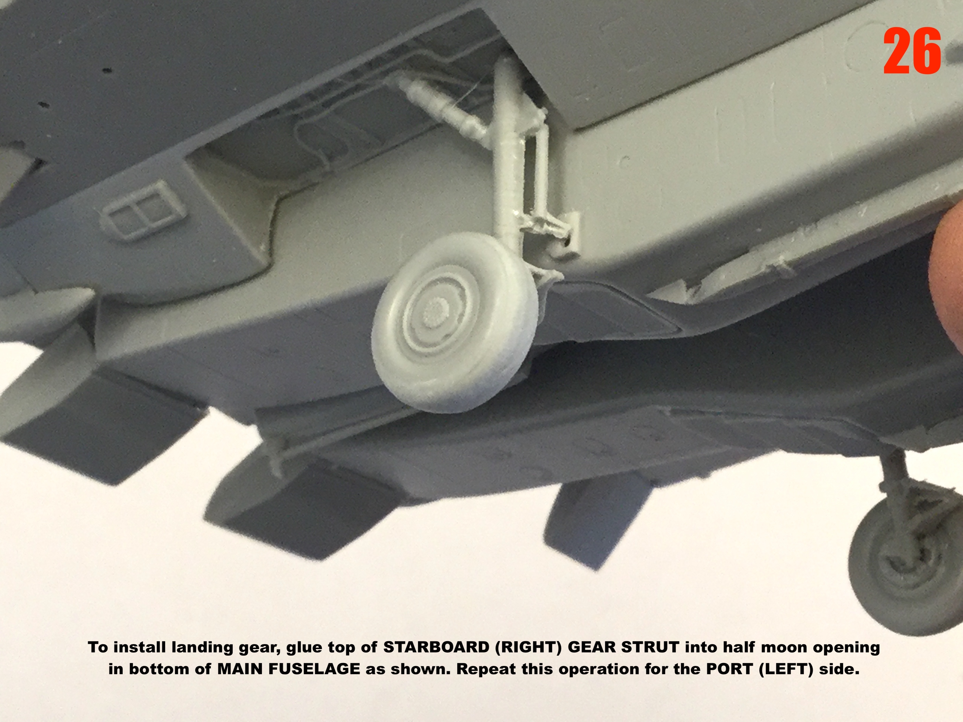
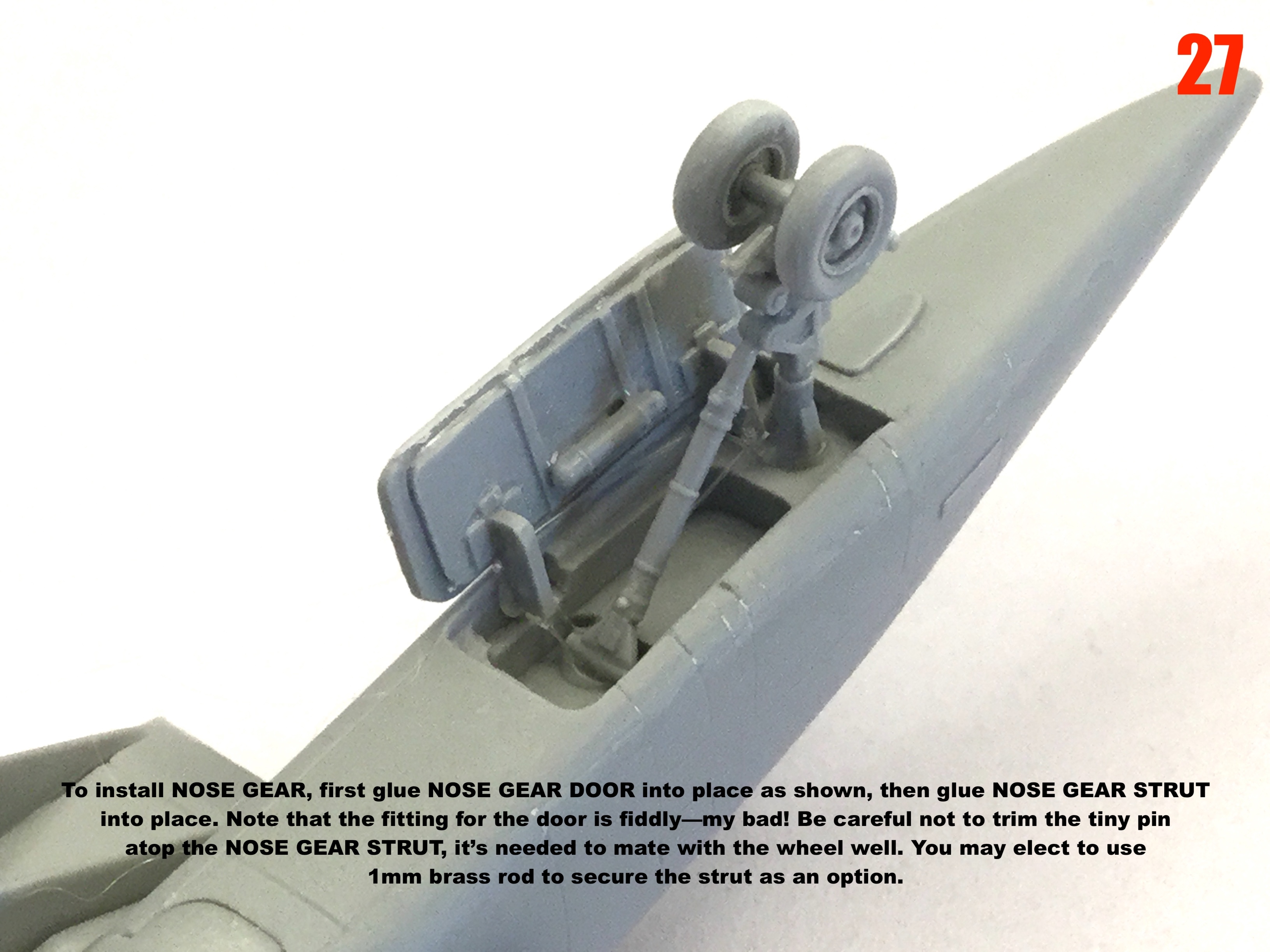
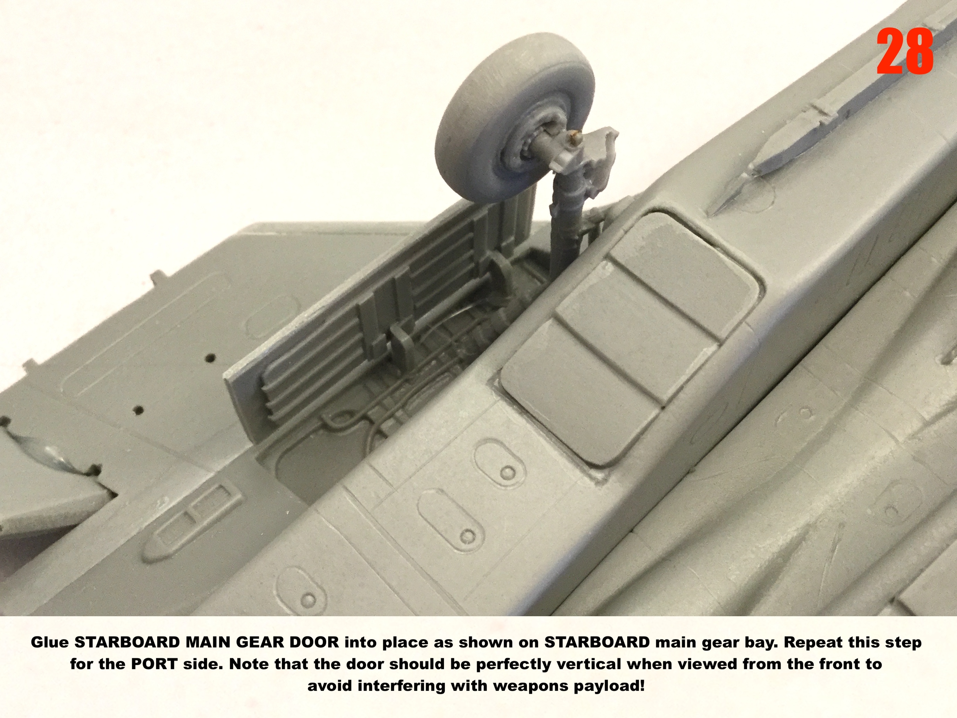
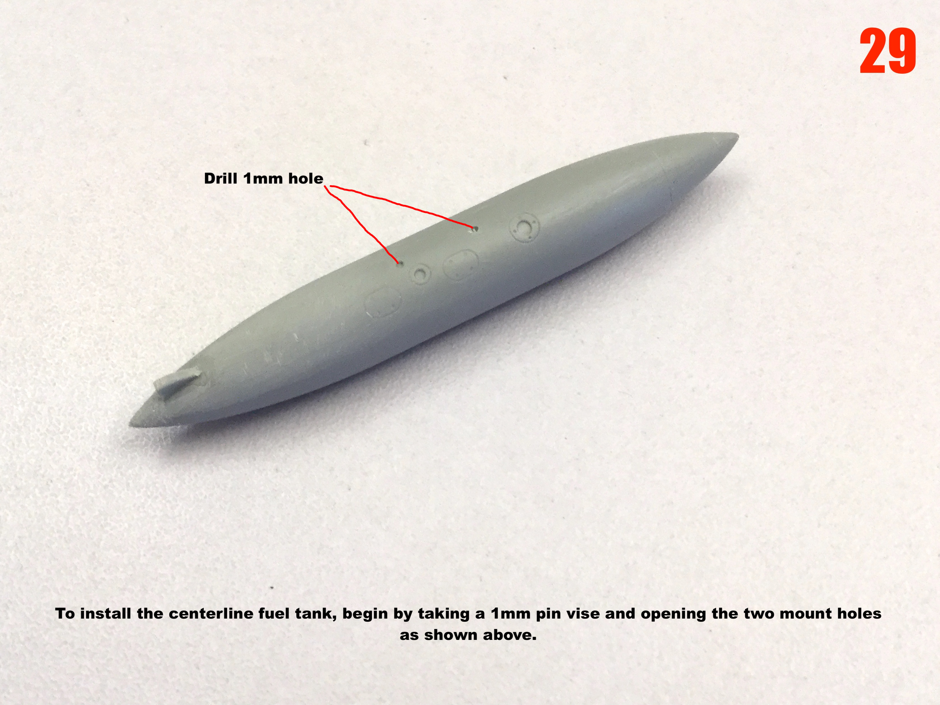
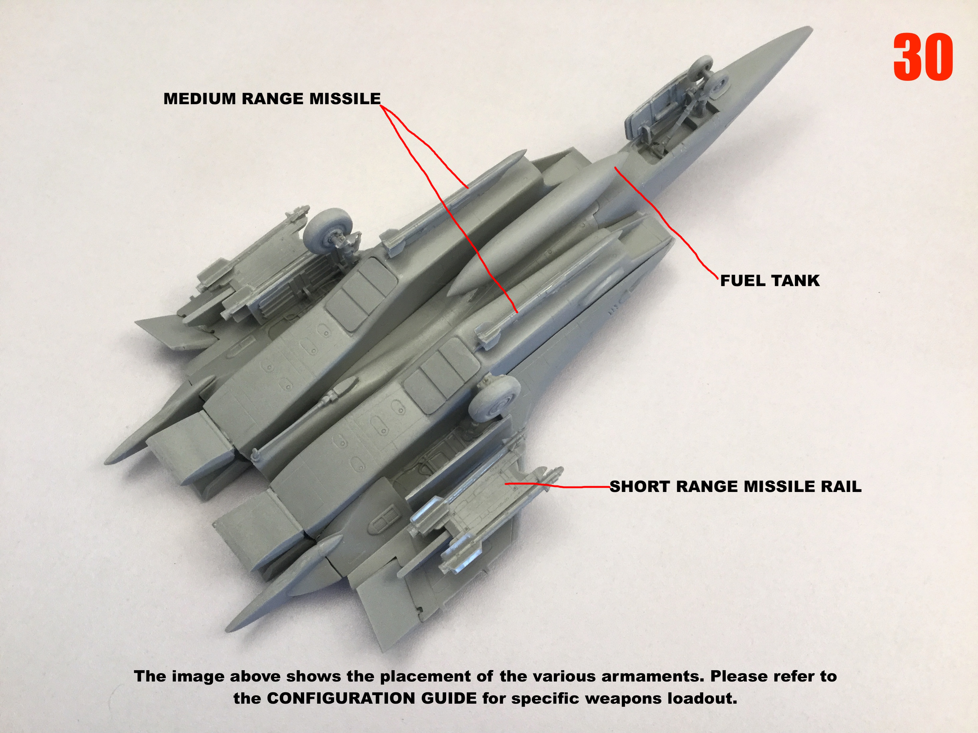
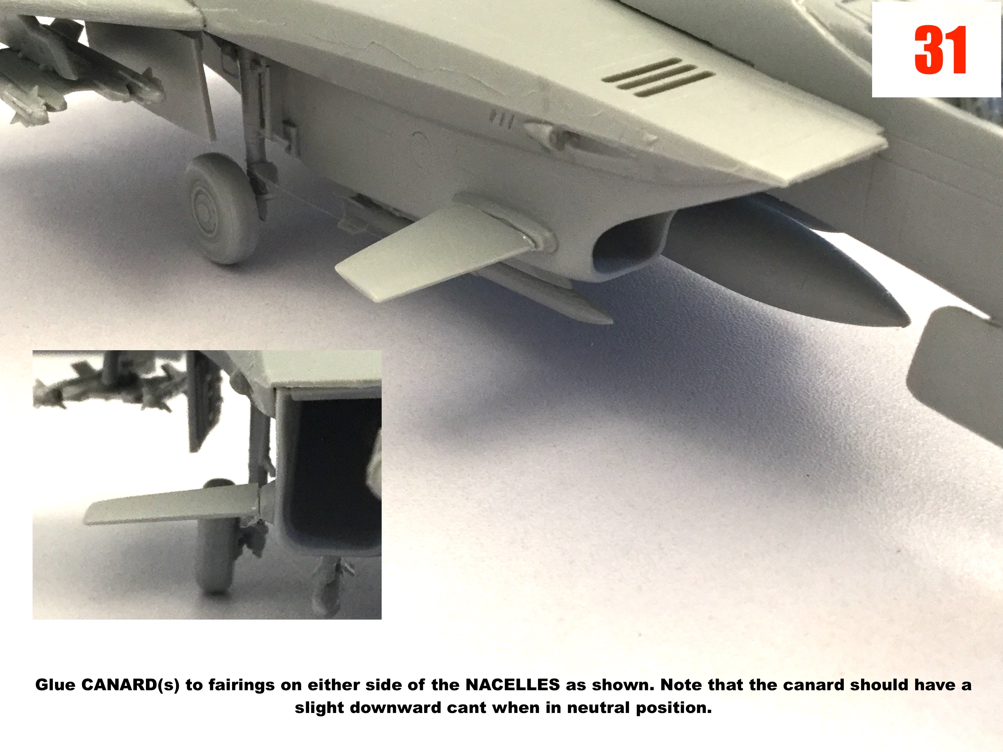
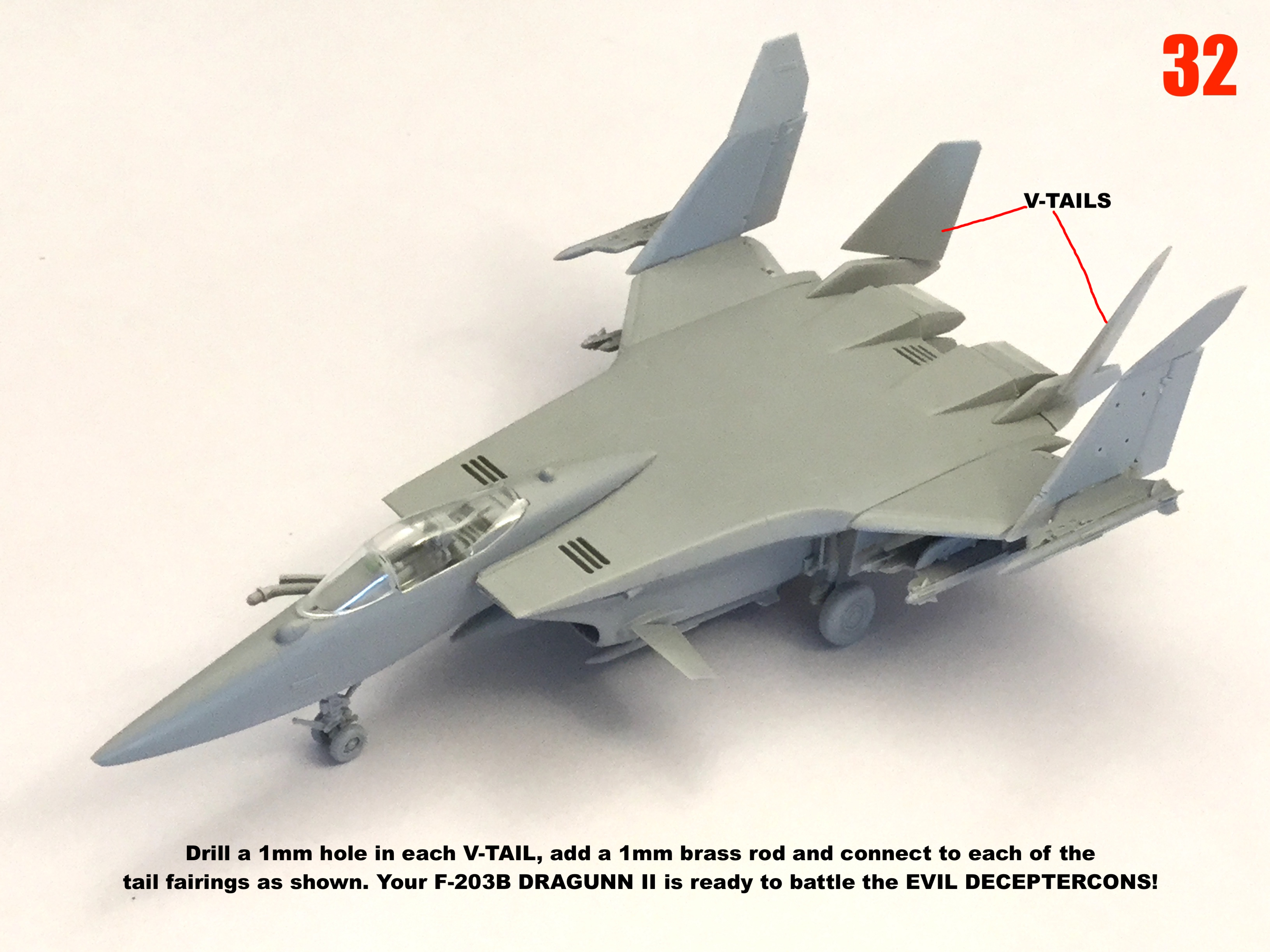
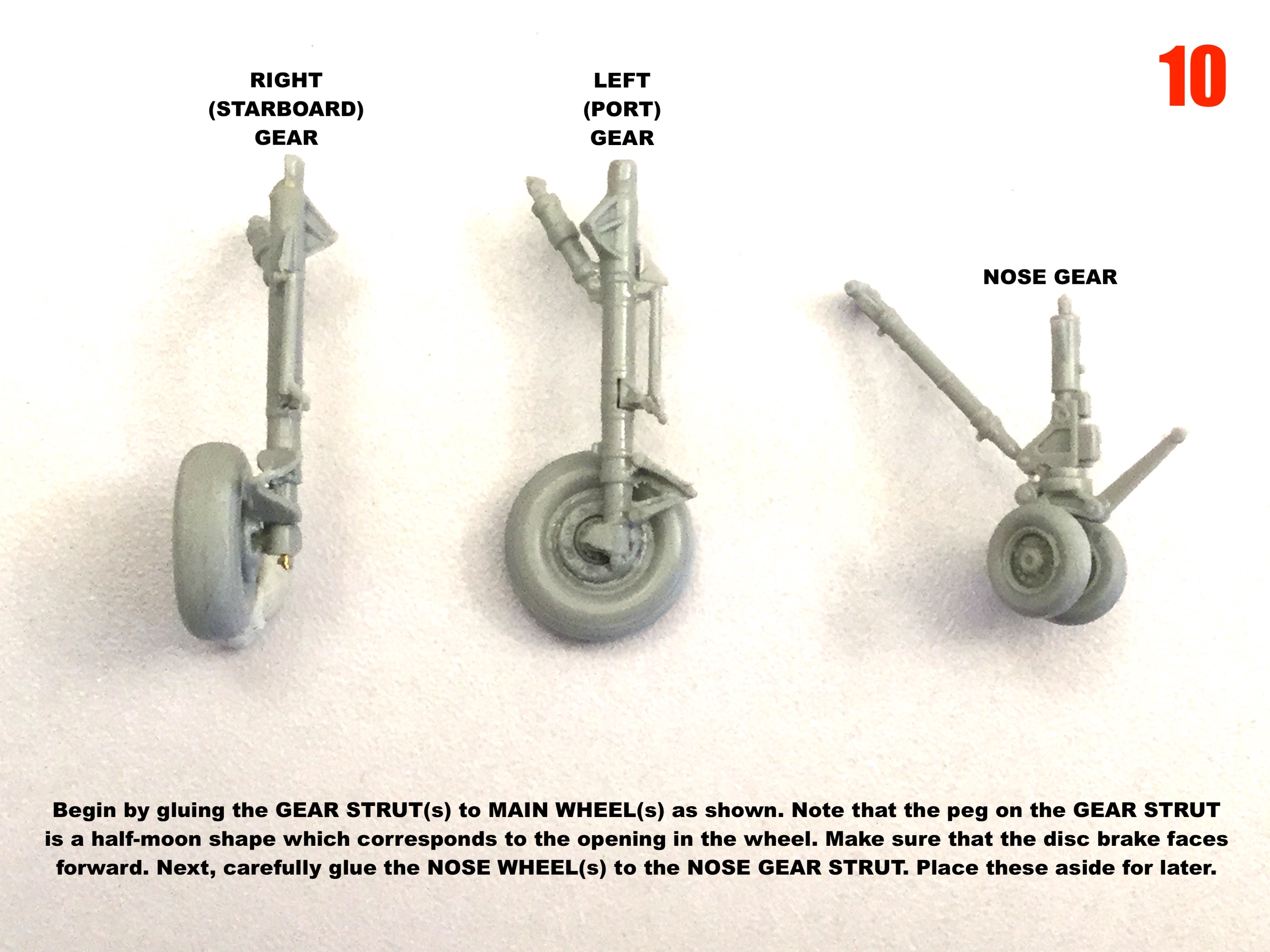
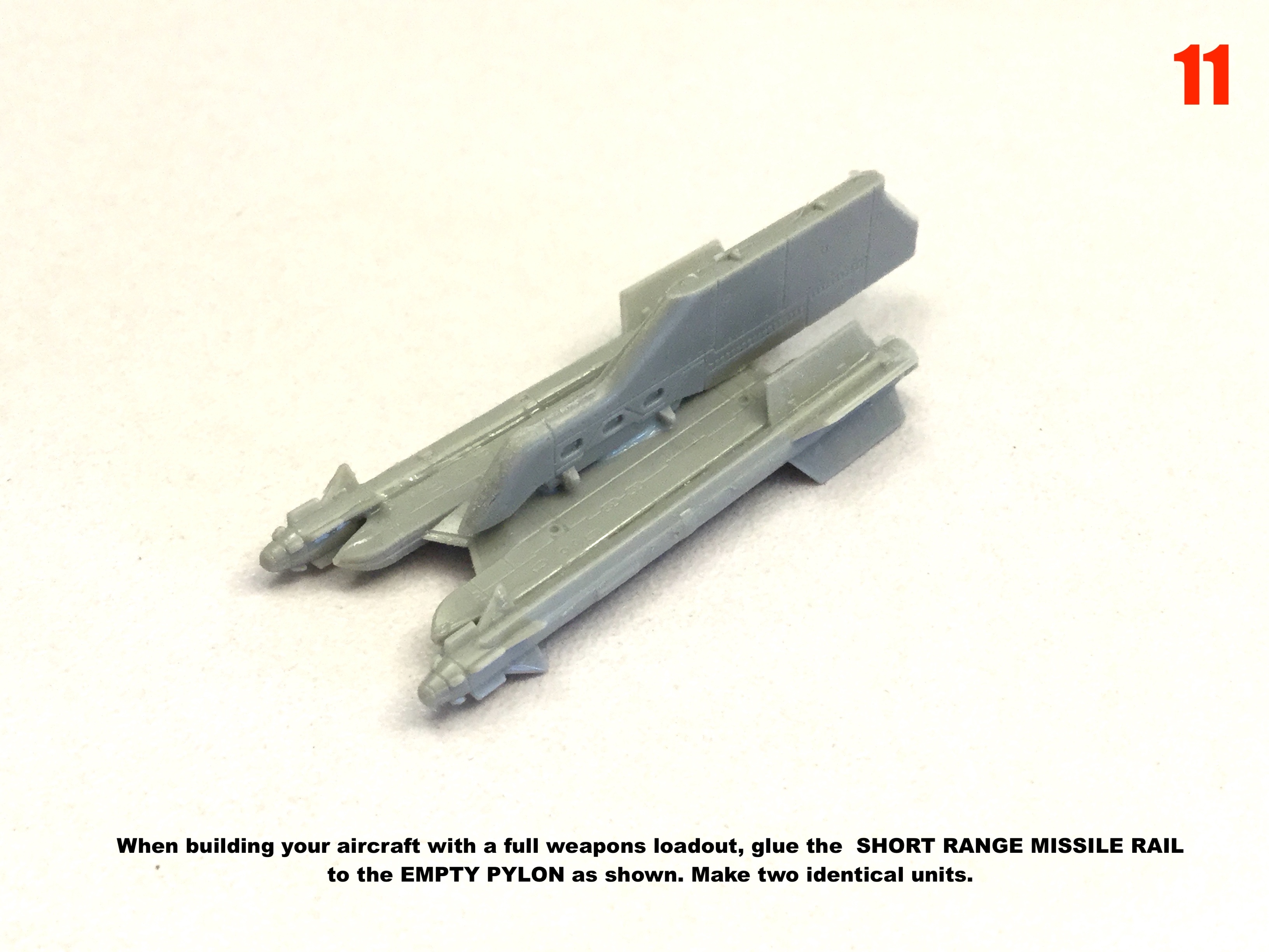
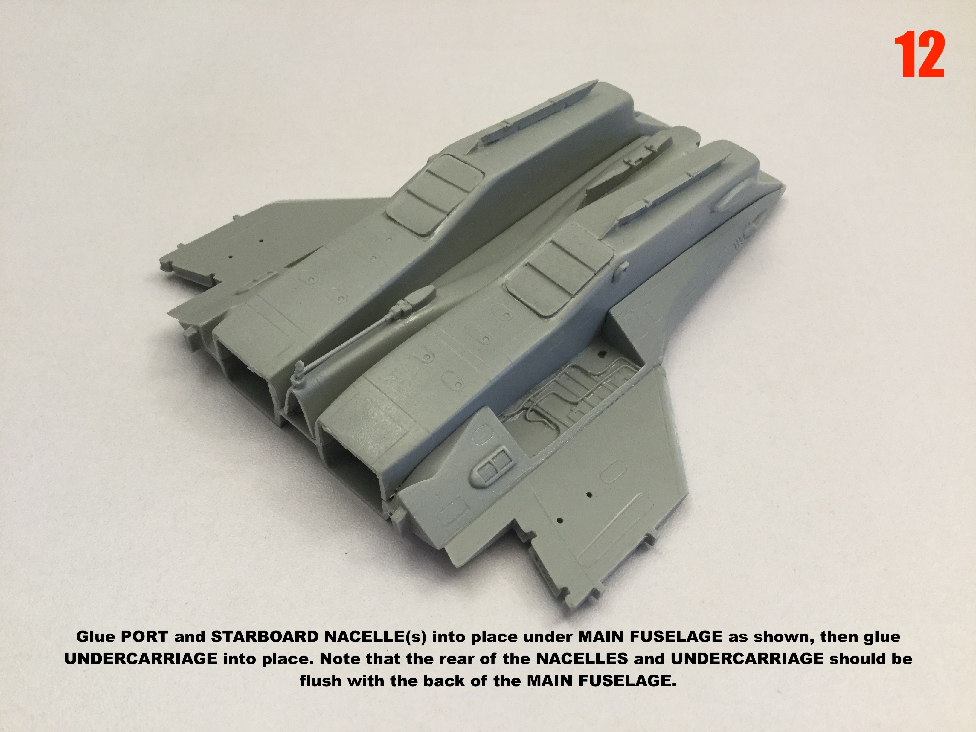
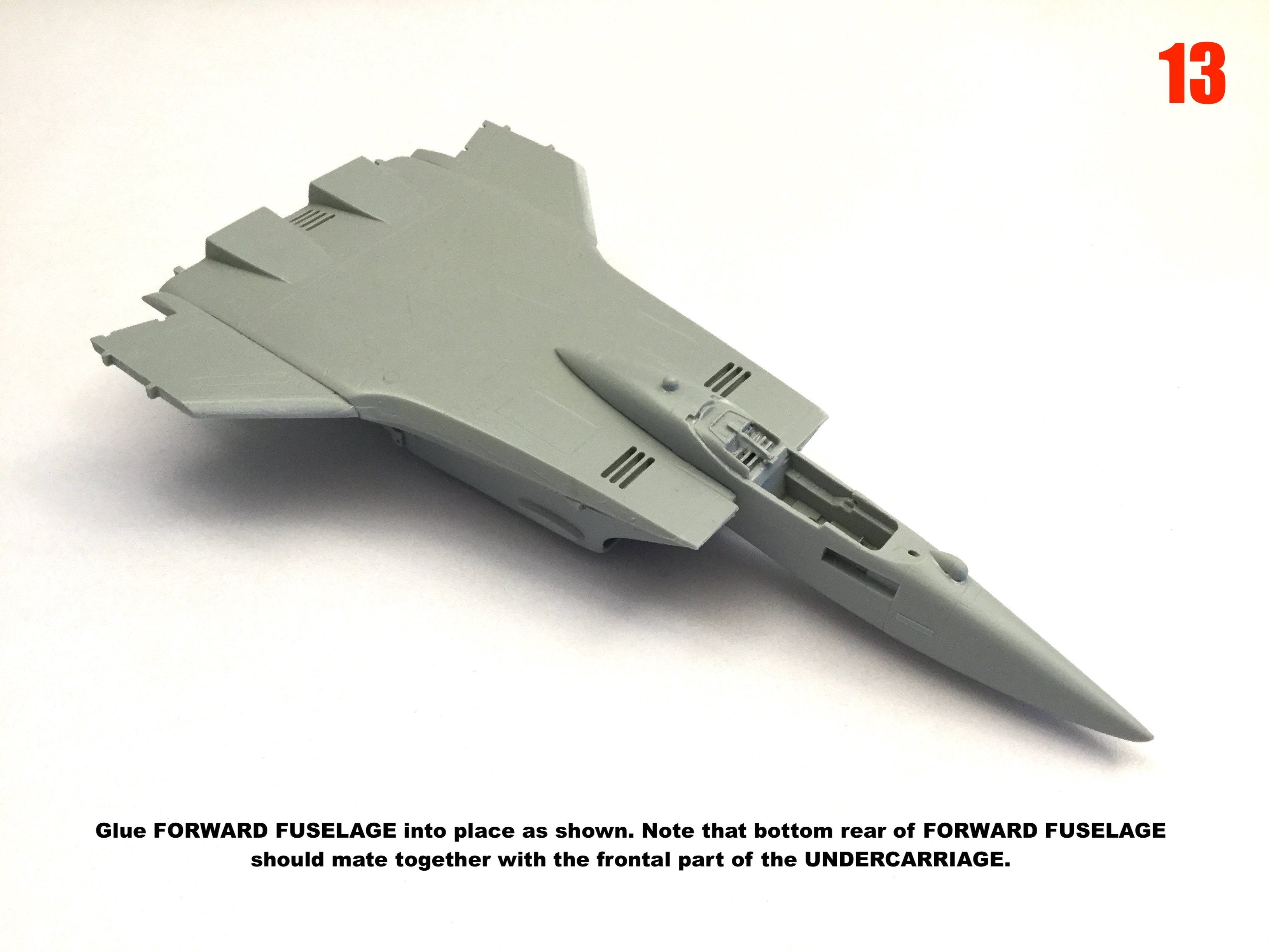
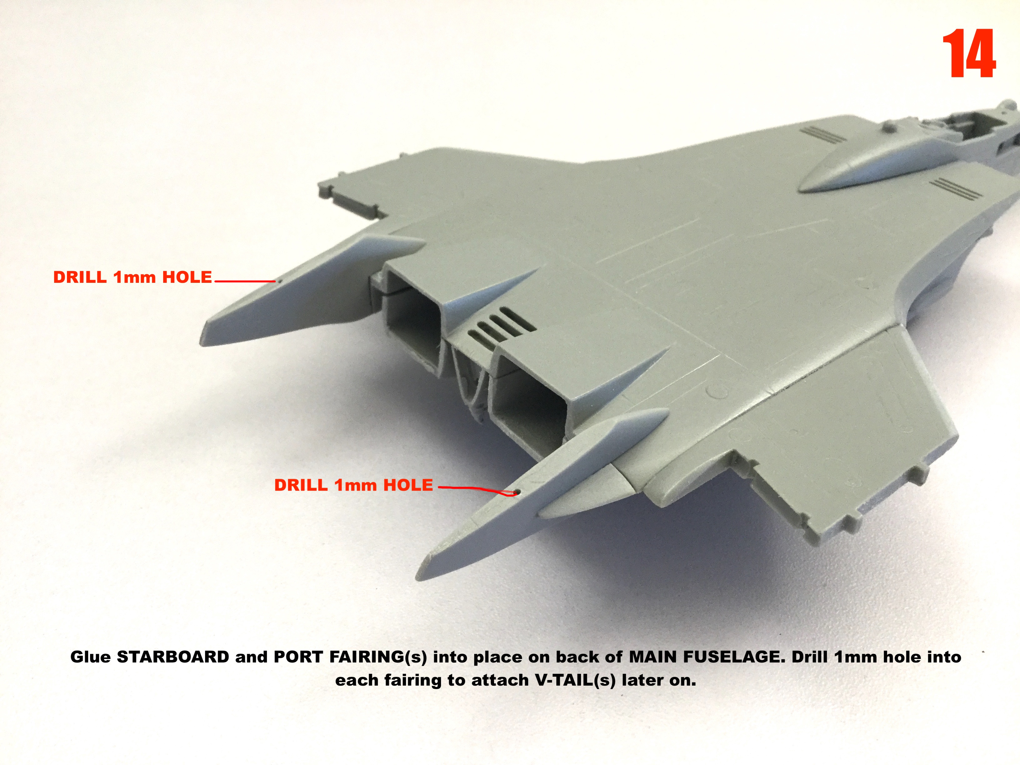
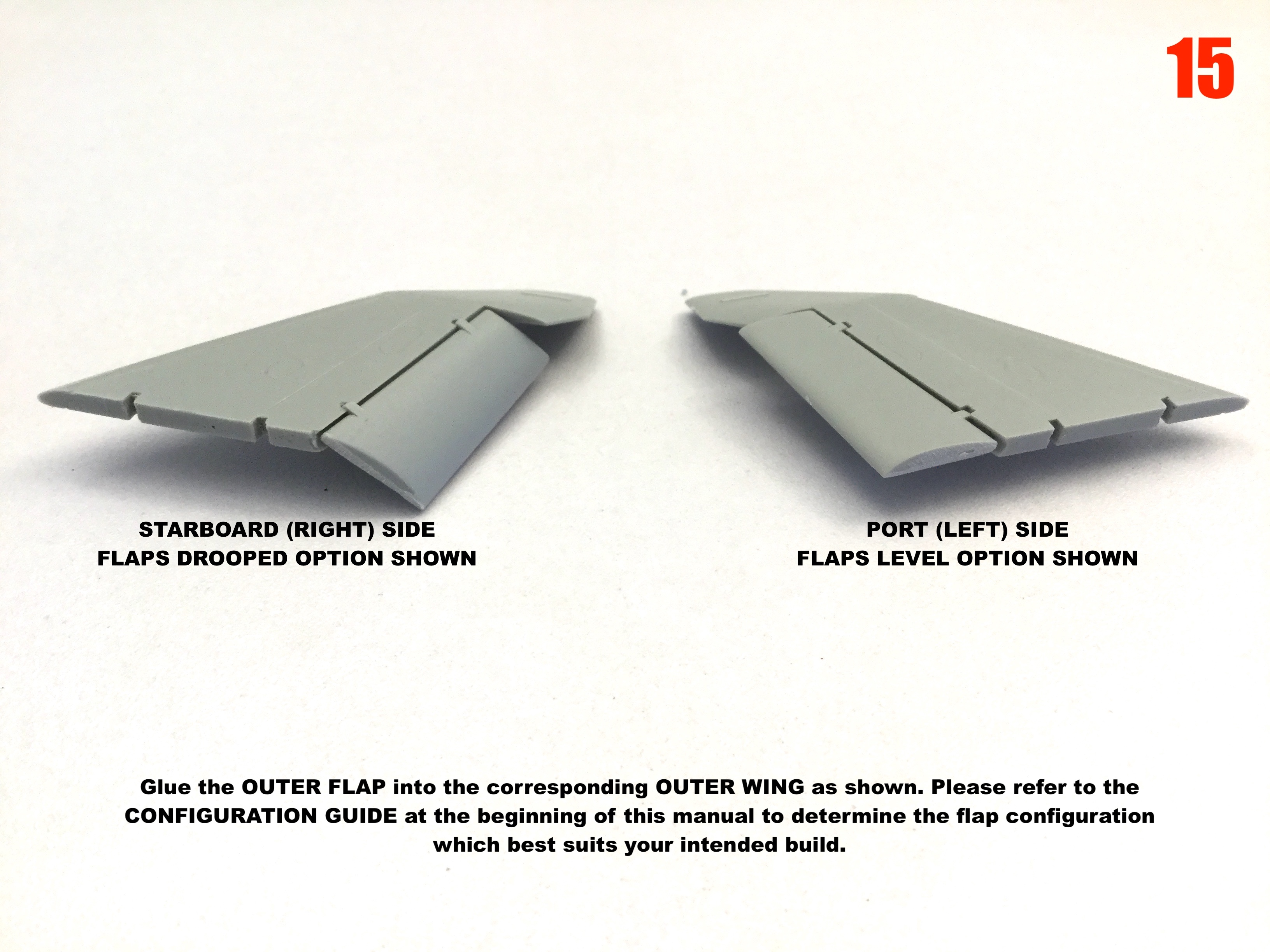
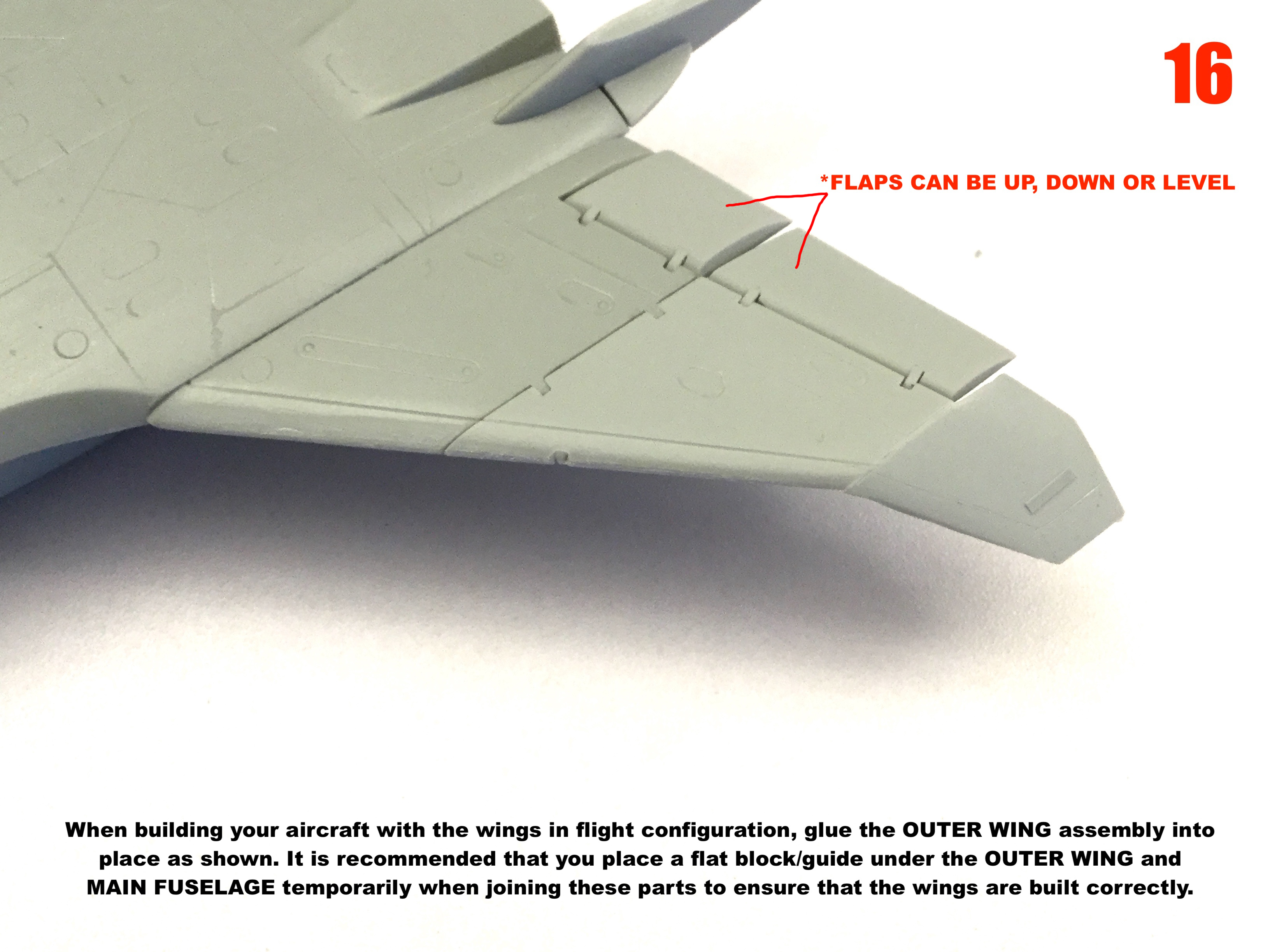
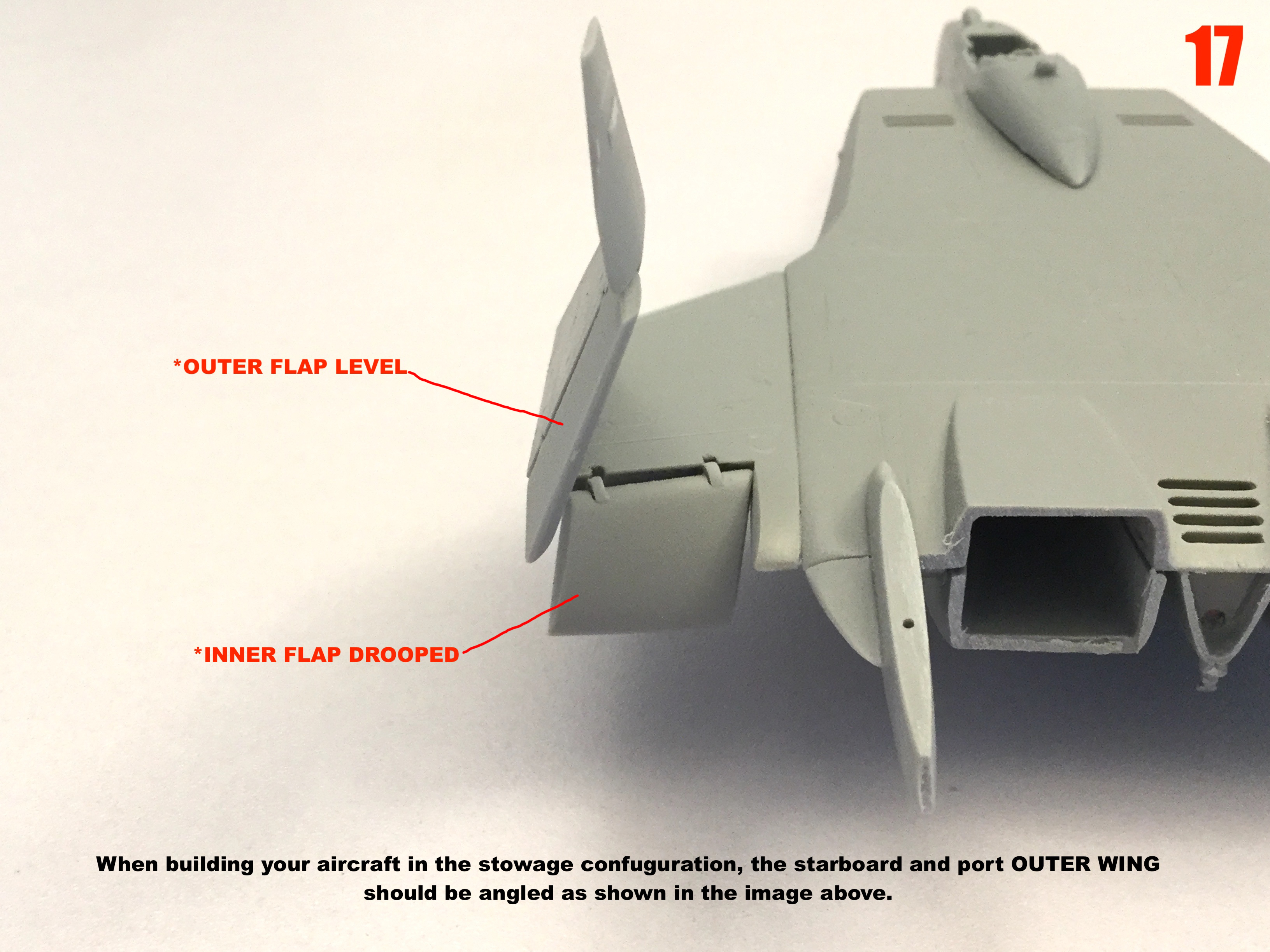
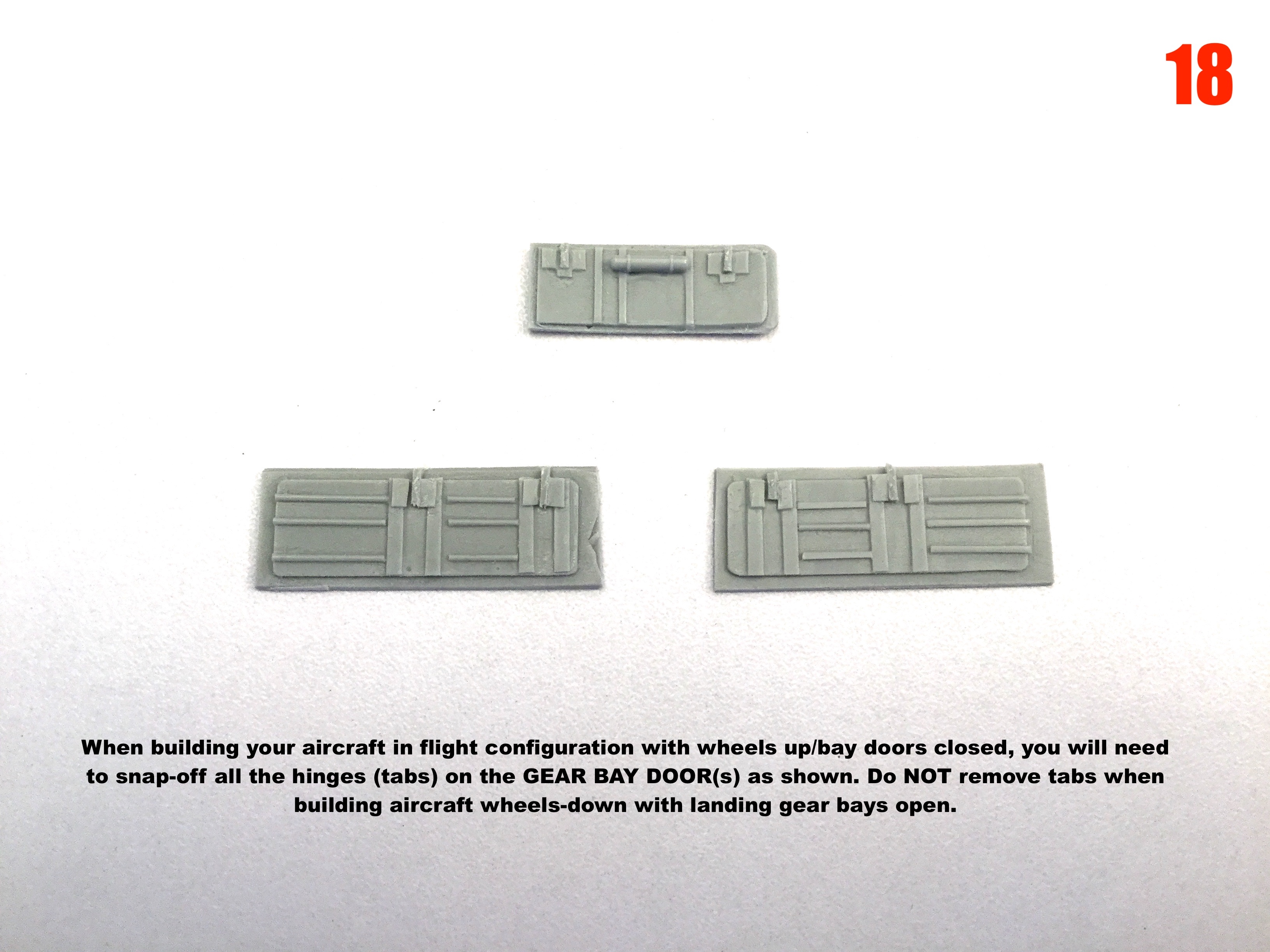
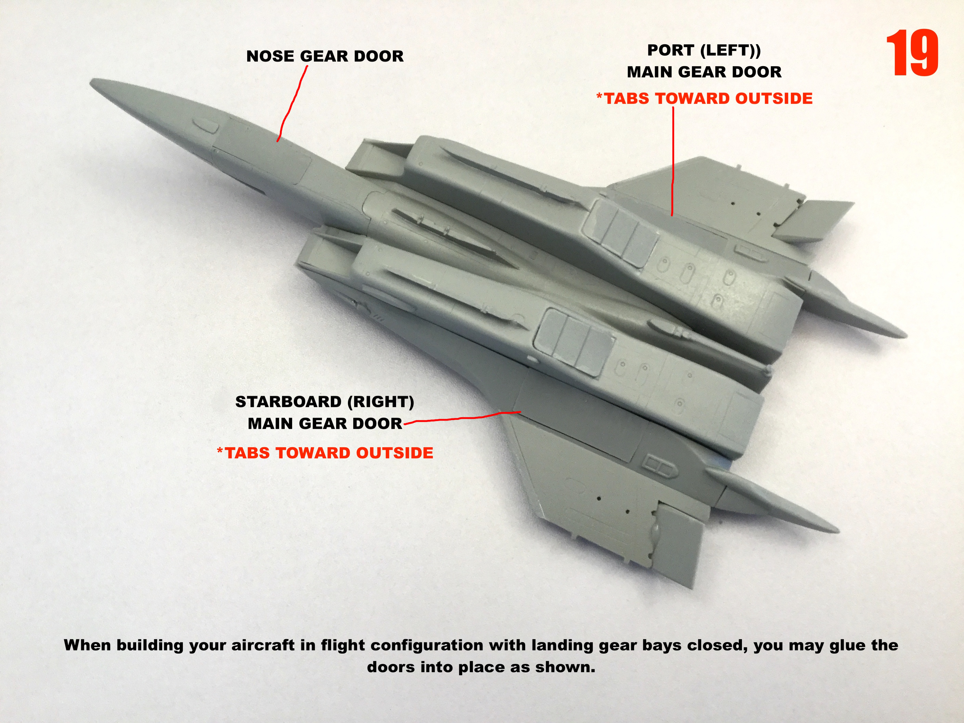
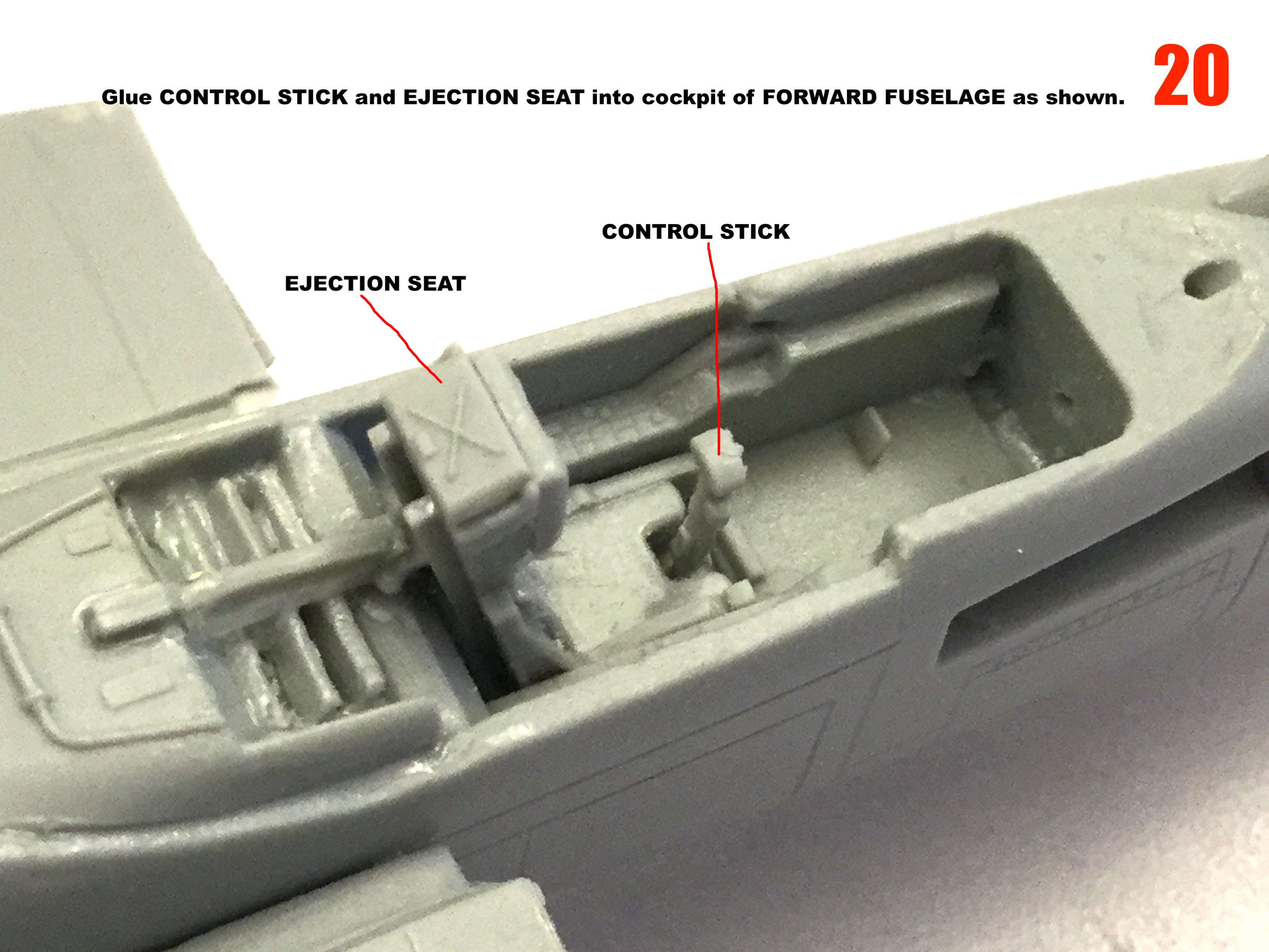
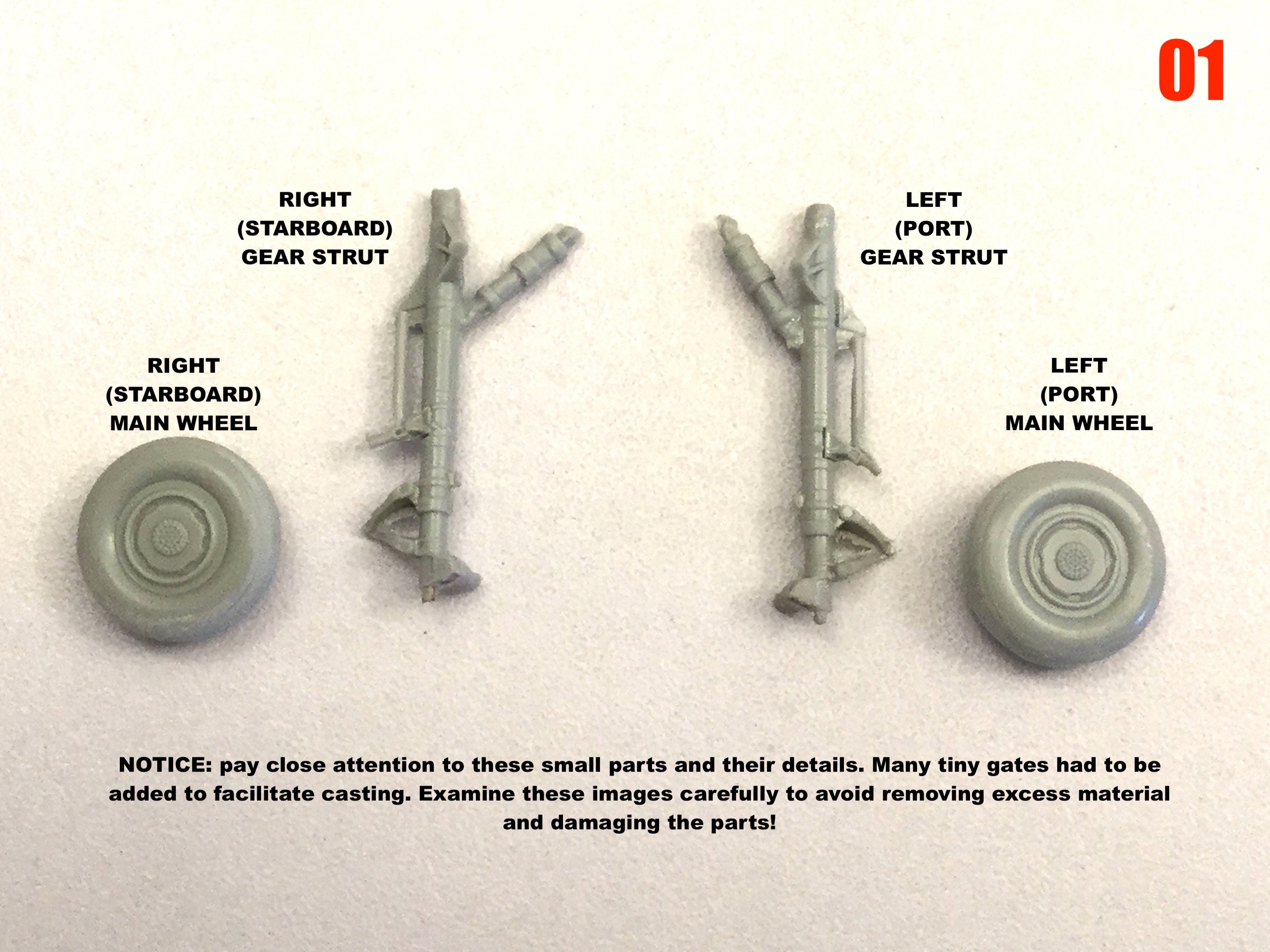
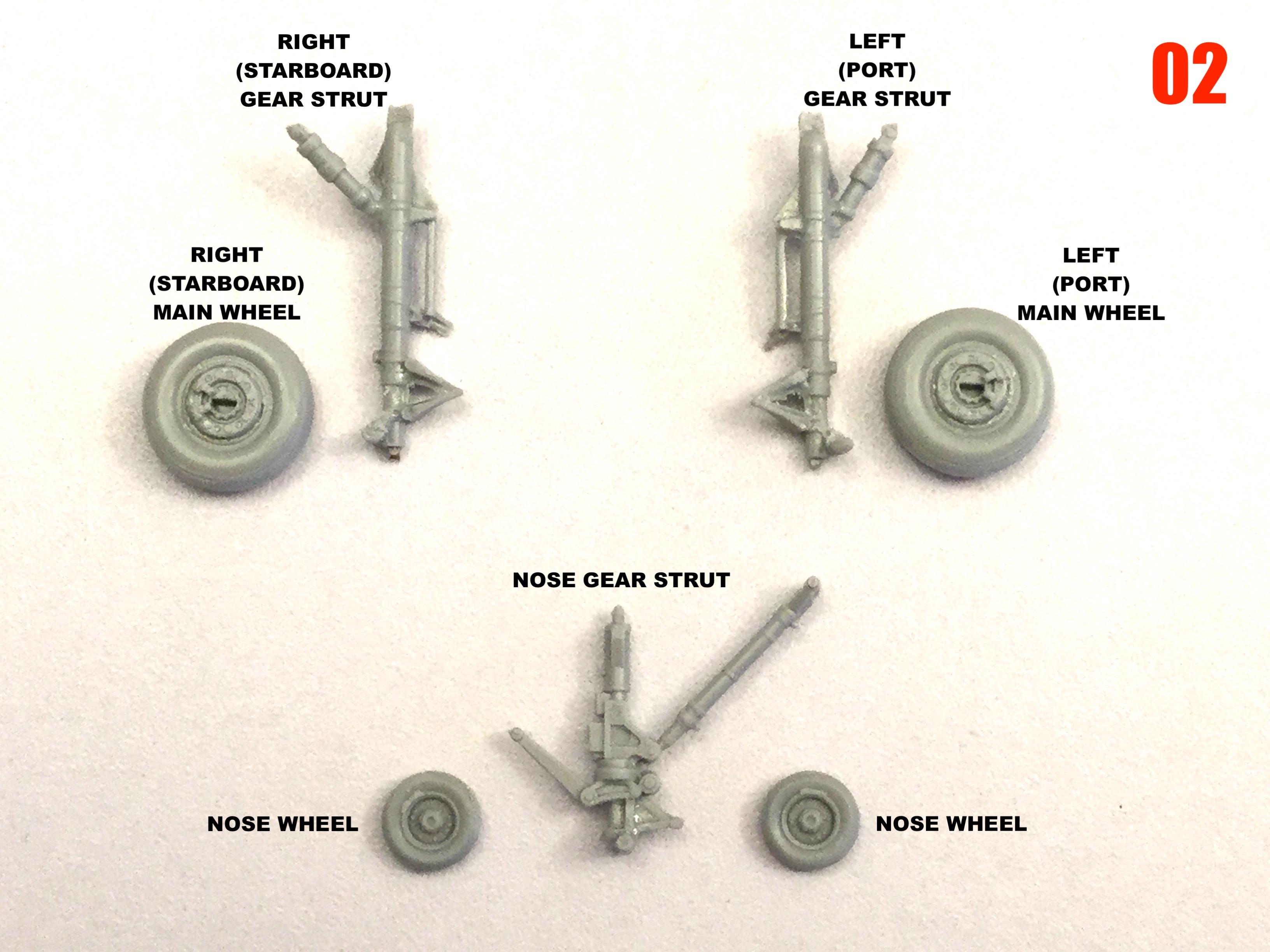
Instructions are done!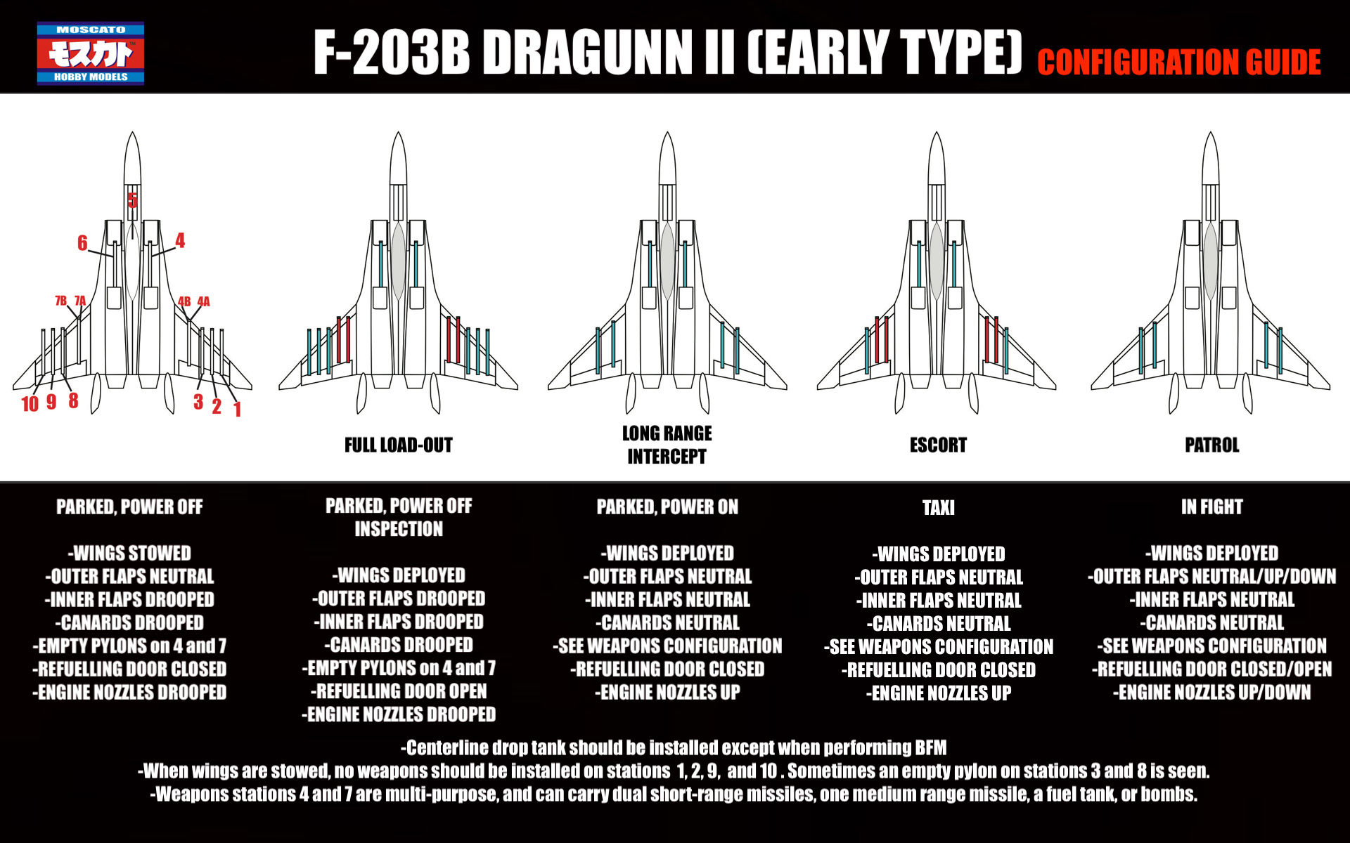

-
I did.
-
1/72 F203 Dragon II Kit Proposal --Moscato Hobby
captain america replied to captain america's topic in Model kits
All the kits went out in two batches: one on Friday, the other earlier today. Once it's in the hands of UPS, there's a myriad of factors that influence transit time. -
1/72 F203 Dragon II Kit Proposal --Moscato Hobby
captain america replied to captain america's topic in Model kits
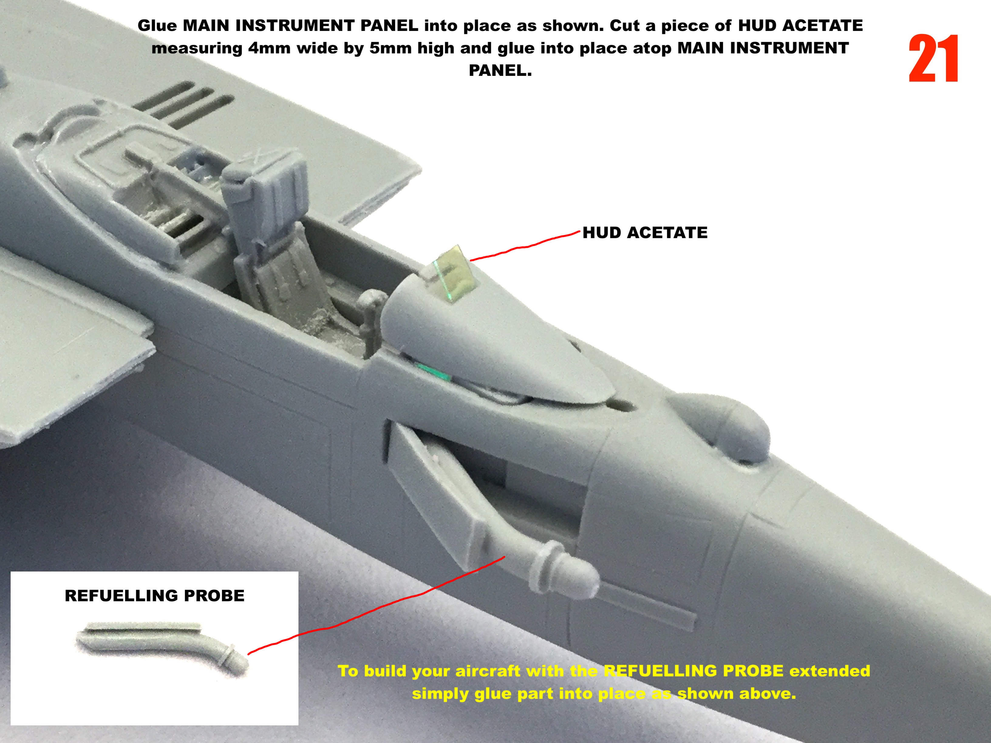
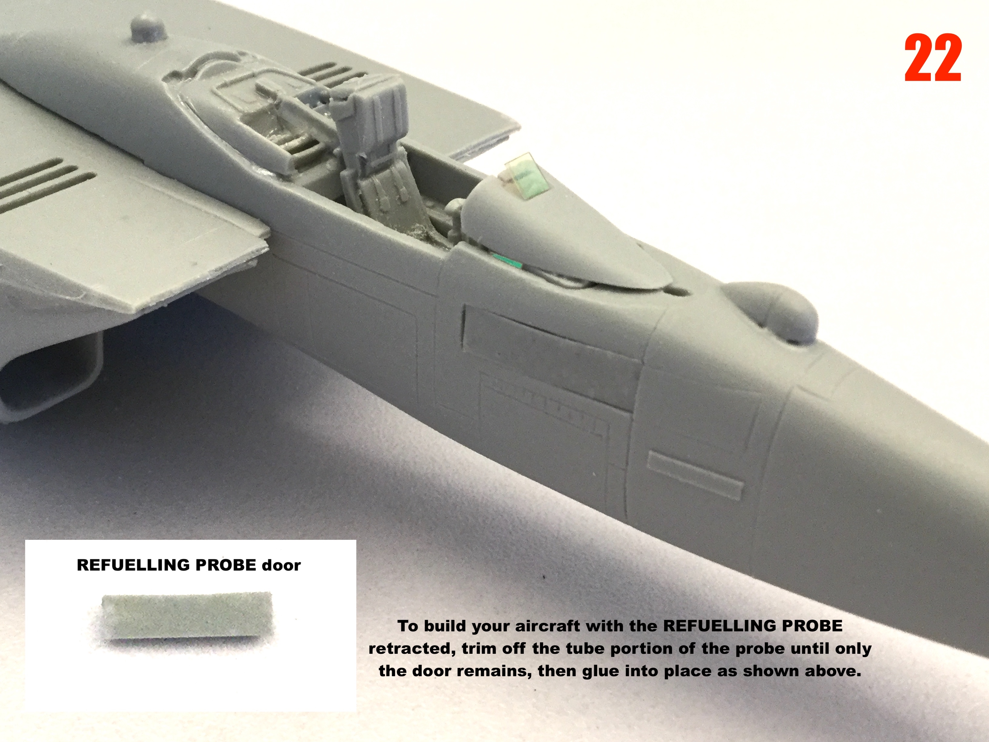
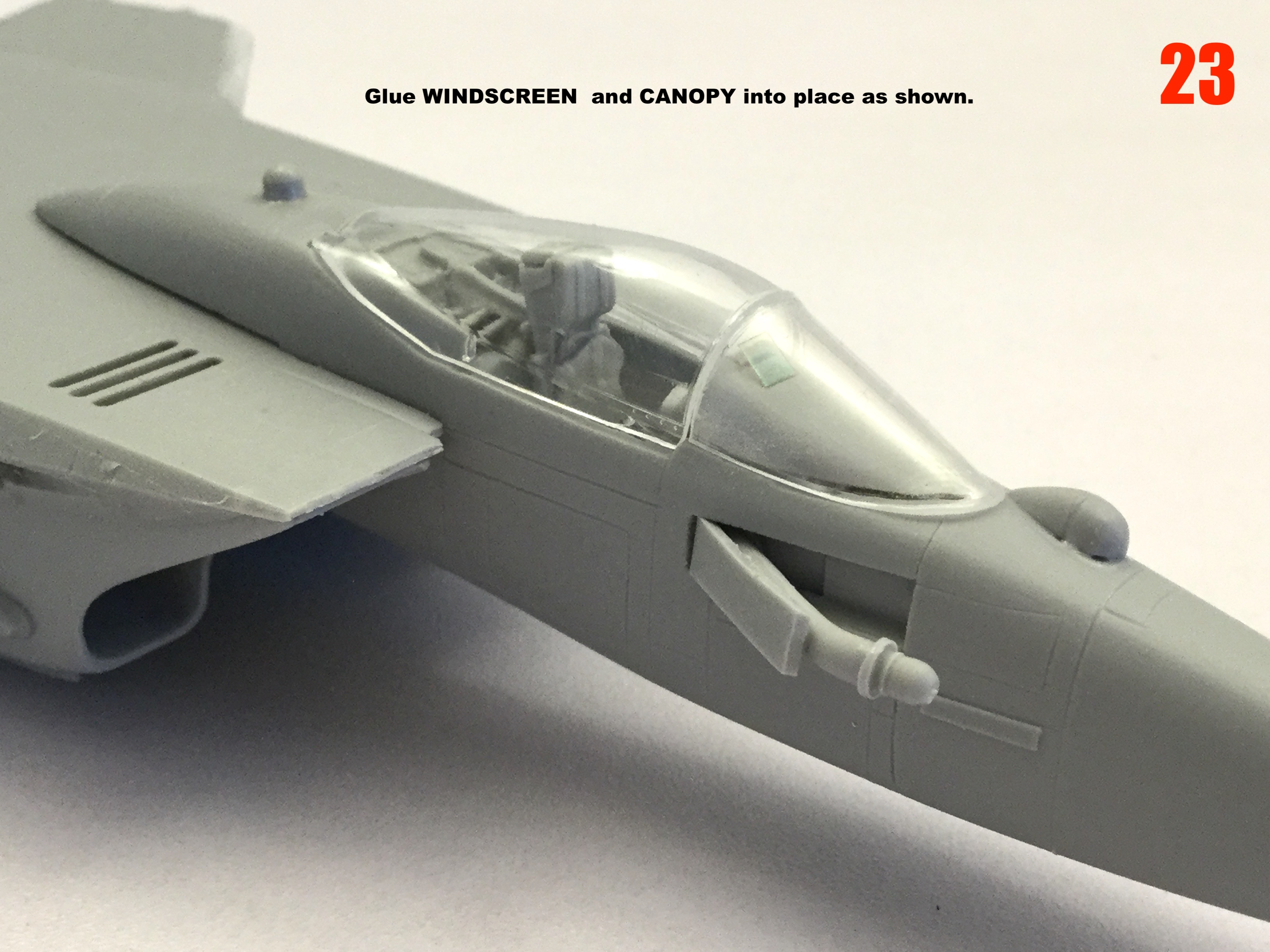
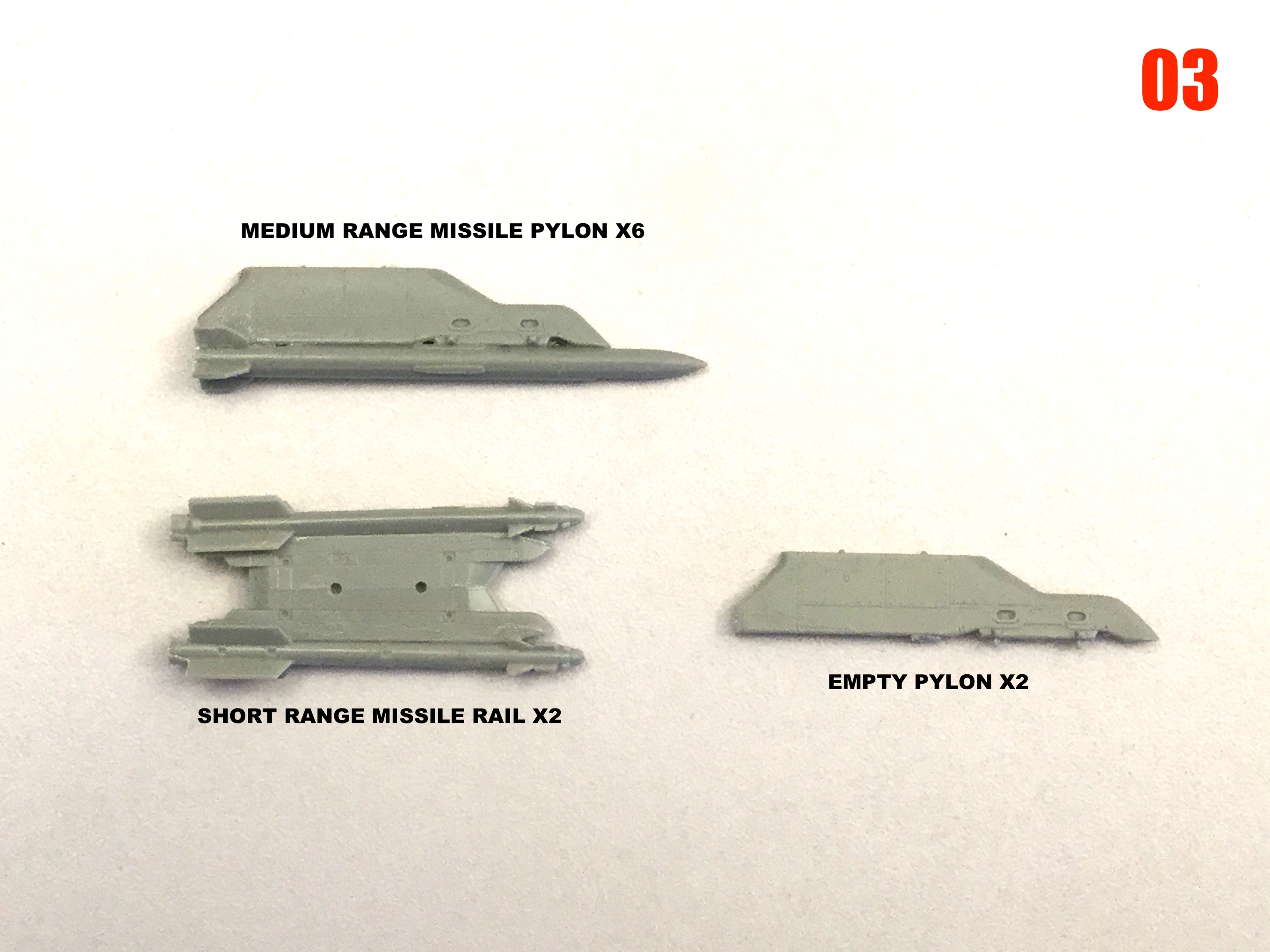
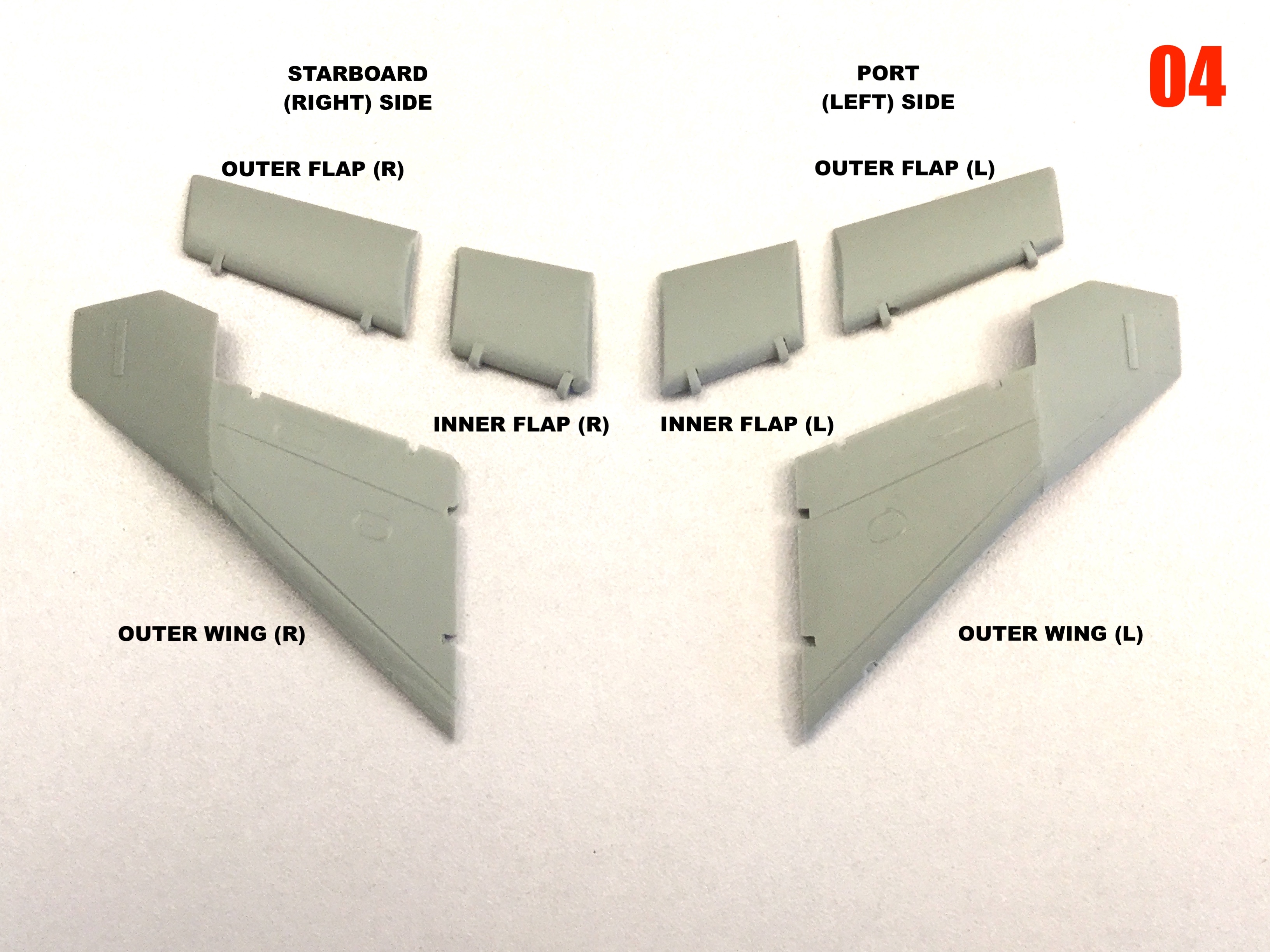
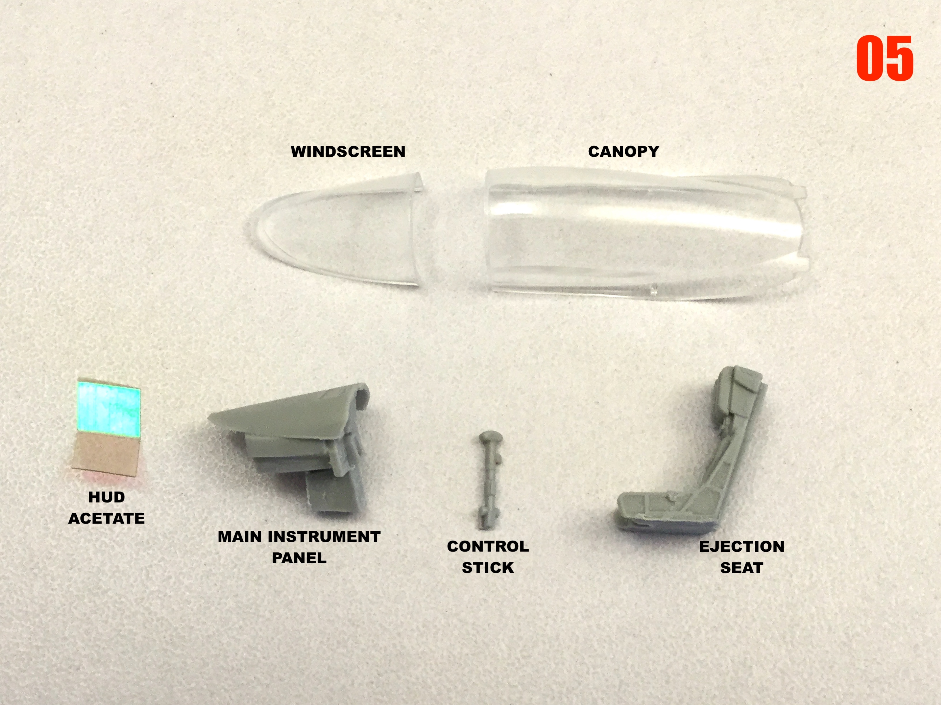
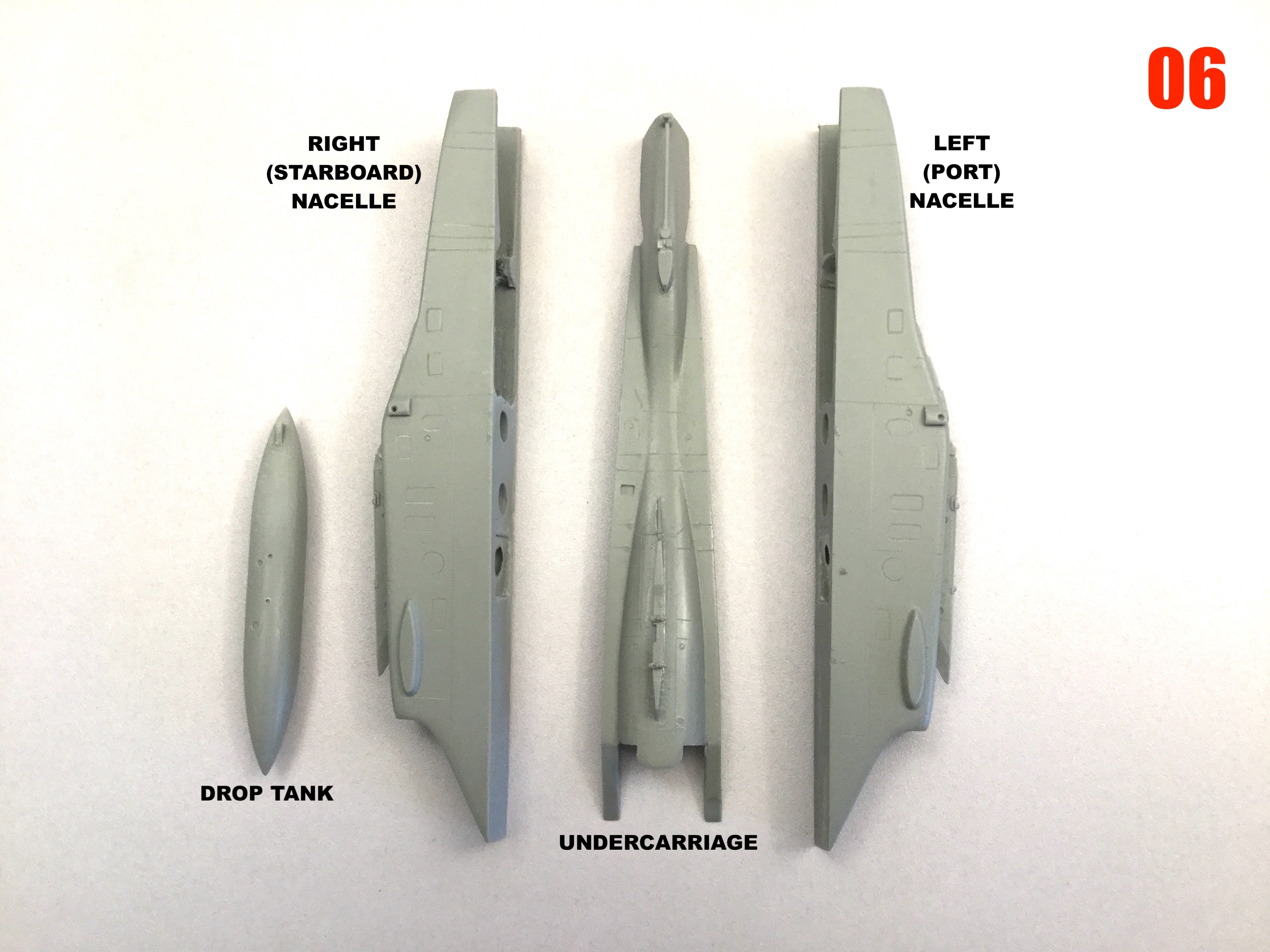
This is what's in the box. It's not shown, but I'm also including a small piece of metalized acetate to make the HUD from.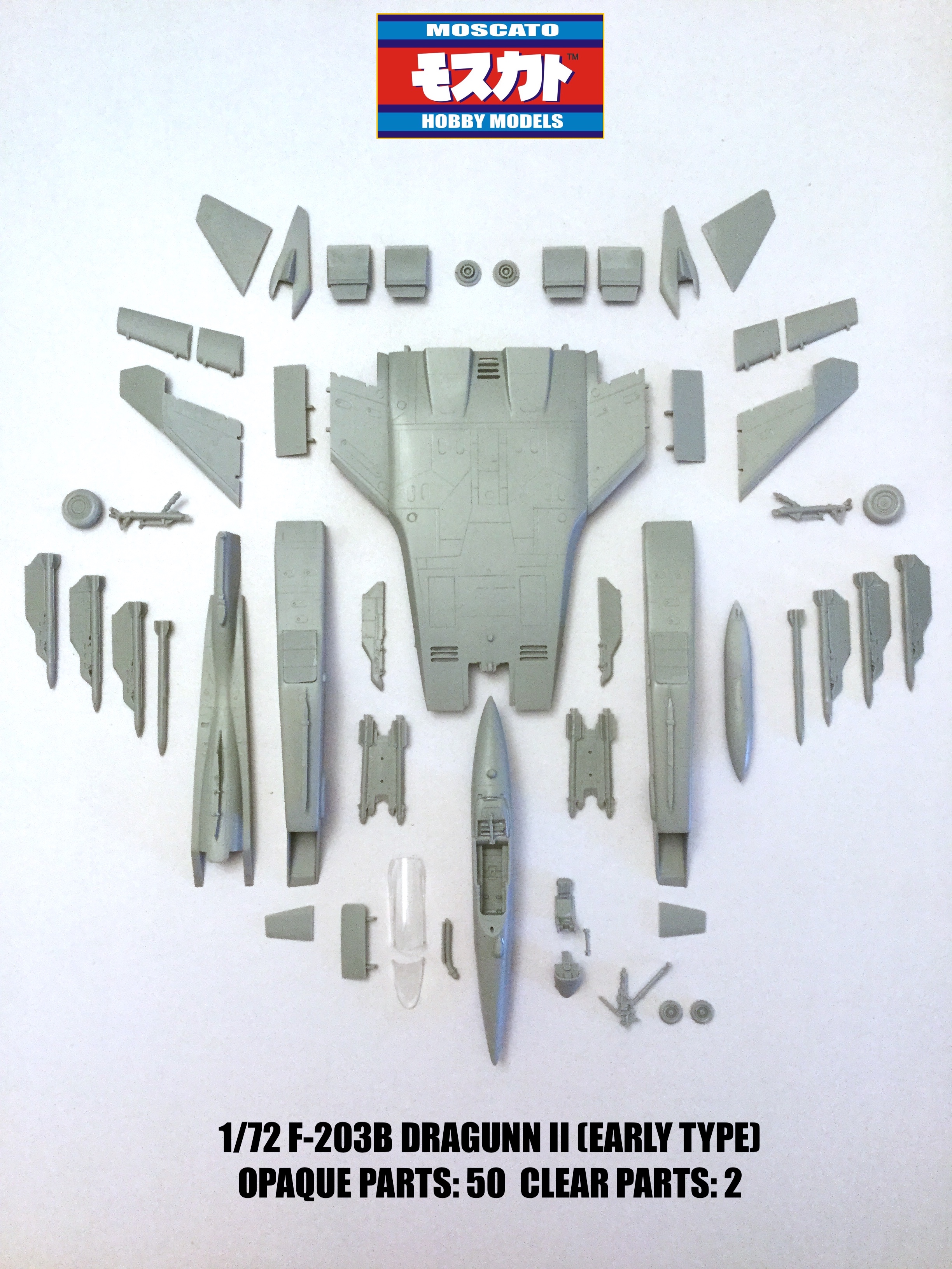
-
1/72 F203 Dragon II Kit Proposal --Moscato Hobby
captain america replied to captain america's topic in Model kits
Kits are being packed-up and should start shipping on Monday. Jose Jauregui: please PM me!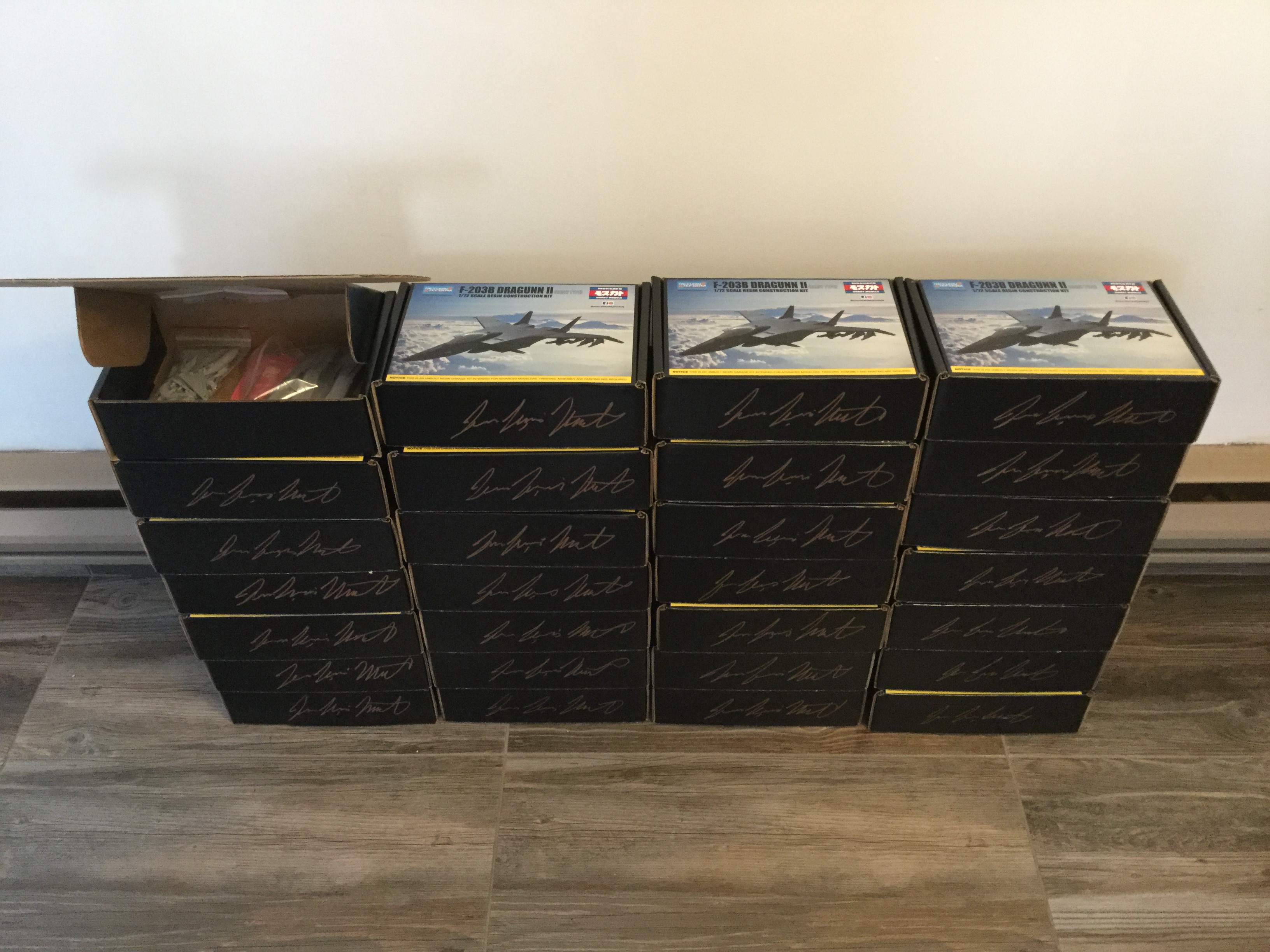
-
1/72 F203 Dragon II Kit Proposal --Moscato Hobby
captain america replied to captain america's topic in Model kits
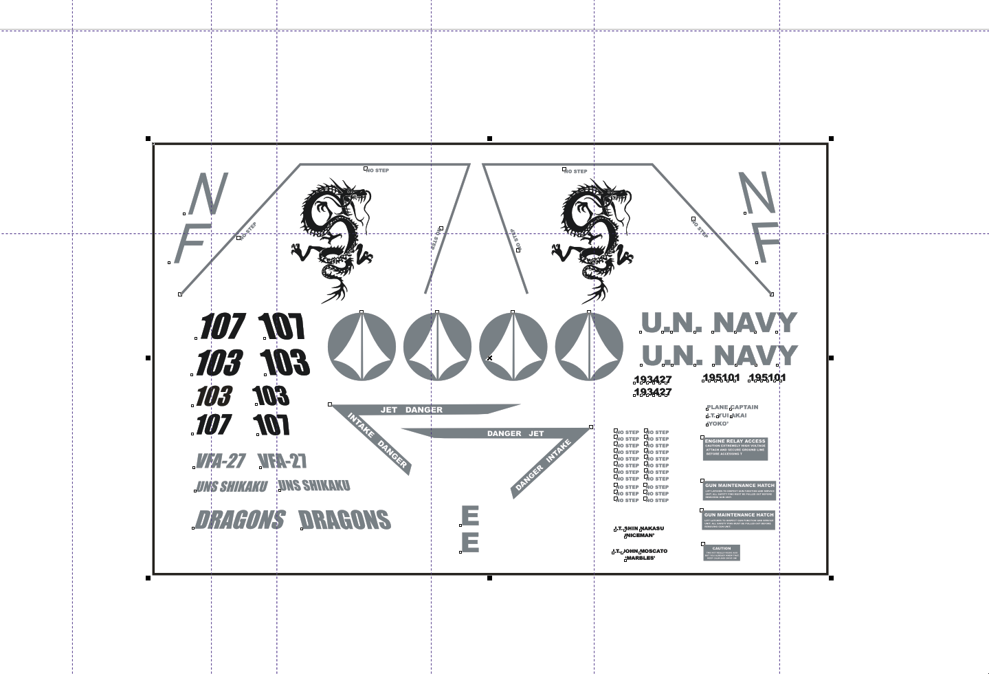
Decal placement guide and decal layout finalized. f203 dragunn decals artwork.ai f203 dragunn decals artwork.cdr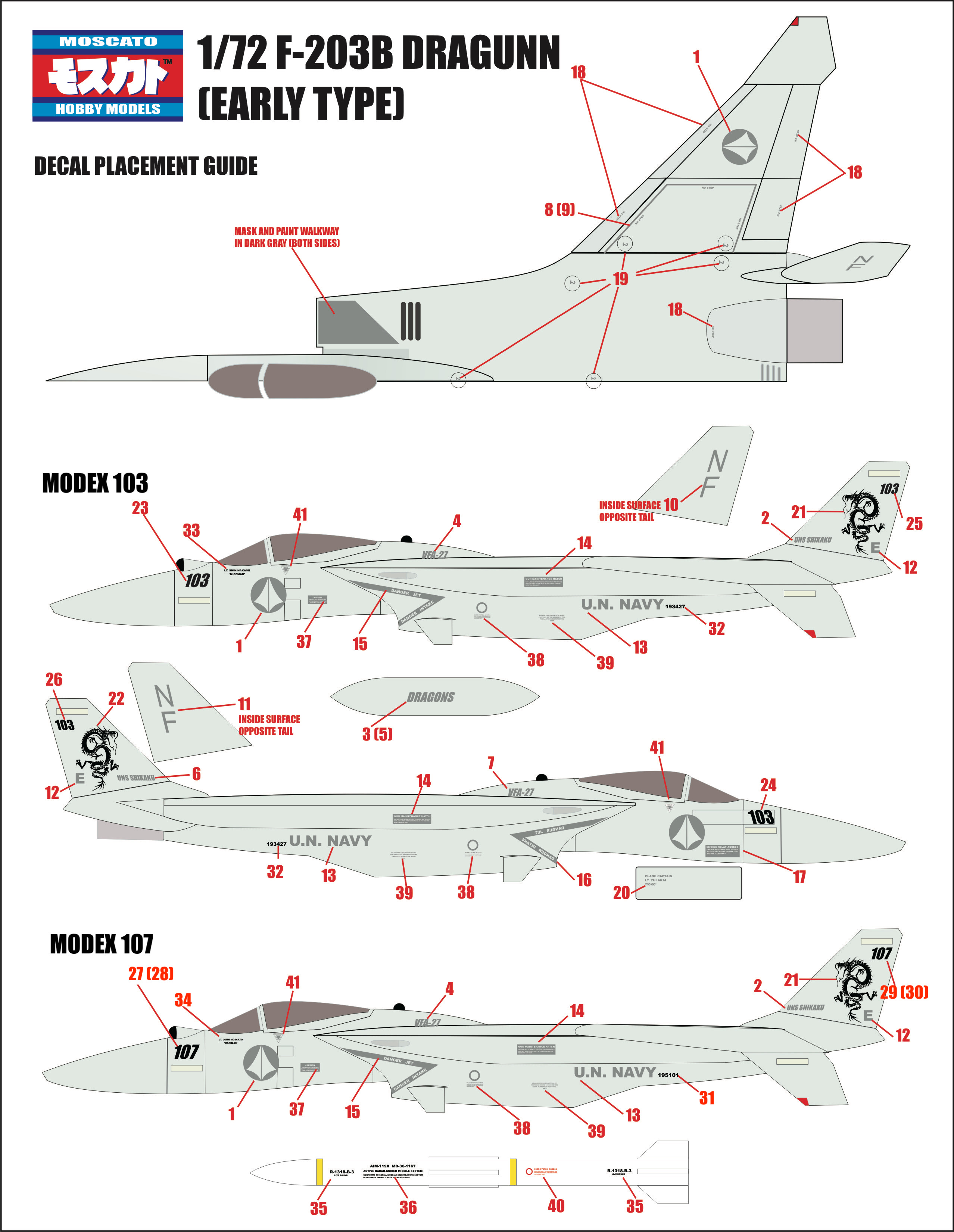
-
Now that's a beautiful Norbert-Gerard!
-
1/72 F203 Dragon II Kit Proposal --Moscato Hobby
captain america replied to captain america's topic in Model kits
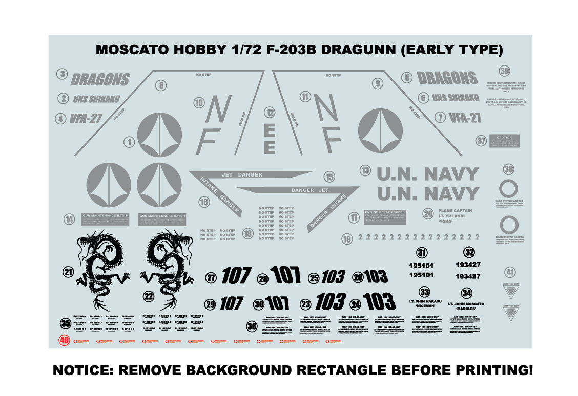
Hi guys. Just wanted to check-in and say that my silence of late has not been in vain. I'm currently at mid-point in the production run and things are going beautifully! I should be done with the bulk of the casting by the end of next week, and will dedicate myself to the decal artwork and then the kits will ship. If someone could suggest a way to host the decal files for people to download, I'd really appreciate it. They're really simple, 2 colors only (grey + black) for the low-viz scheme.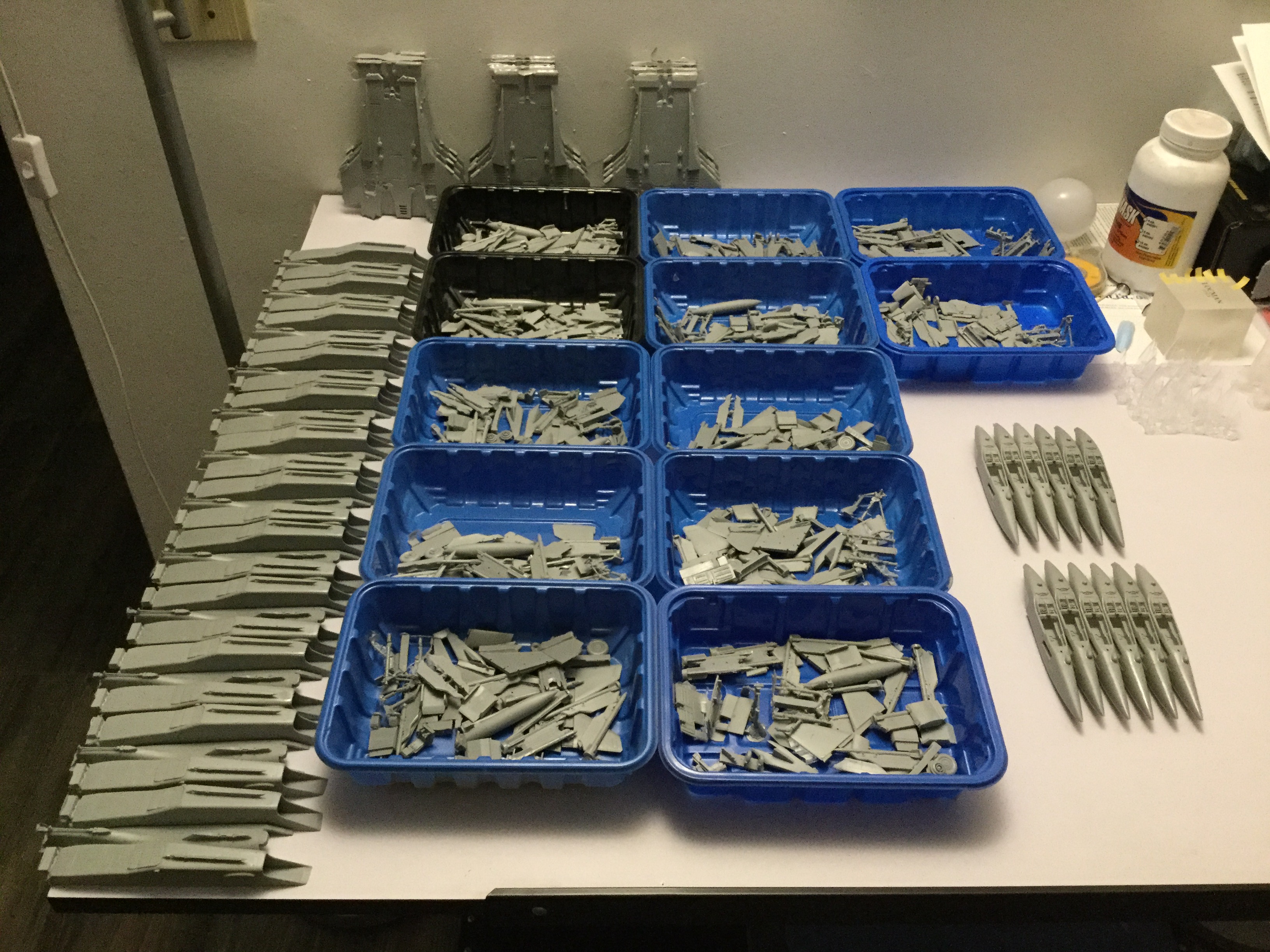
-
1/72 F203 Dragon II Kit Proposal --Moscato Hobby
captain america replied to captain america's topic in Model kits
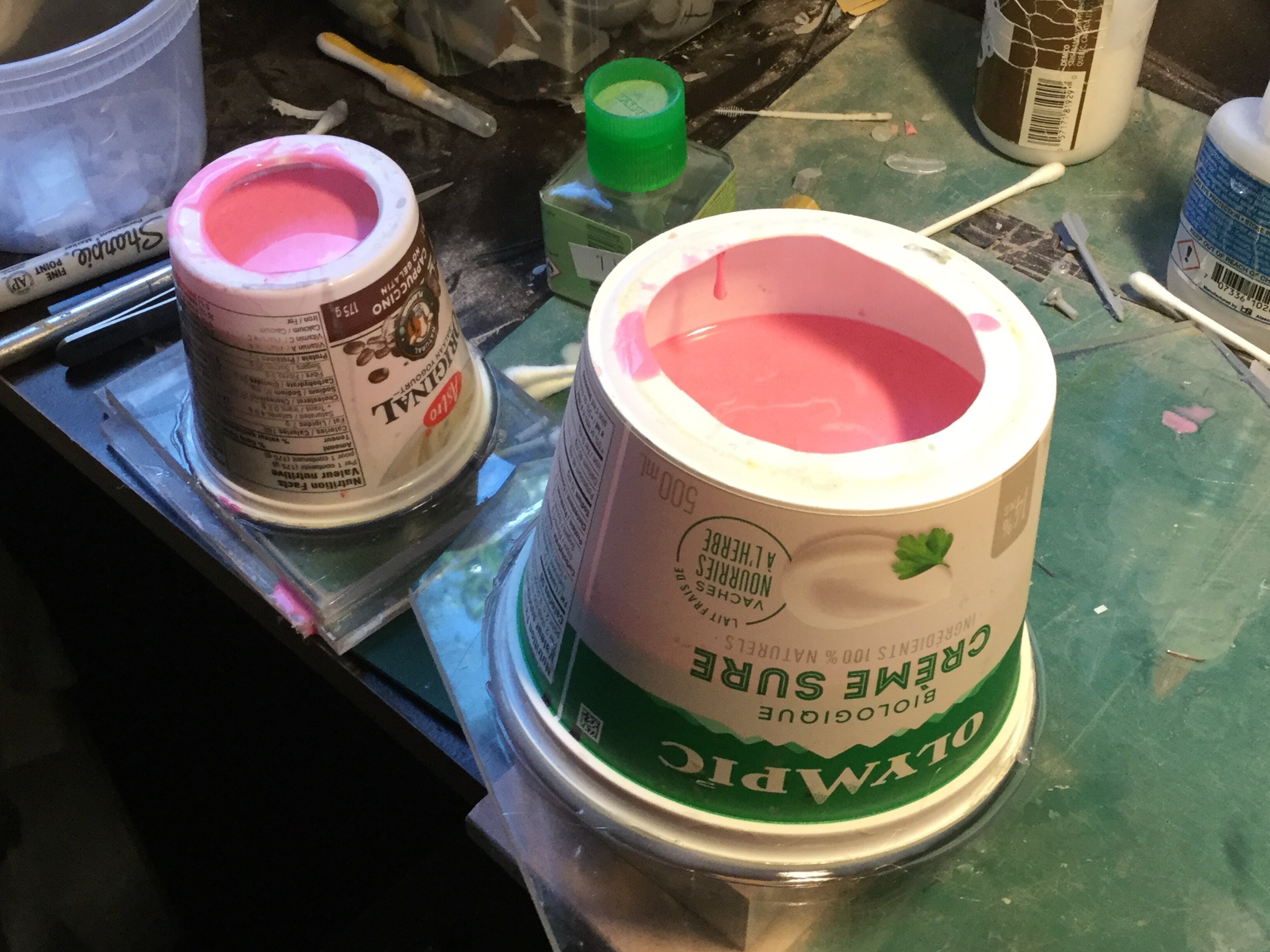
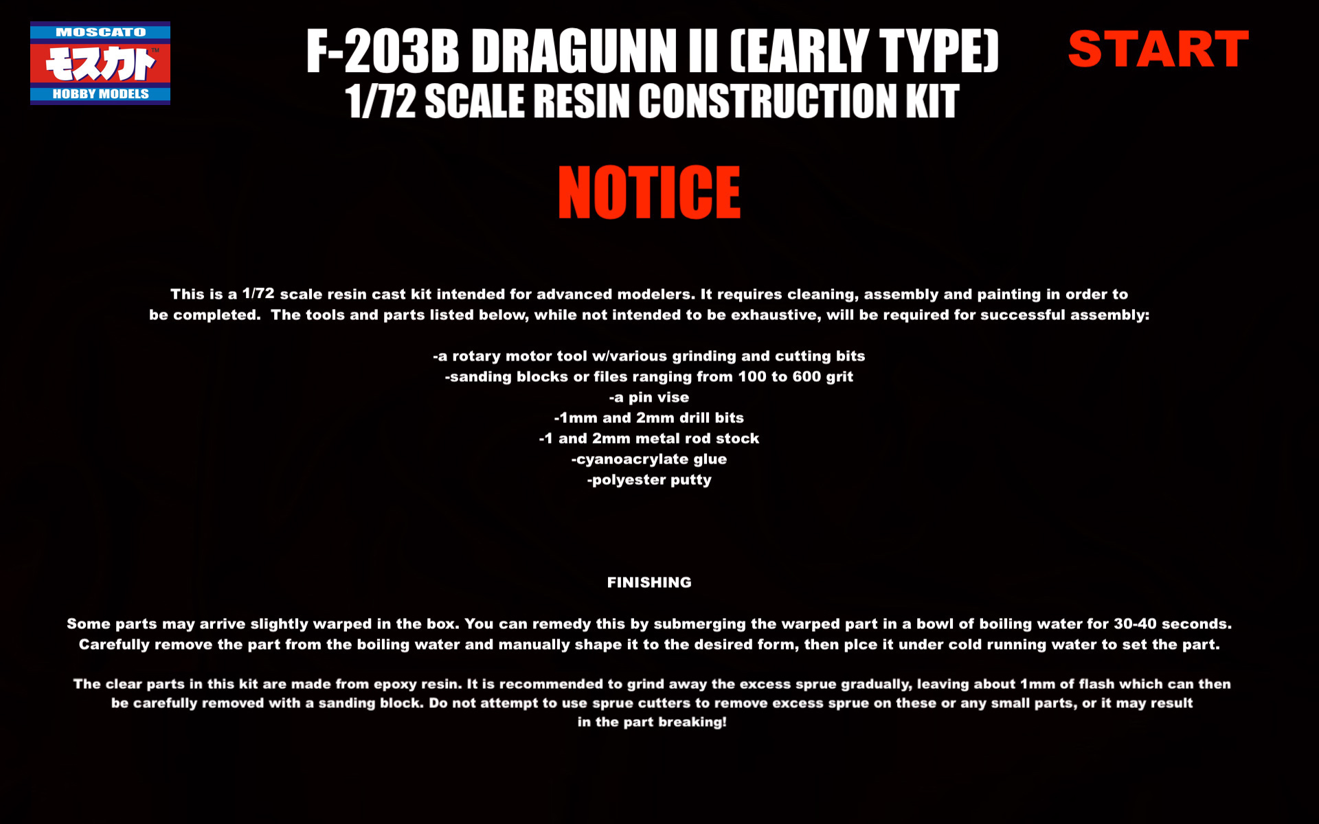
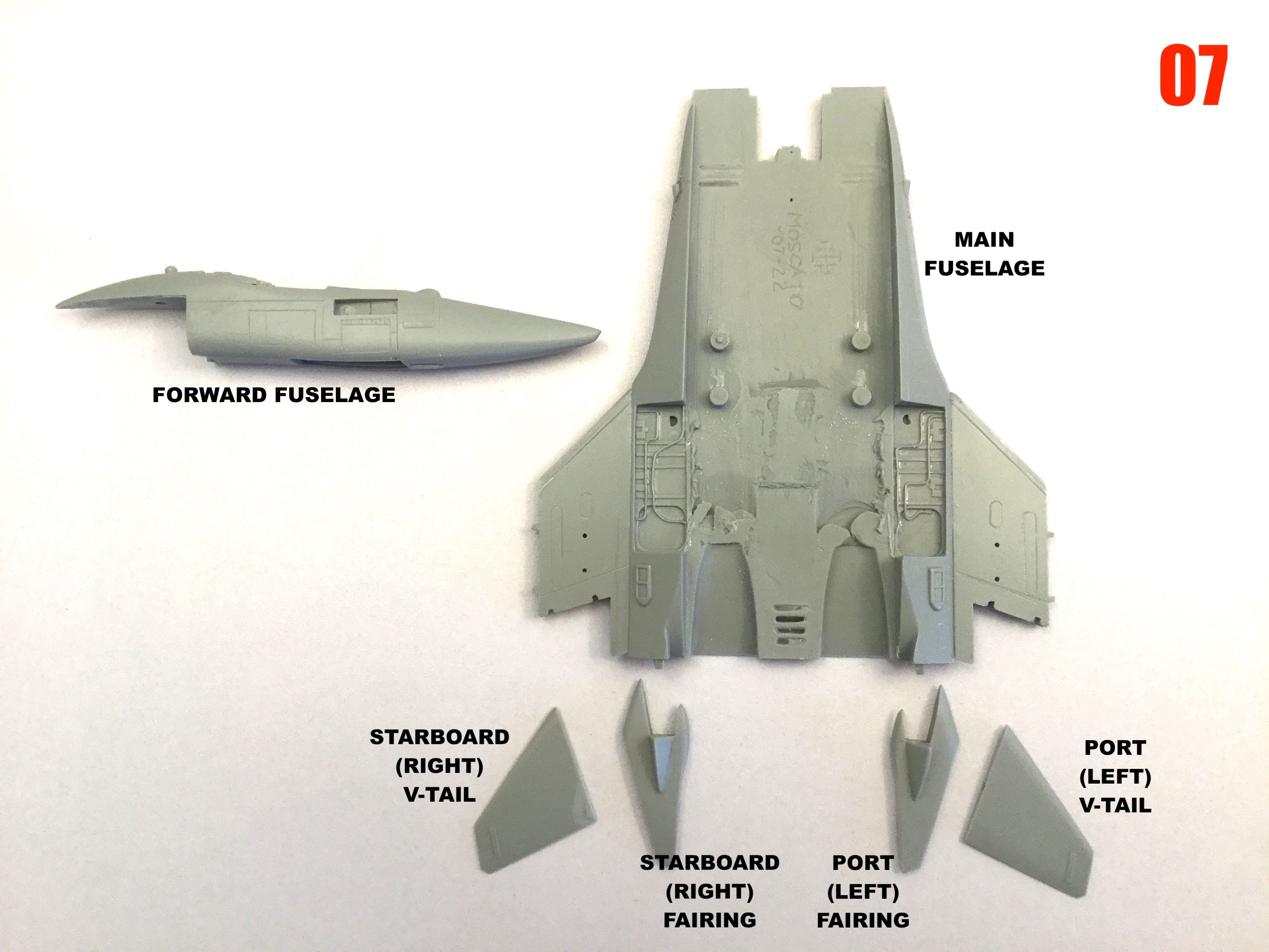
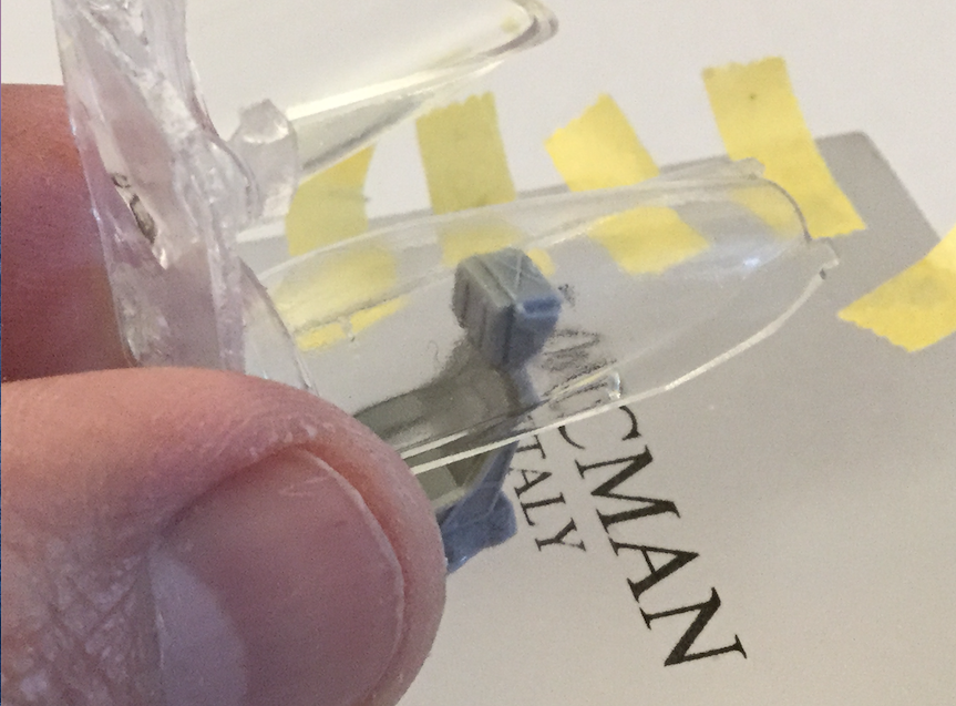
Captain's Log: Tuedsay, July 26th. 1/72 F-203B Dragunn resin kit scratchbuild update. Supply shortages are a frustrating matter! I just received my mold material yestarday, so I'll be able to complete the remaining molds... Now waiting on my resin shipment. Thankfully, I should be able to get through most of the production run with the resin I have on hand. All the tiny parts which were a concern for me have been casting very well. The clear canopies are underway as well, and looking extremely good right out of the mold. I'm also working on the markings for the fighter, which I may simply offer as free artwork that you can download & print yourself. It will also include a color & markings placement guide.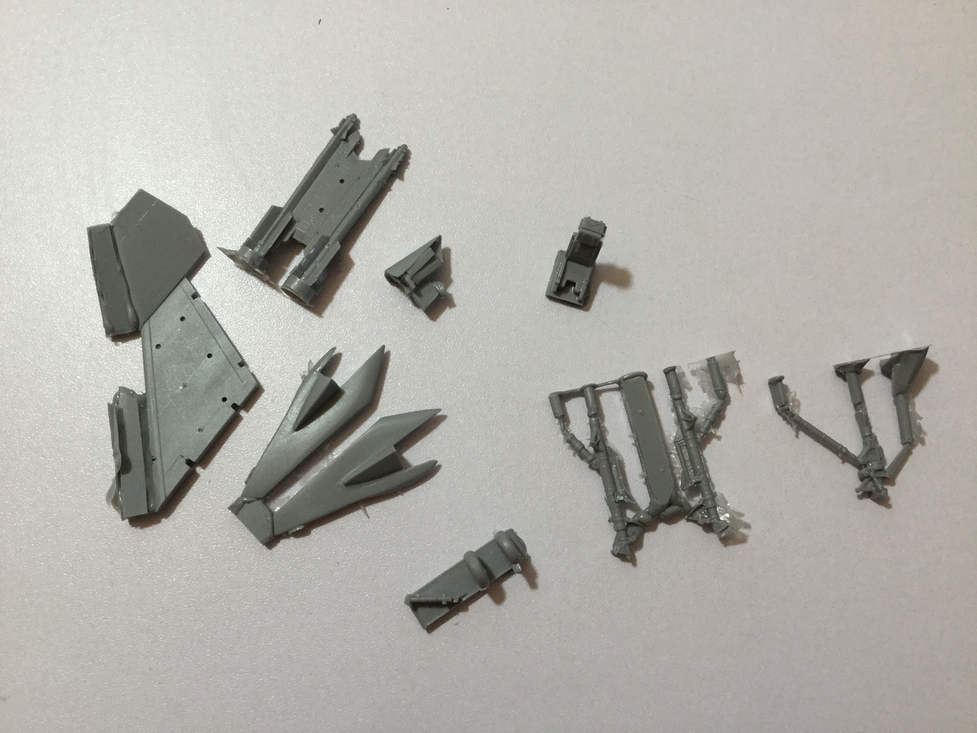
-
1/72 F203 Dragon II Kit Proposal --Moscato Hobby
captain america replied to captain america's topic in Model kits
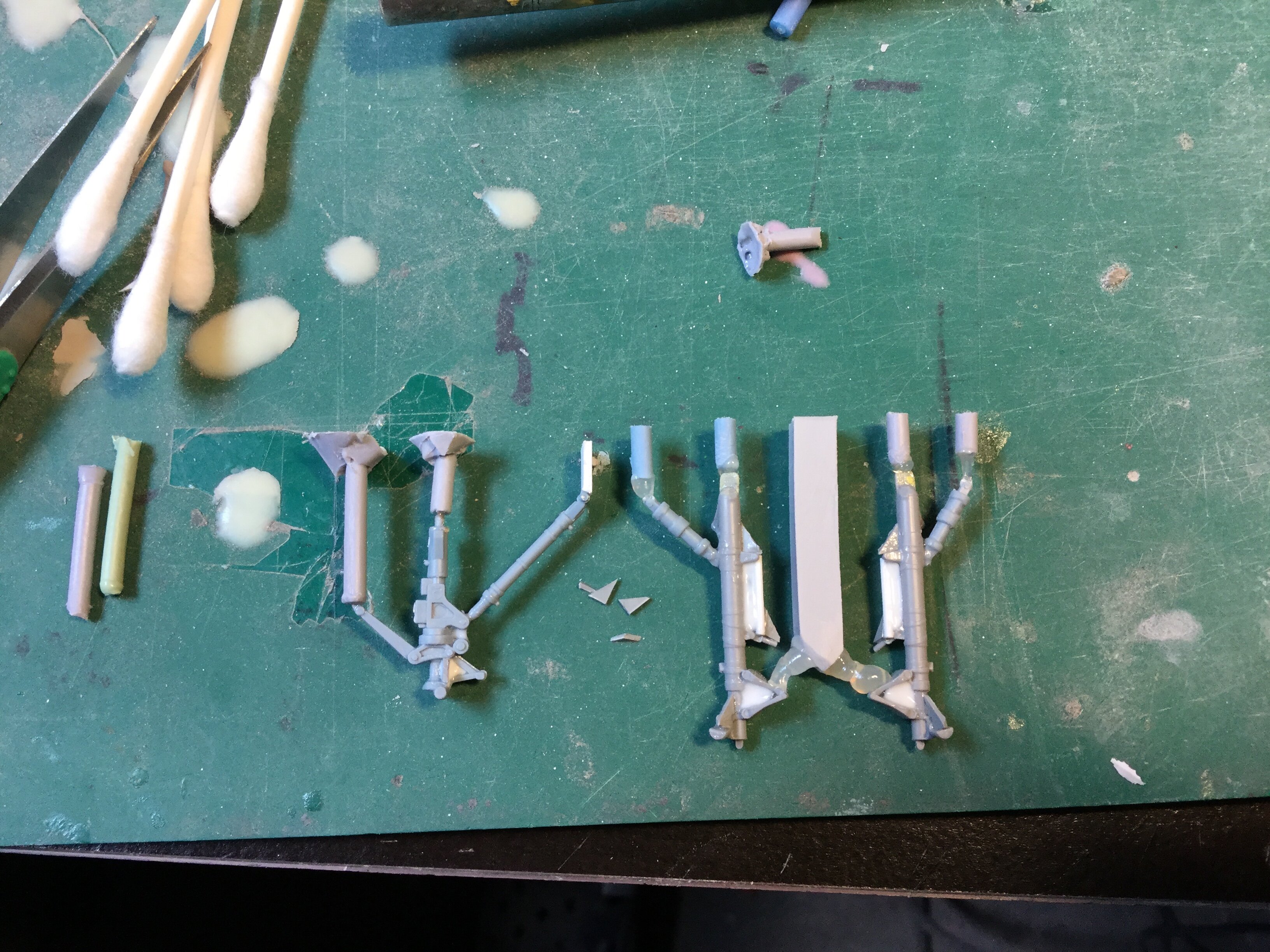
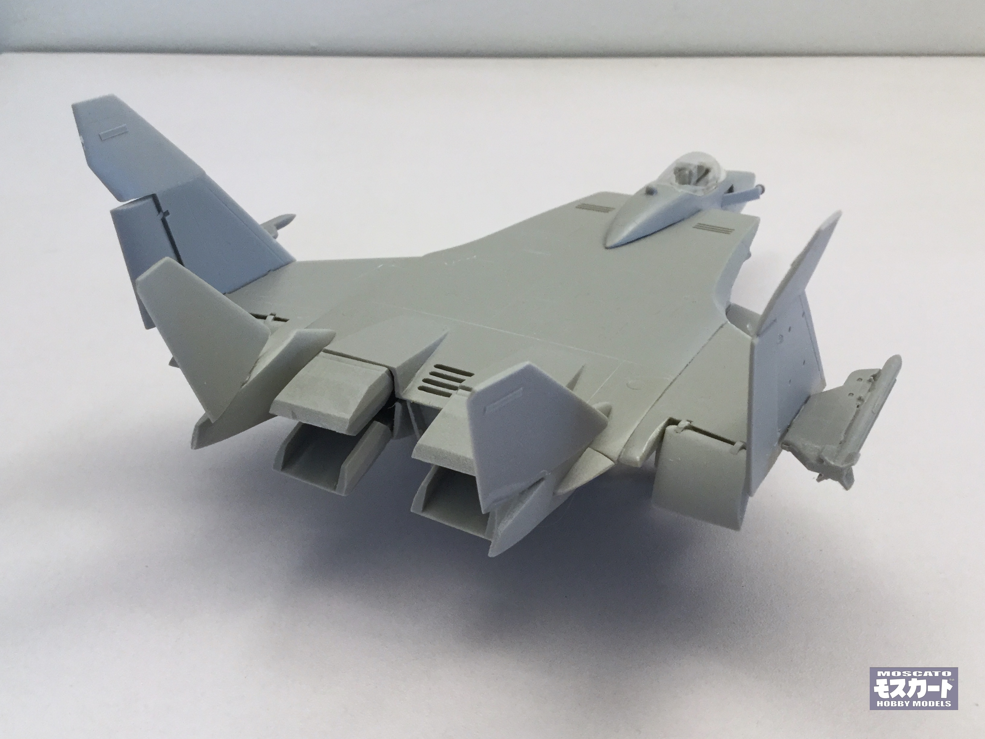
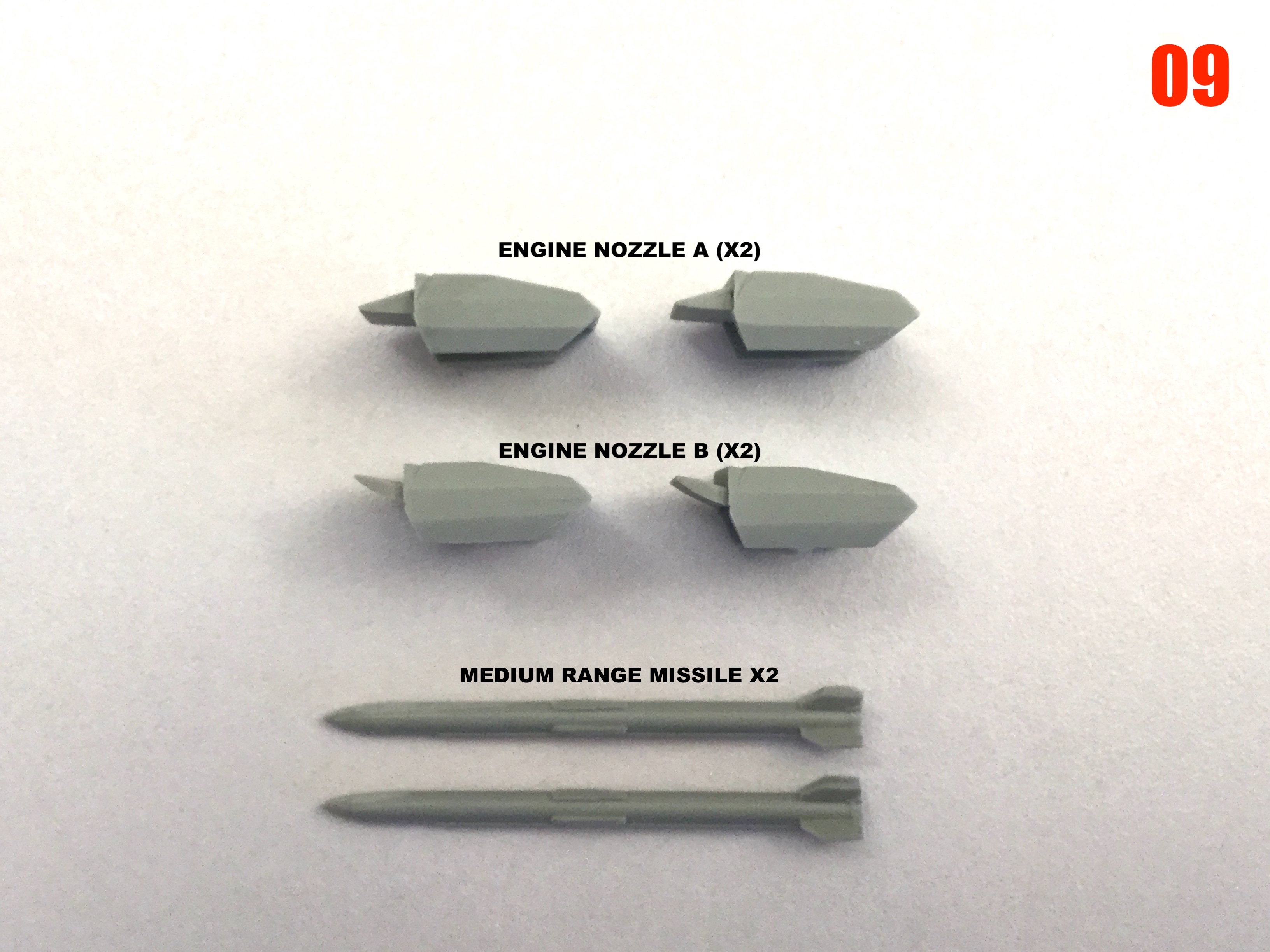
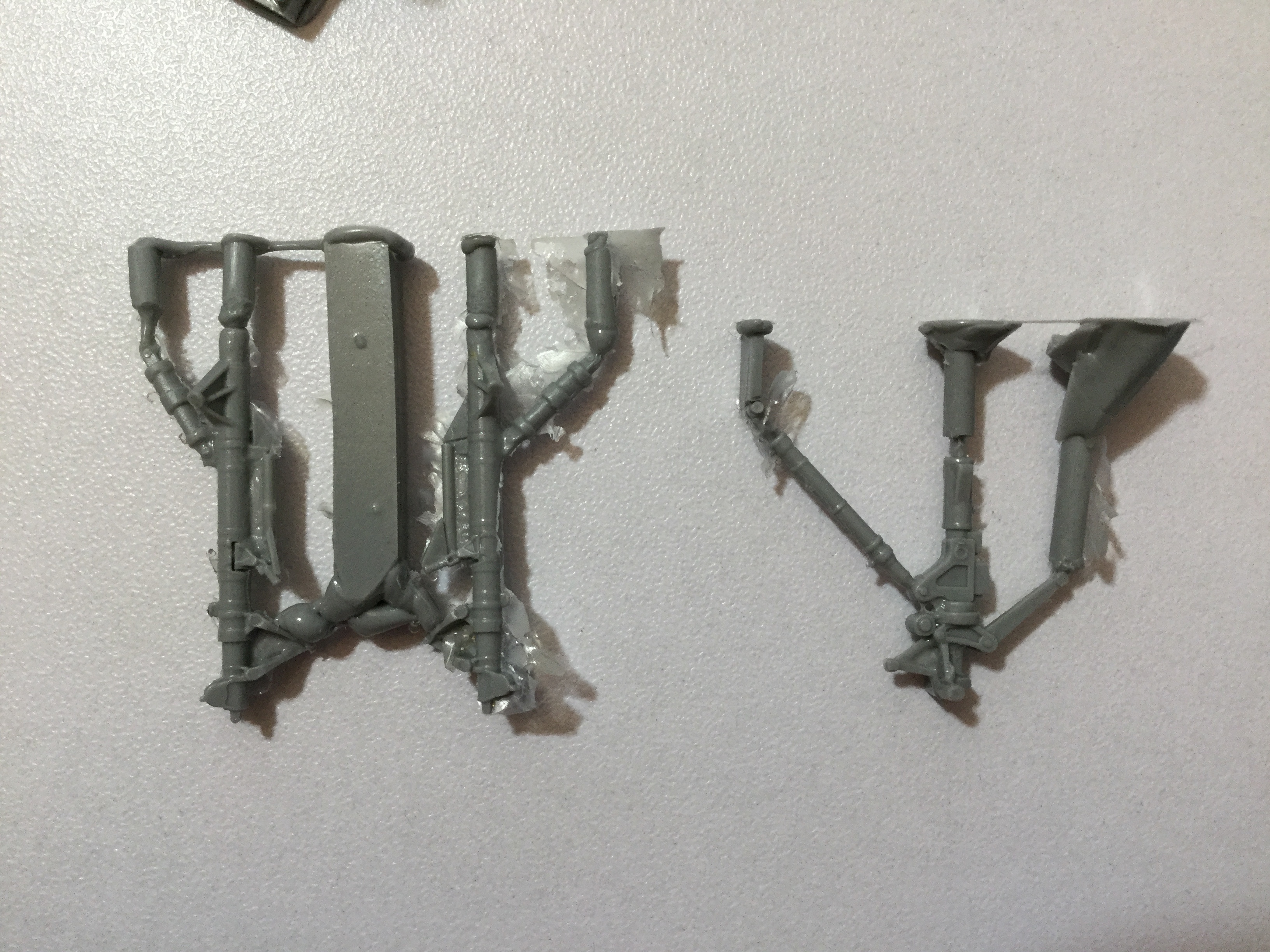
I went with smooth, simply because if I add detail to the burner can, it will only make it harder to fill that seam afterward. The way I designed it, you can putty & sand the burner, and then drop the flame ring in at the end so that it doesn't get damaged. Because of the zozzle design, the cans are quite well shrouded from most viewing angles. The ejector pin mark on the nose wheels is my bad: I should've filled them, but I forgot. More good news is that the landing gear struts all came out beautiful The main gears probably didn't need a metal insert, but I added one anyway just to be safe. At some point, we may need a 2-seat attack variant of this thing. -
1/72 F203 Dragon II Kit Proposal --Moscato Hobby
captain america replied to captain america's topic in Model kits
Captain's Log: Monday, July 18th, 2022. Molding is going well! The bulk of the masters have now been molded, but because everything is either slow or delayed these days, I'm waiting on the materials I need to finish the remainder of the molds, so the frustration continues. As such, I'll use this time to try to mold as many of the very delicate parts as I can and get those out of the way.