captain america
-
Posts
3549 -
Joined
-
Last visited
Content Type
Profiles
Forums
Events
Gallery
Everything posted by captain america
-

1/48 SOUTHERN CROSS BIOROID PART II
captain america replied to captain america's topic in Anime or Science Fiction
The destructions!
-
I'm hopeful for an all-opaque version of this. I like the buster, but not the translucent amber plastic.
-
1/48 SOUTHERN CROSS BIOROID PART II
captain america replied to captain america's topic in Anime or Science Fiction
Captain's Build Update: production is nearing its close, just a few more kits to cast. Even BUG FACE is impressed! Those of you who opted for the hover-sled option will notice a few improvements to the masters in the form of more faithful detailing. Just little things, but those little things make a difference. Instructions will be ready early next week. Stay tuned!
-
1/48 SOUTHERN CROSS BIOROID PART II
captain america replied to captain america's topic in Anime or Science Fiction
Ask, and ye shall receive.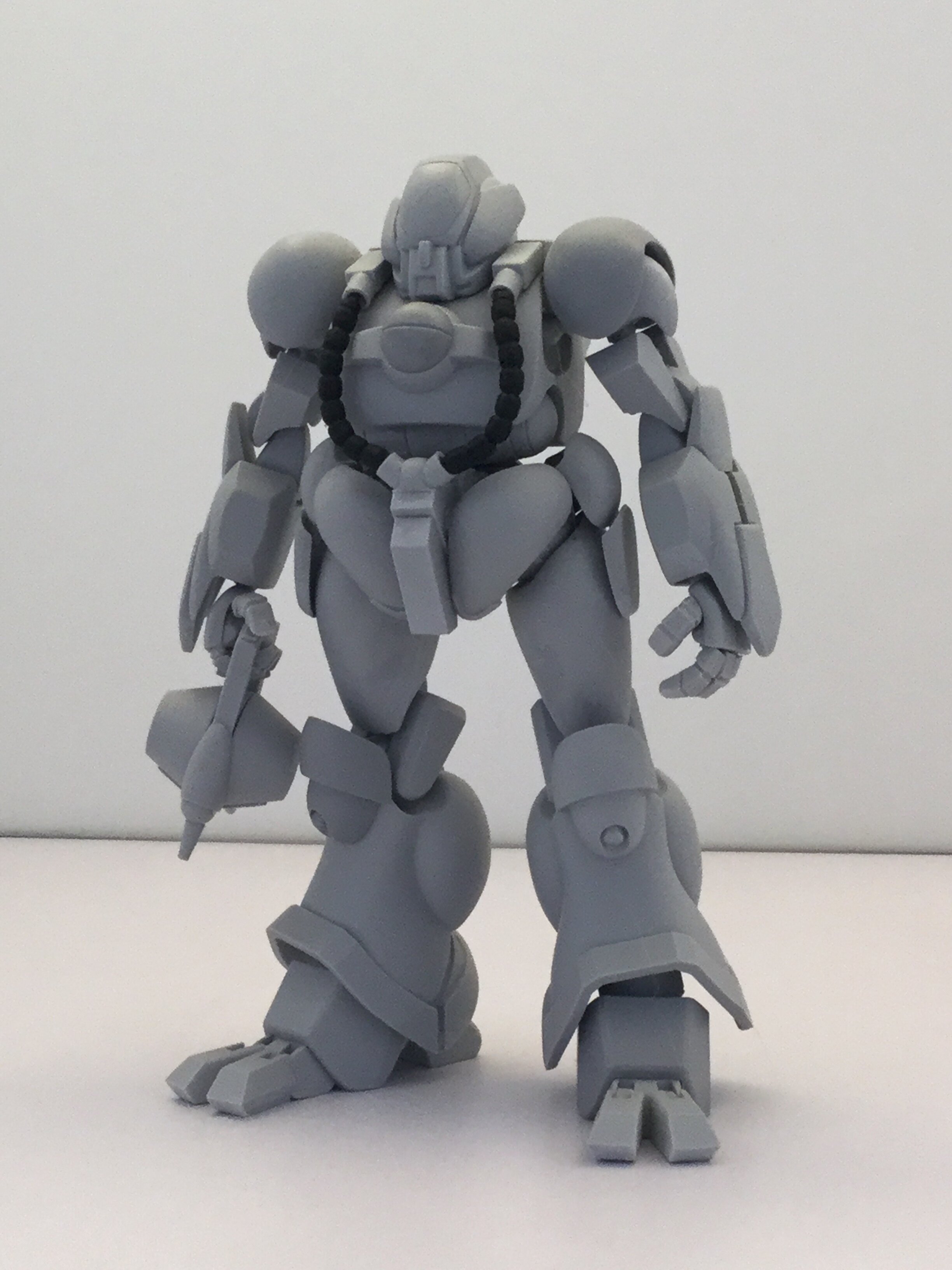
- 150 replies
-
- 3
-

-
- southern cross
- robotech
- (and 4 more)
-
1/48 SOUTHERN CROSS BIOROID PART II
captain america replied to captain america's topic in Anime or Science Fiction
Admittedly, the bar wasn't set very high to begin with, but thanks. -
1/48 SOUTHERN CROSS BIOROID PART II
captain america replied to captain america's topic in Anime or Science Fiction
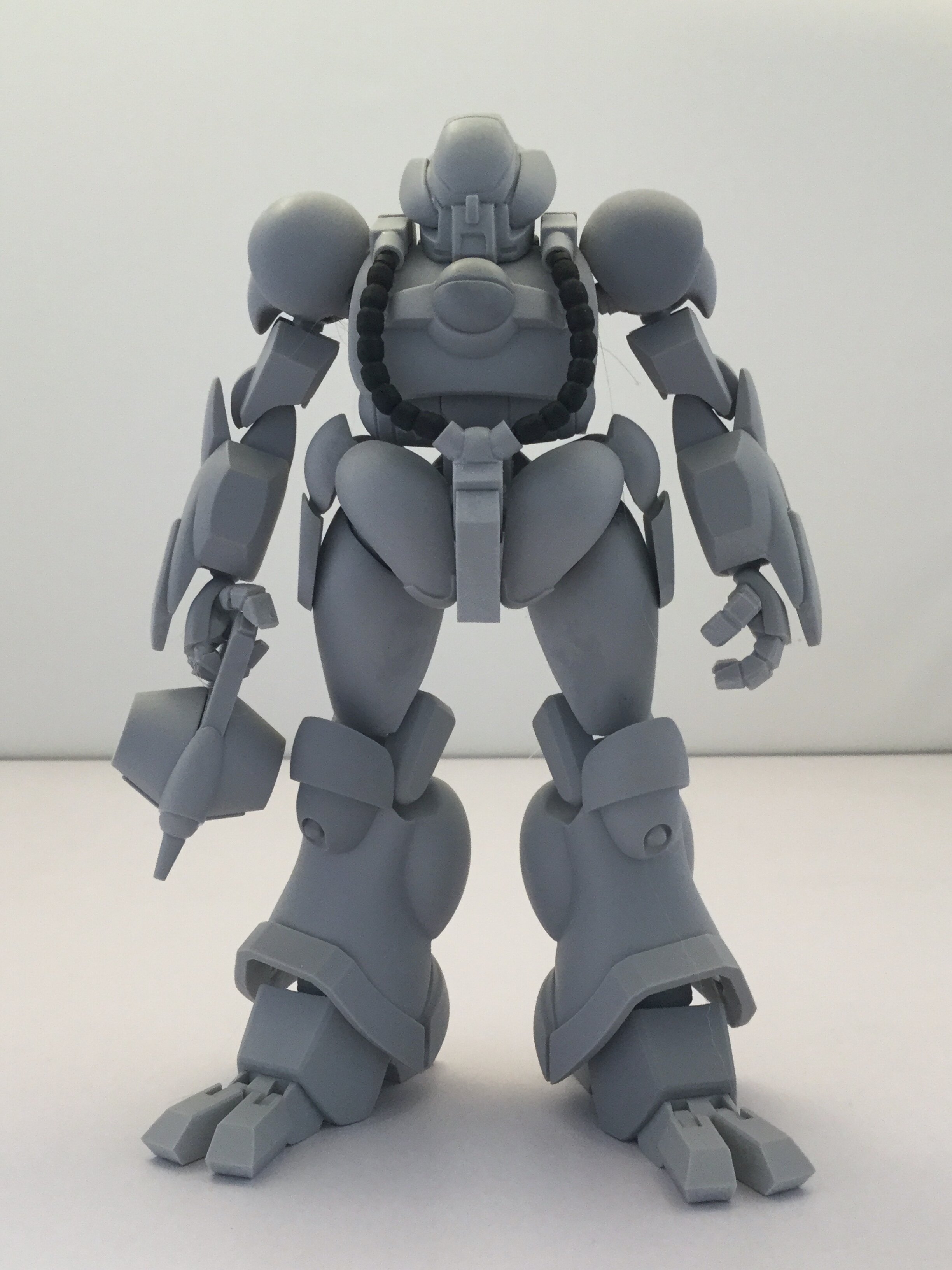
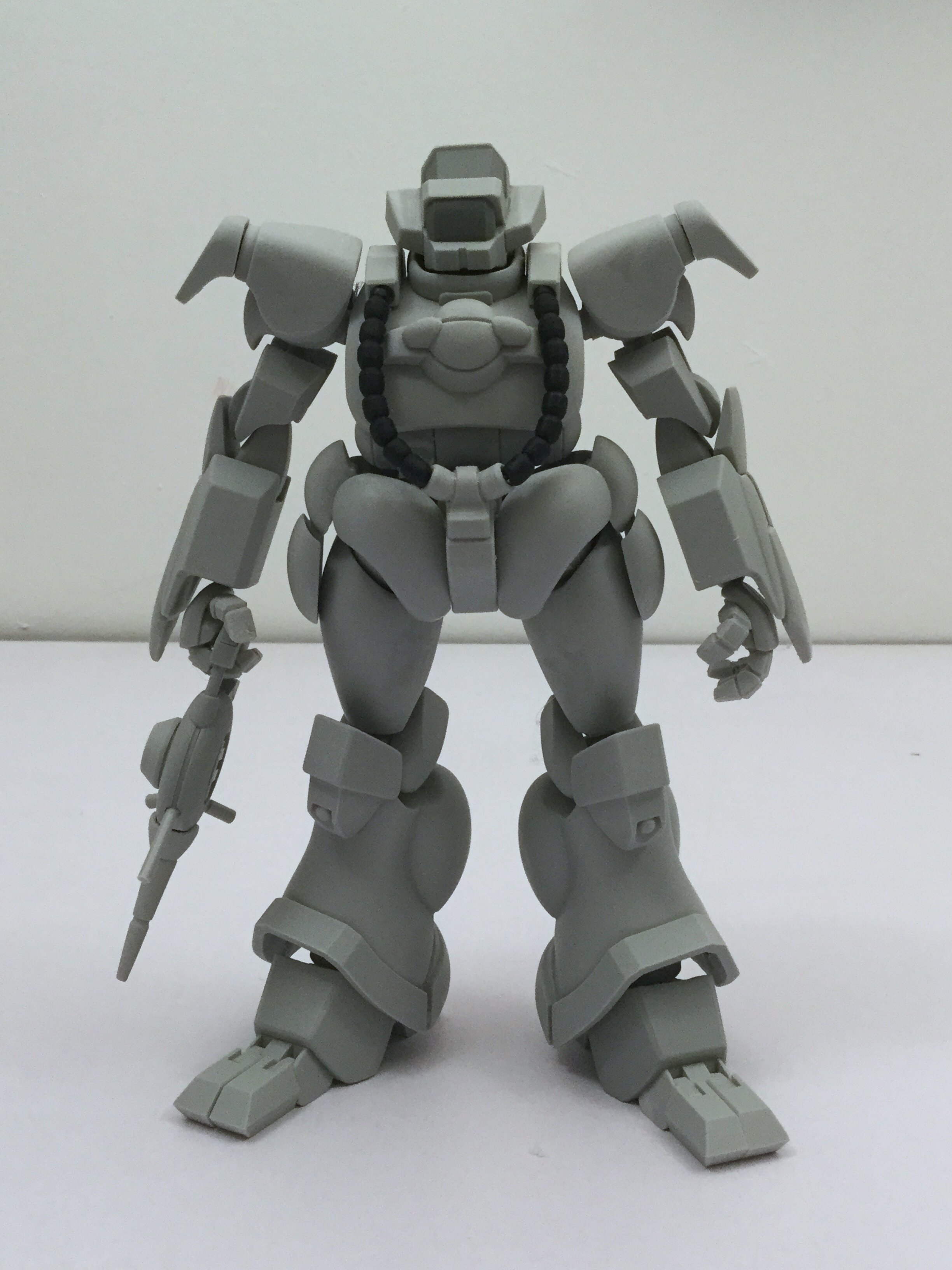
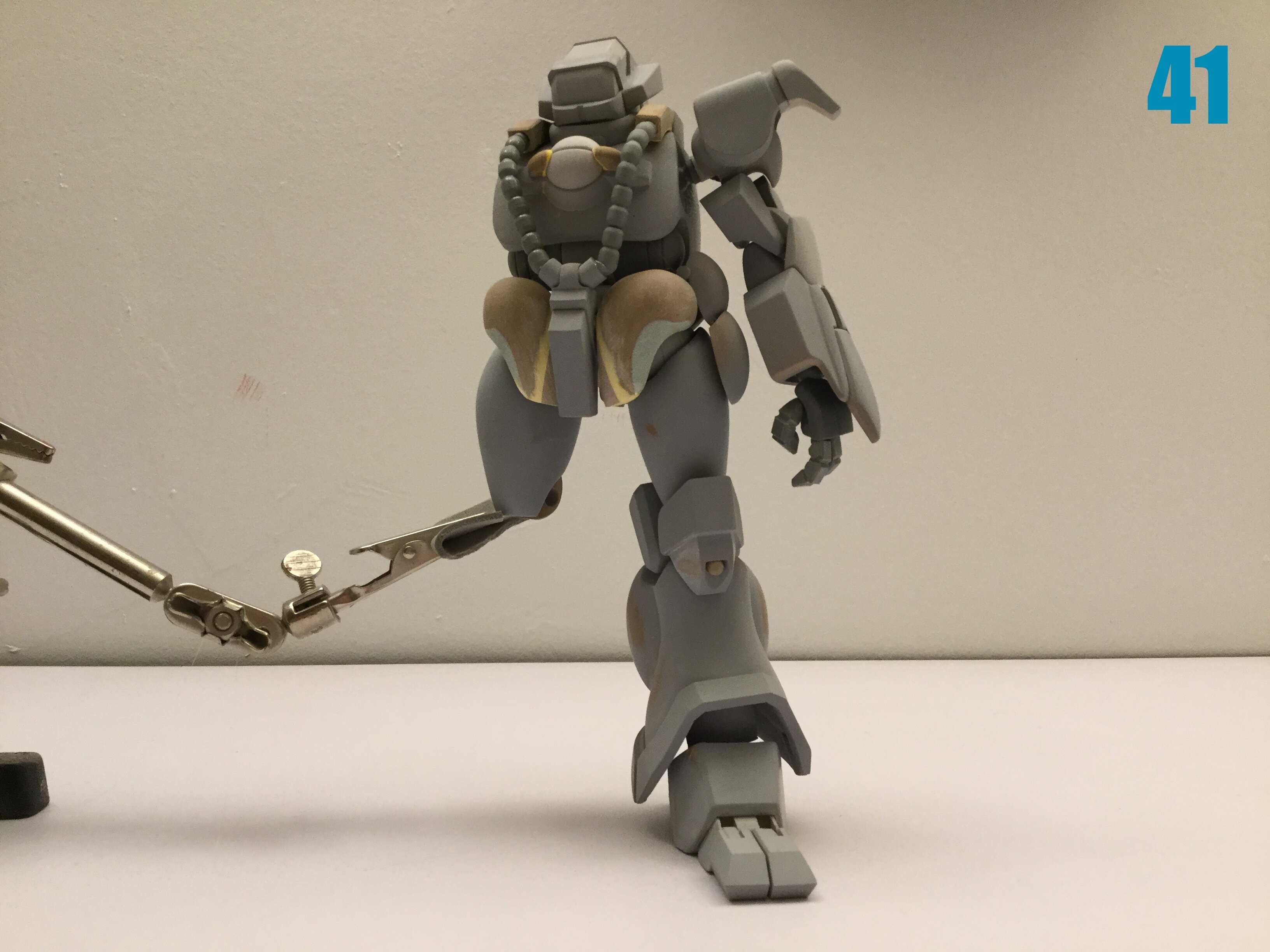
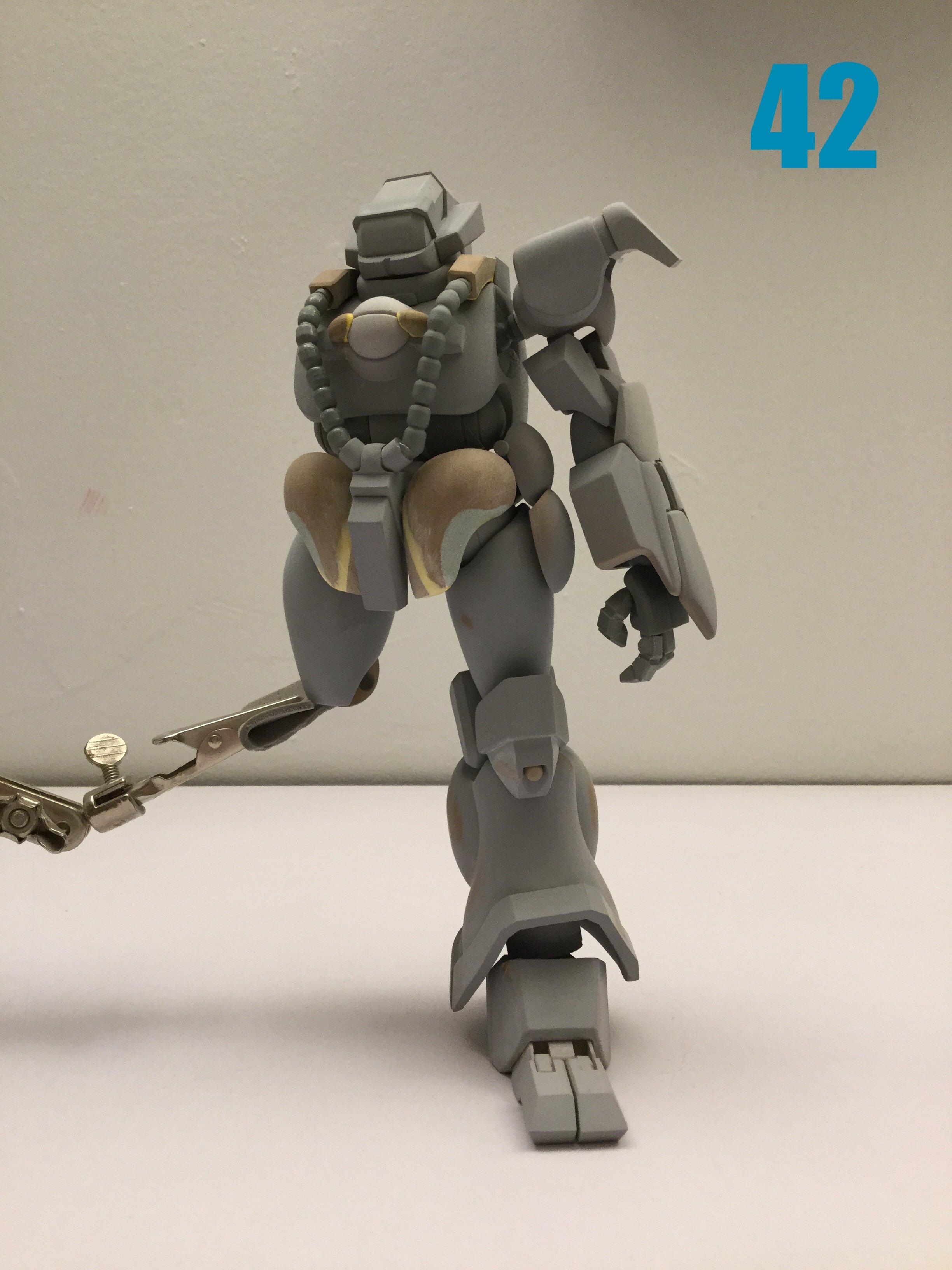
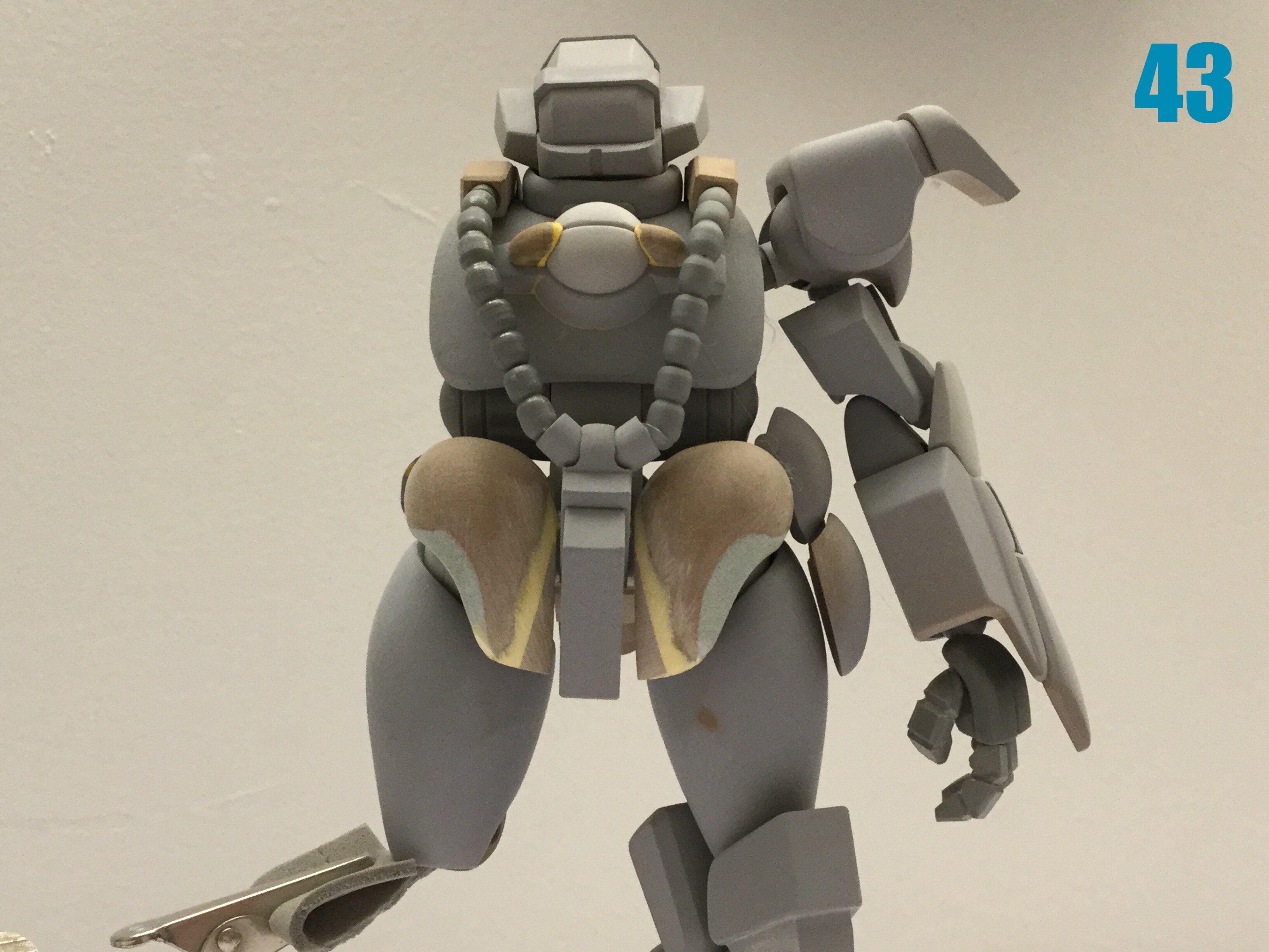
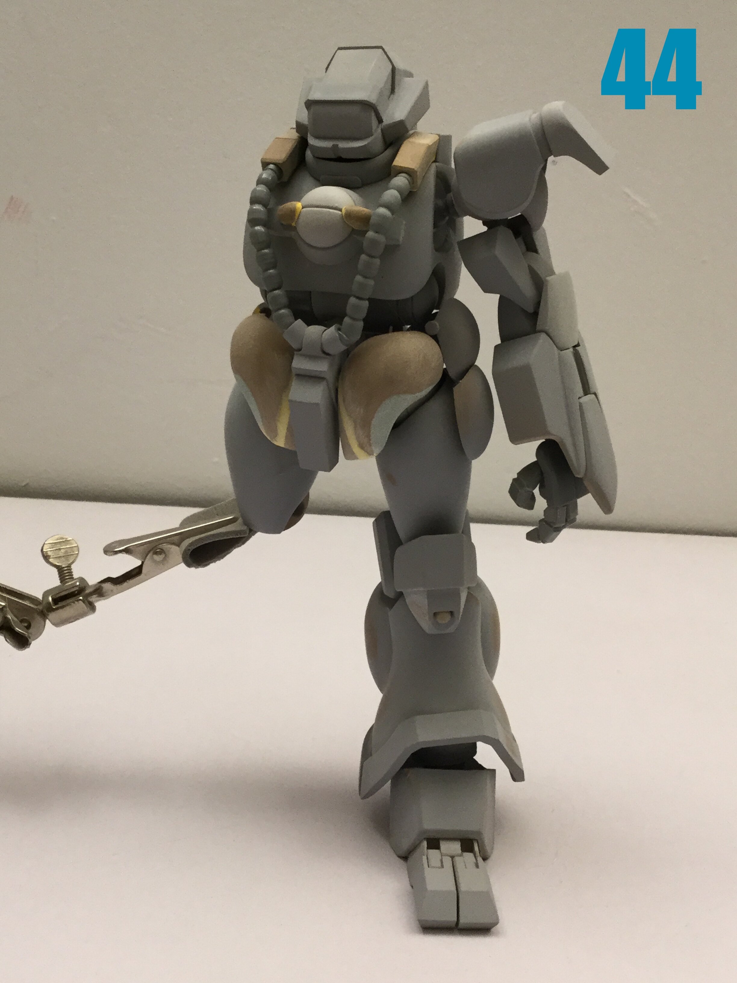
Bam! Finished, suckahs! I'll have some Bug Face pics next week, once I get over this casting hump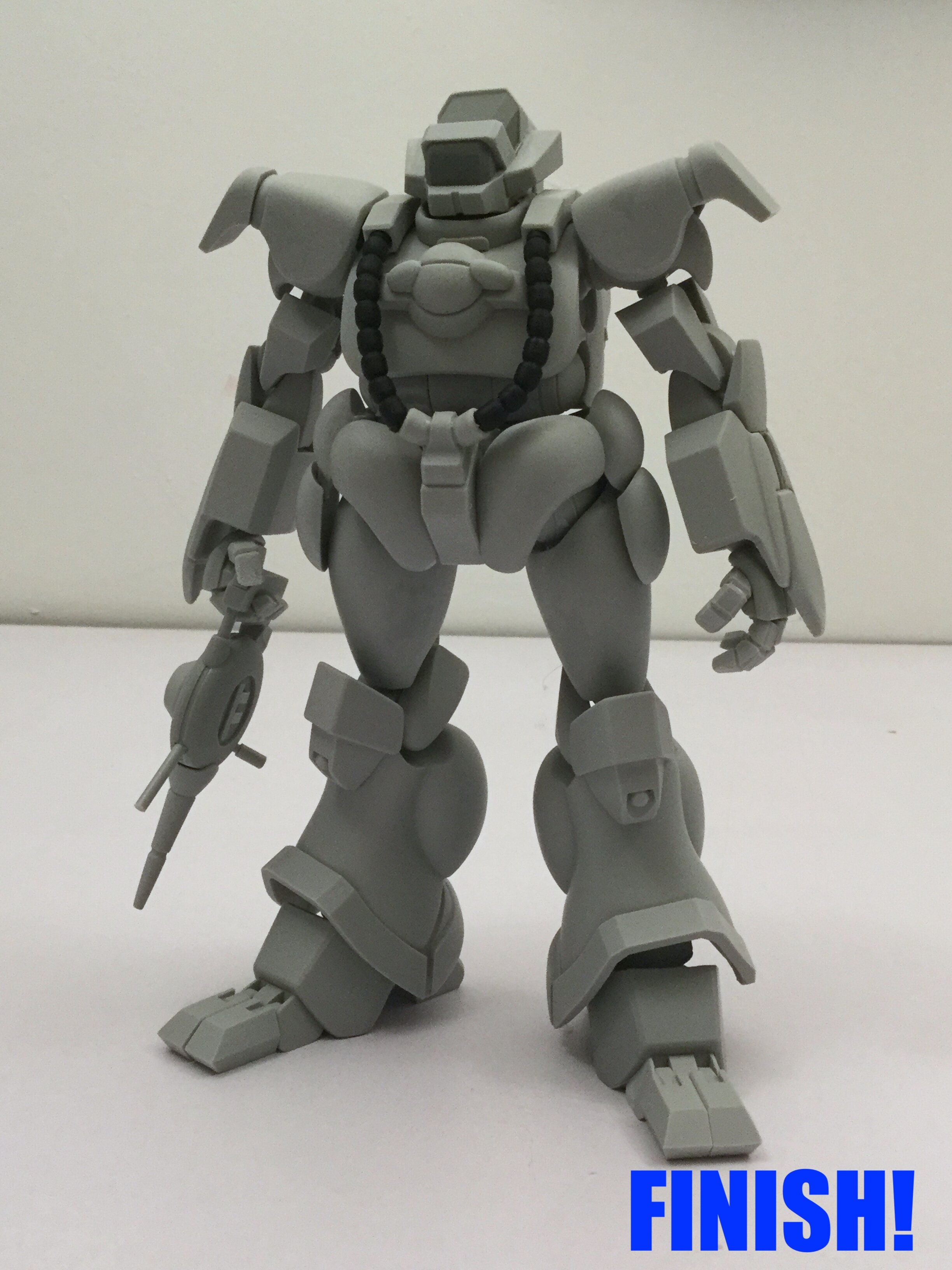
-
1/48 SOUTHERN CROSS BIOROID PART II
captain america replied to captain america's topic in Anime or Science Fiction
For what it's worth, I started scratchbuilding precisely because I got tired of having to "fix things" on those same plastic kits. It might seem like a daunting task to build something from scratch if you've never done it, but consider this: if you can scratchbuild one or two small parts for your plastic model, a full scratchbuild is just an extension of that process, and it's done one part at a time. Doing it manually is also theraputic for me, but I certainly don't discount the value of virtual modeling for some more geomertically complex parts. -
1/48 SOUTHERN CROSS BIOROID PART II
captain america replied to captain america's topic in Anime or Science Fiction
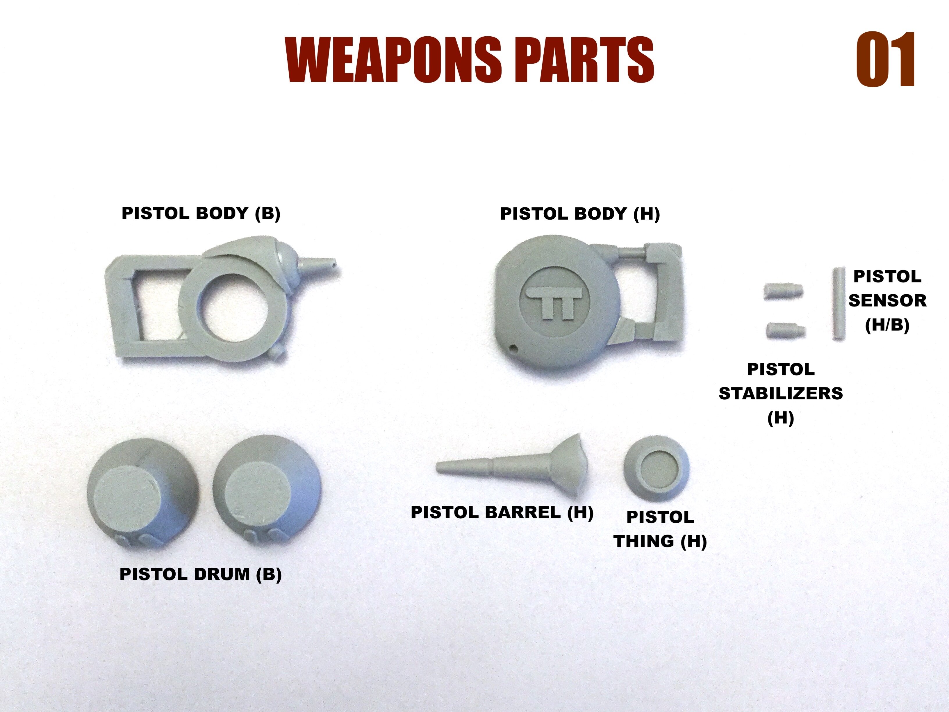
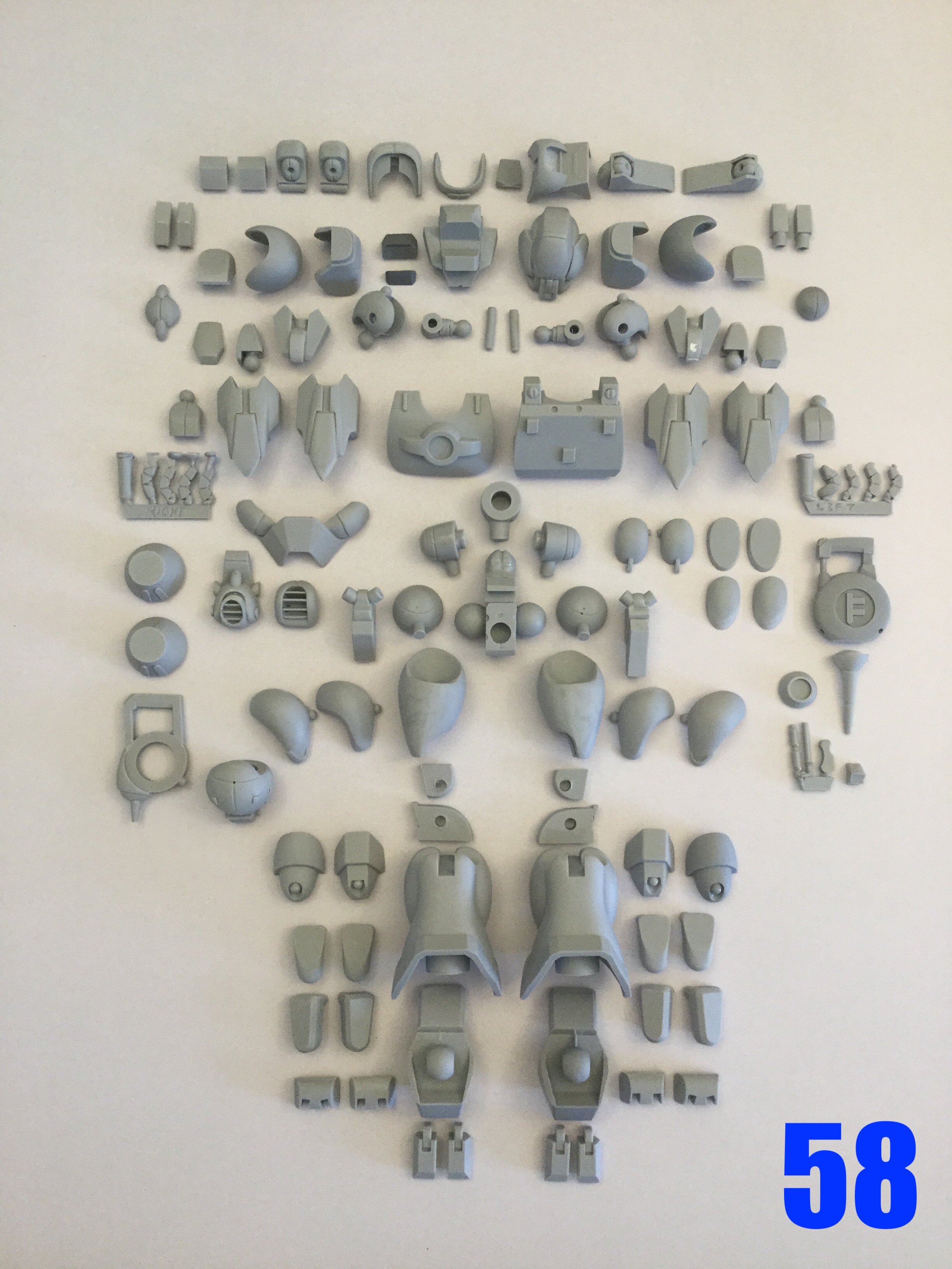
Captain's log: Friday, March 4th 2022. The molds are done, and the castings are looking excellent! It was quite an ordeal getting everything finished, but it was 20+ lbs of silicone put to good use, and the process went much more smoothly than I was expecting. The robot itself is a whopping 117 parts, and add another 21 parts for the sled. I will begin production in earnest on Monday, so shipping is maybe 3-4 weeks out. I'll have pics of the completed mecha this coming week, so be sure to stay tuned!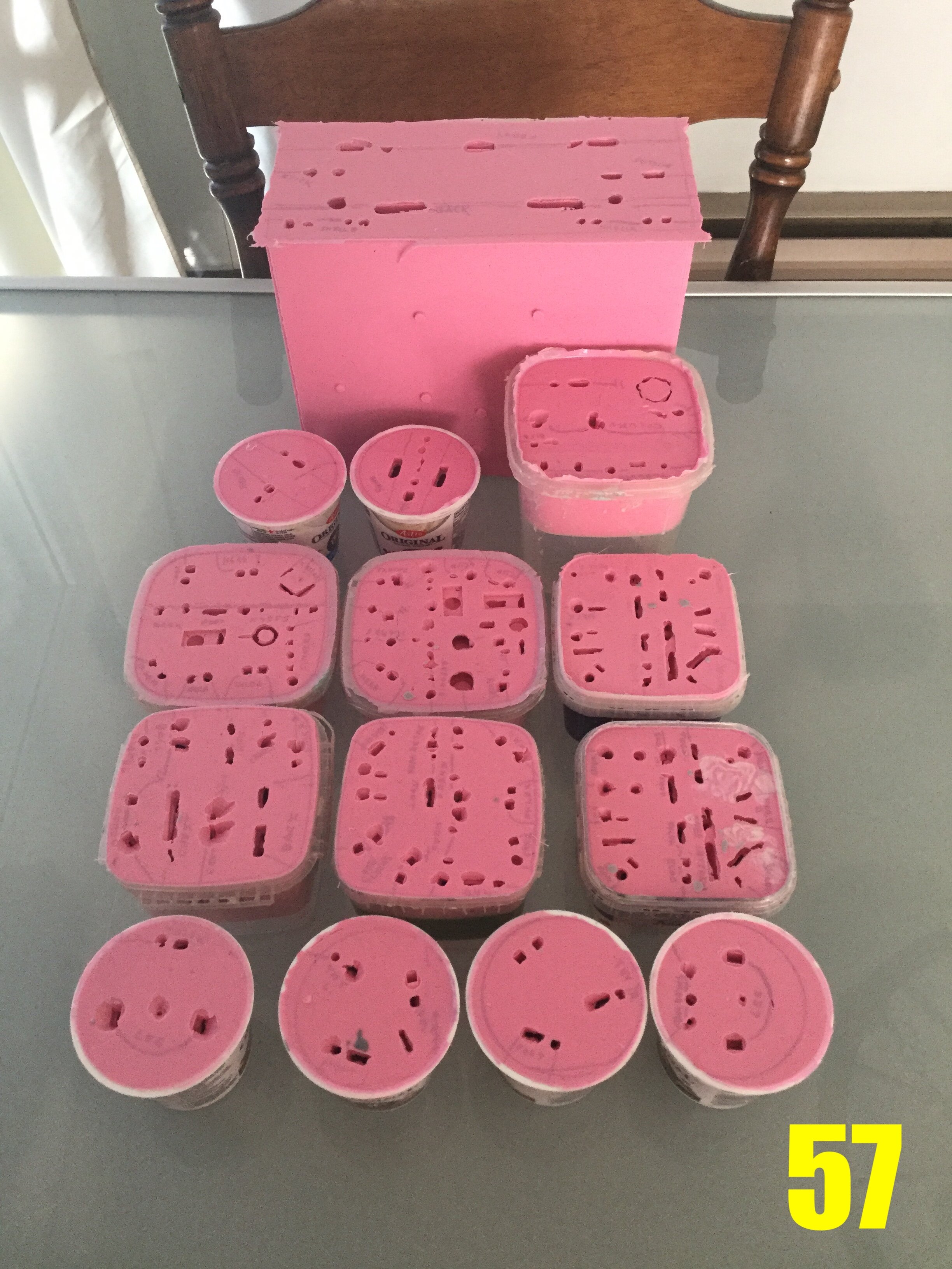
- 150 replies
-
- 4
-
-
- southern cross
- robotech
- (and 4 more)
-
1/48 SOUTHERN CROSS BIOROID PART II
captain america replied to captain america's topic in Anime or Science Fiction
Me too! I just finished the molds today, what a grueling task it is. All. That. Silicone! I actually have most of the parts for 1 kit cast already, so full mock-up pics are coming next wee. Hopefully tomorrow I can show you all the molds and an exploded view if the kit parts.- 150 replies
-
- 1
-
-
- southern cross
- robotech
- (and 4 more)
-
1/48 SOUTHERN CROSS BIOROID PART II
captain america replied to captain america's topic in Anime or Science Fiction
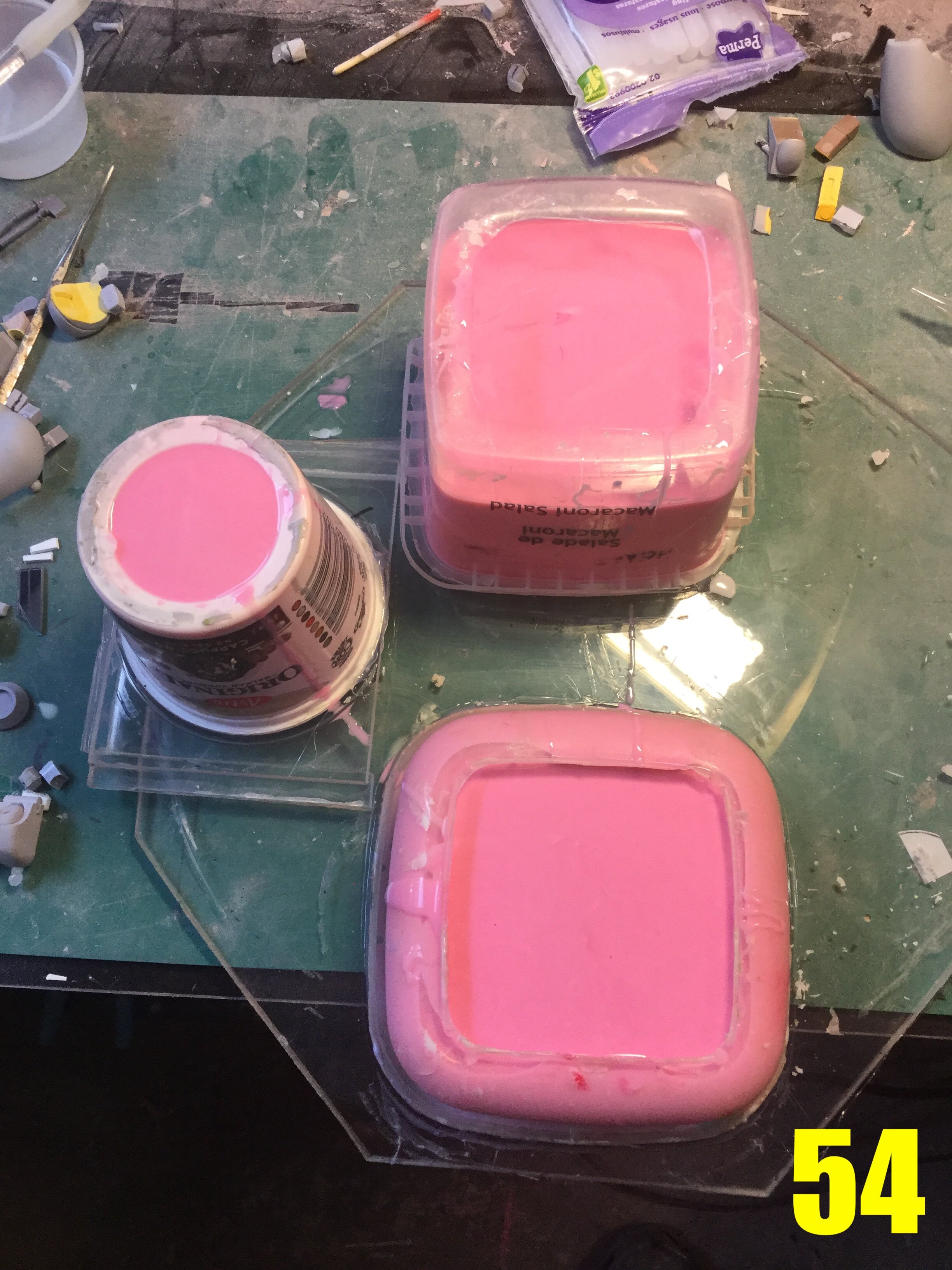
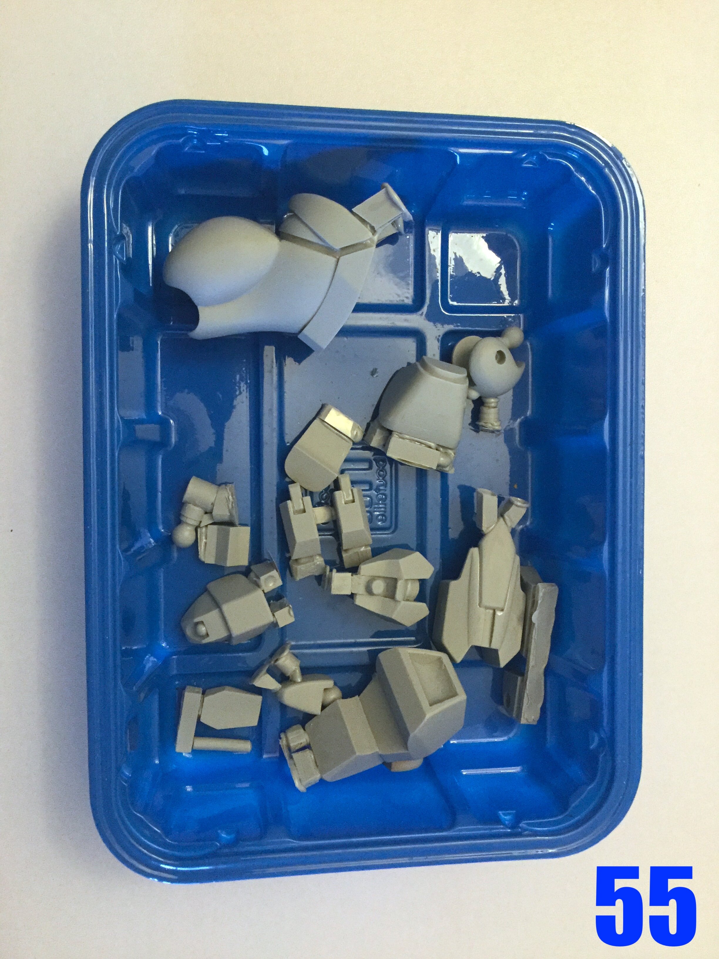
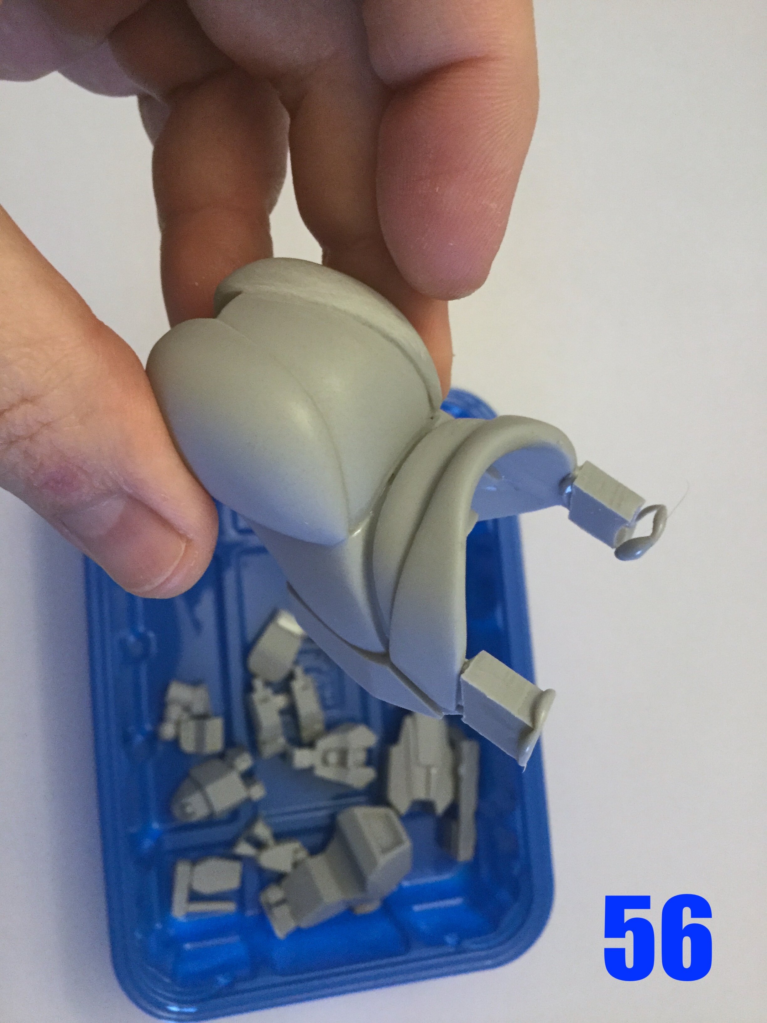
Captain's log: Thursday, February 24th, 2022. Molds are underway! The process is a tedious one, for several parts need to be duplicated (left and right), then others need to be molded for one configuration, then that same part cast and modified to suit the other configuration... And then those parts need to be duplicated, too! Pic 53 shows some of those mold boxes ready to receive the silicone matrix, which when hardened, will become molds and the masters extracted. Some of the very best mold boxes in my arsenal are made from recycled food containers beause they're tough, moderately flexible, and resist resin exceedingly well. Pic 54 shows those same molds with the pink silicone goop having been freshly poured. Pics 55 and 56 are the resin fruits of those molds, looking excellent! There are still several molds to pour, but I'm very much past the mid-way. Stay tuned!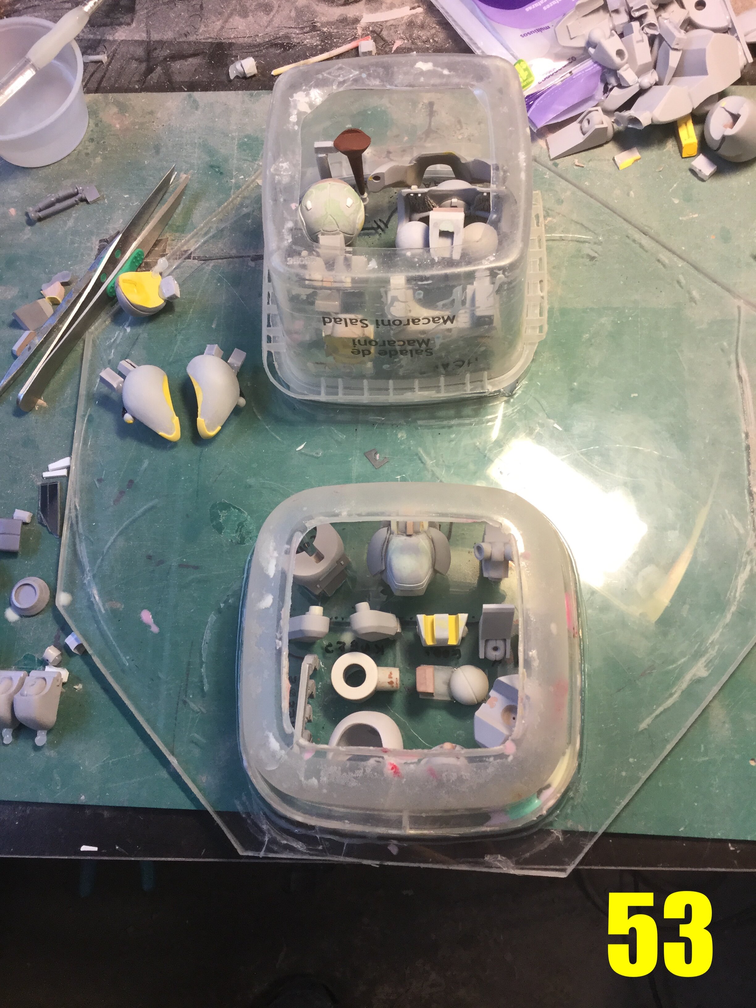
- 150 replies
-
- 2
-
-
- southern cross
- robotech
- (and 4 more)
-
1/48 SOUTHERN CROSS BIOROID PART II
captain america replied to captain america's topic in Anime or Science Fiction
Just be sure to get your orders in by Friday, guys. After that, the pre-order window will be closed. -
1/48 SOUTHERN CROSS BIOROID PART II
captain america replied to captain america's topic in Anime or Science Fiction
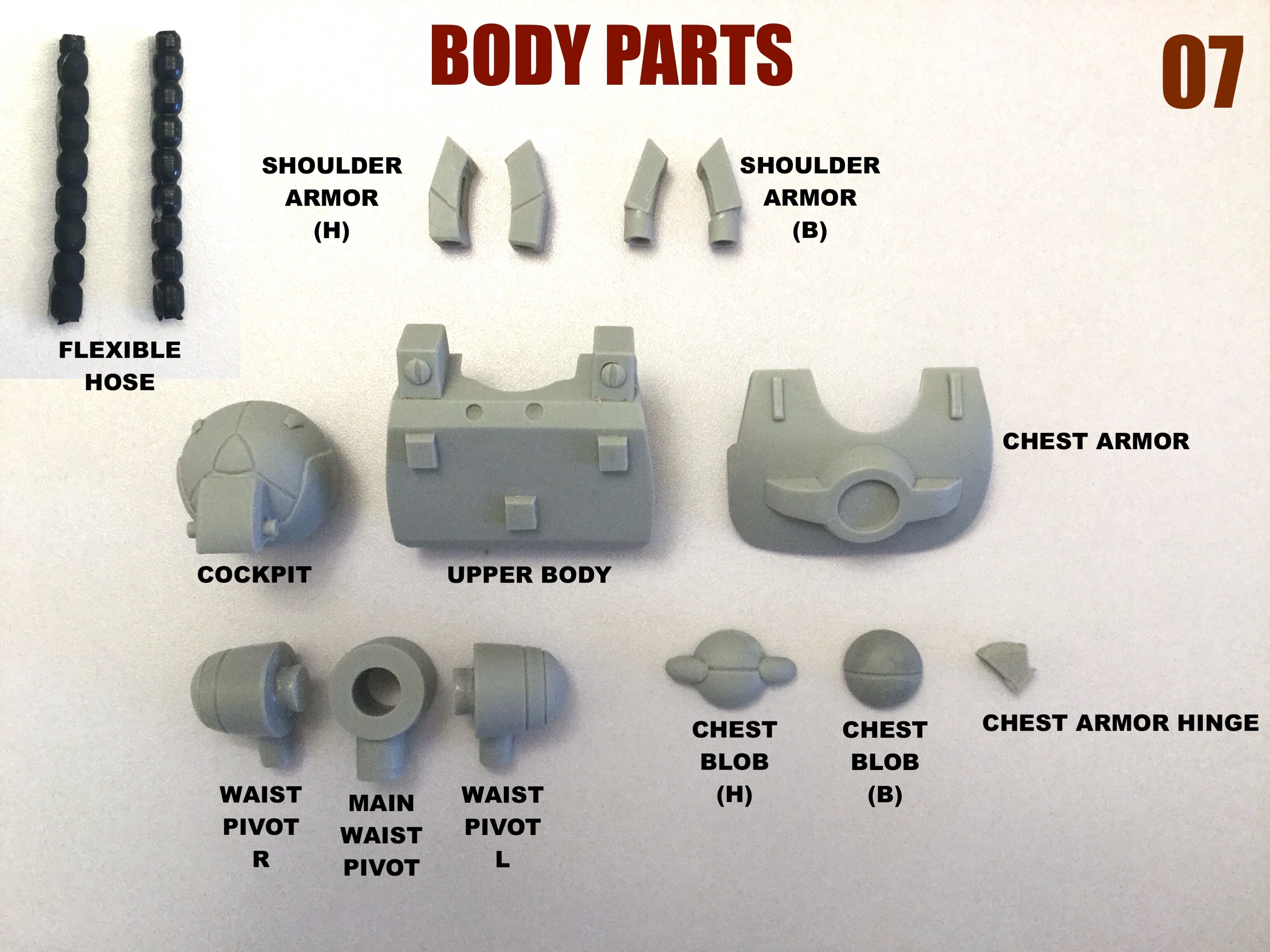
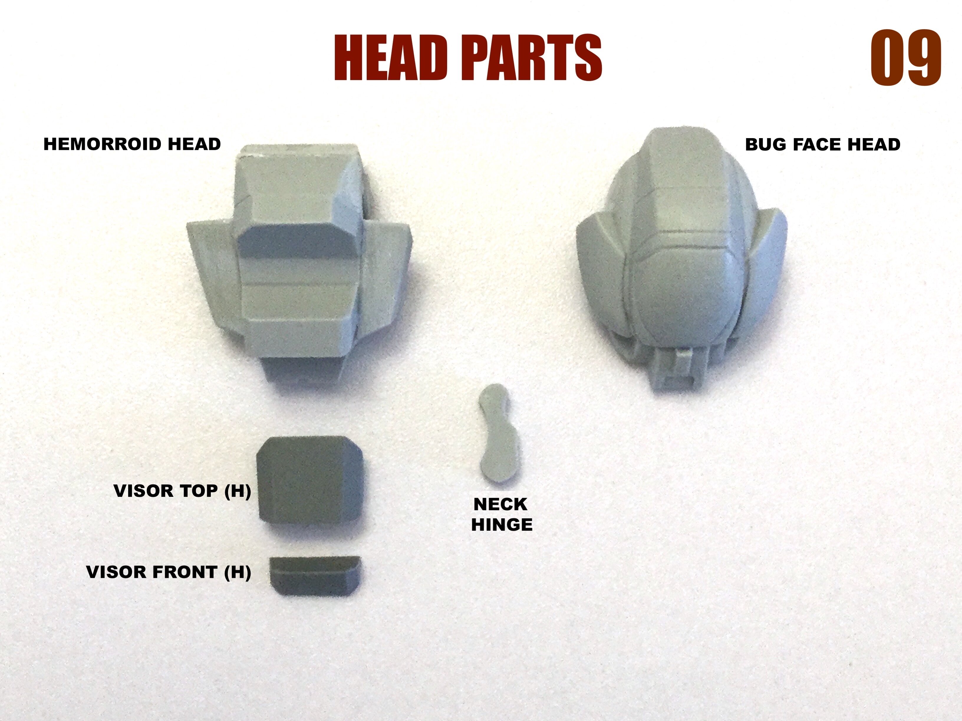
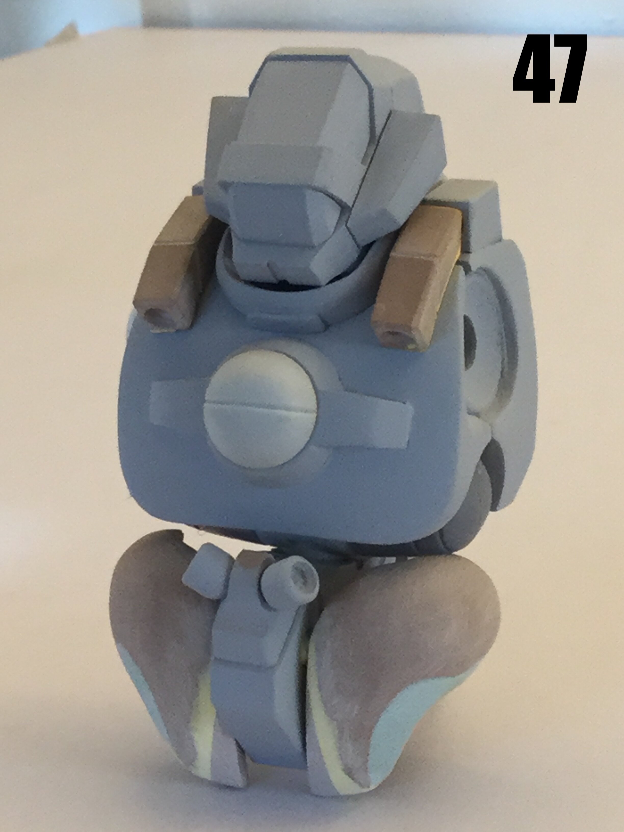
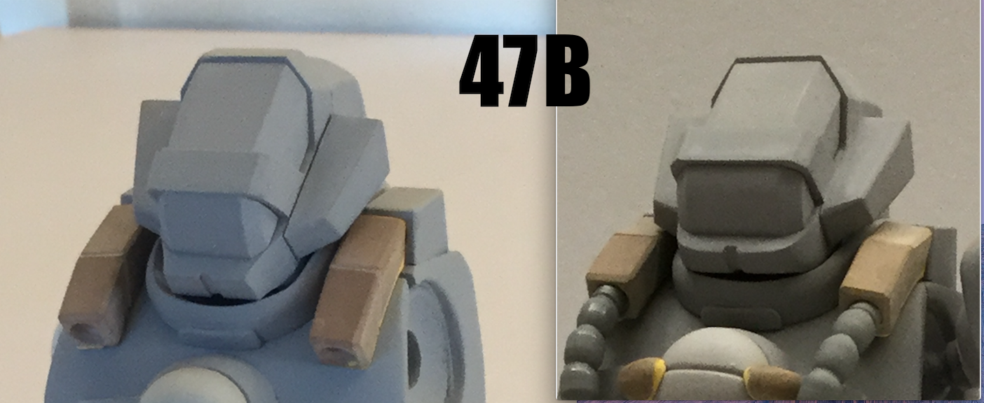
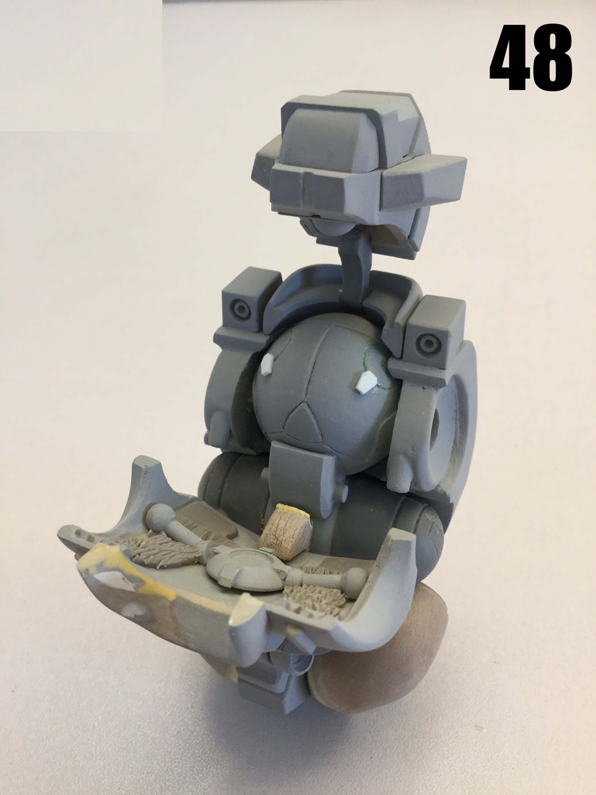
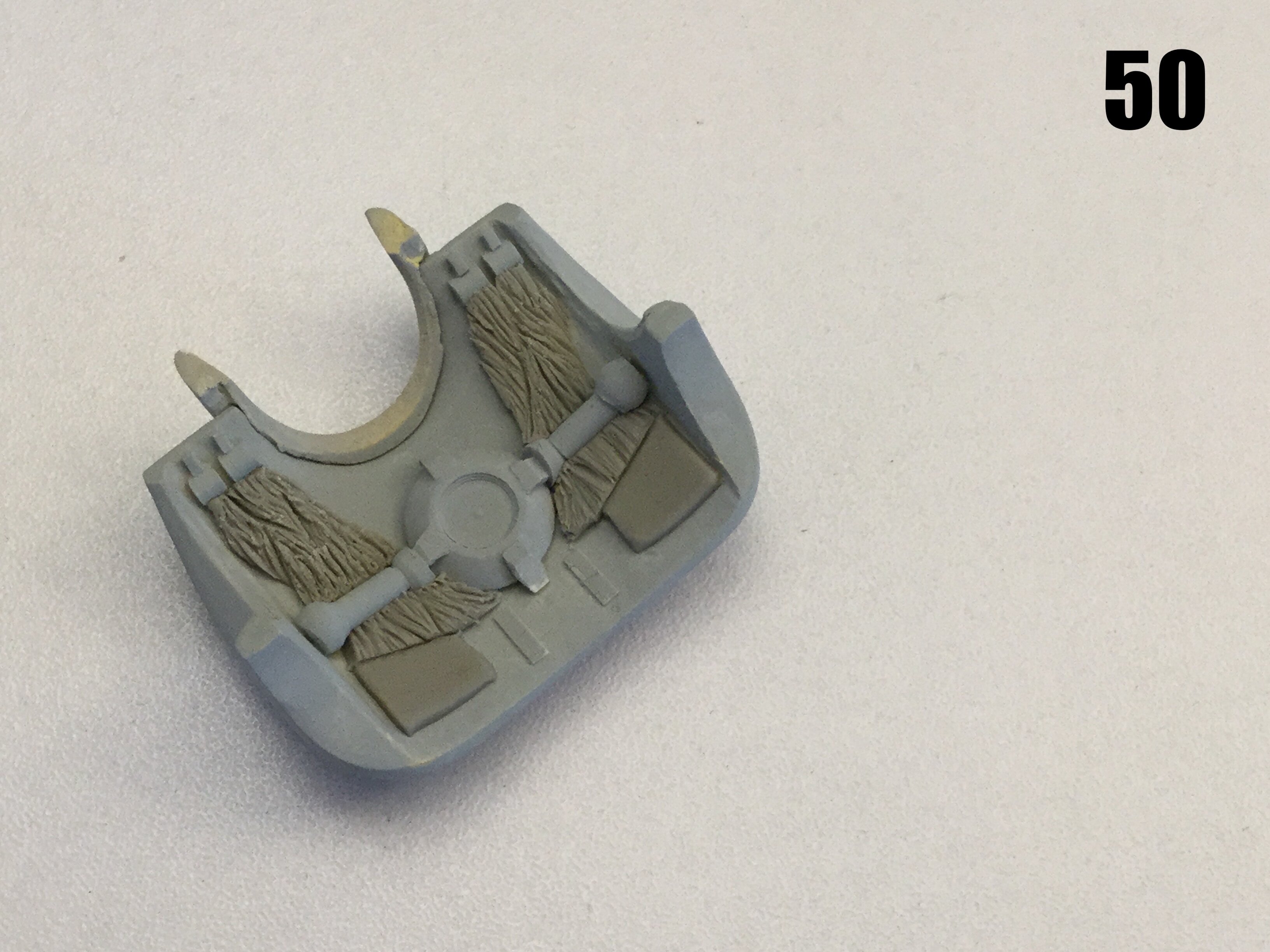
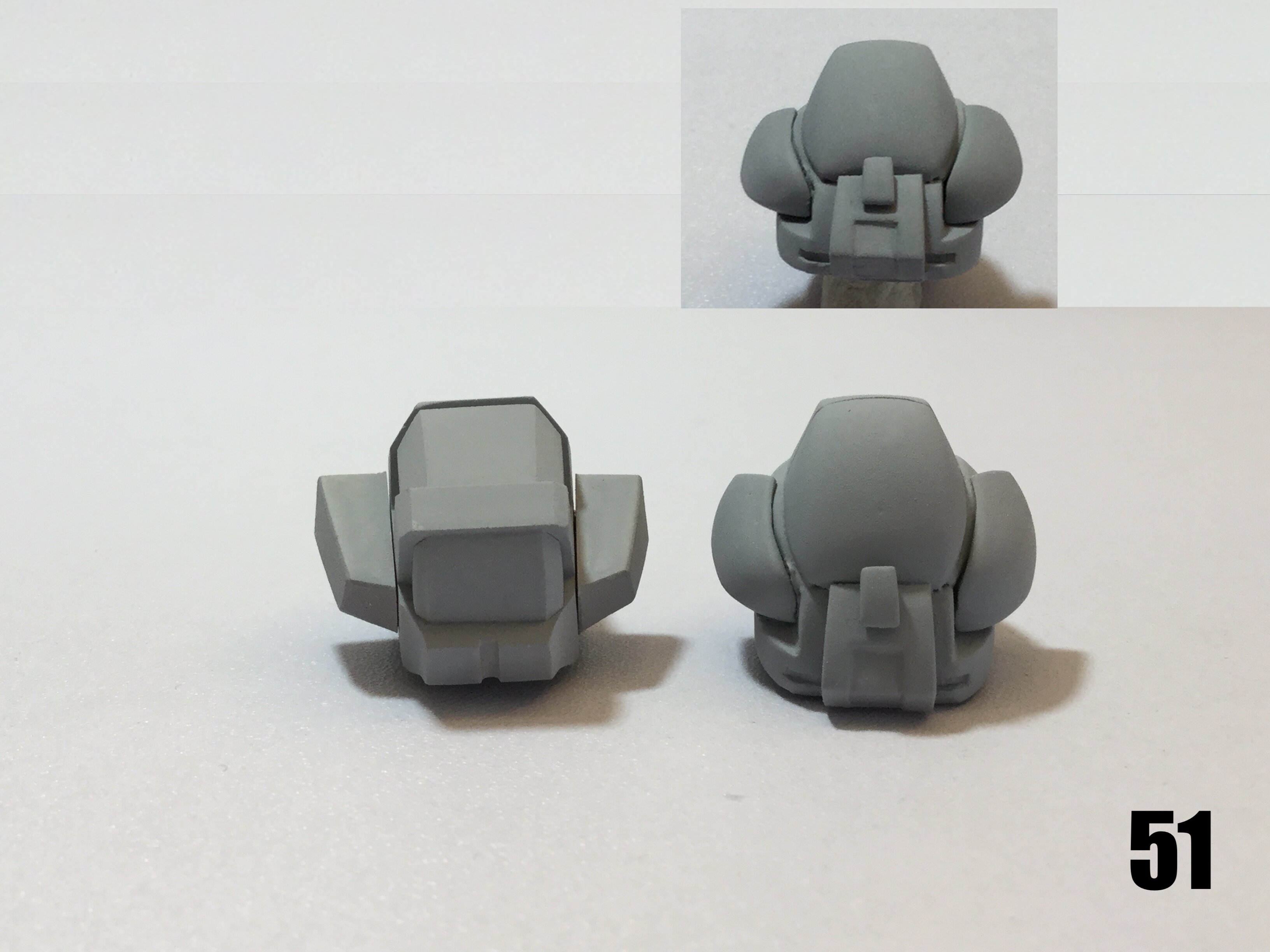
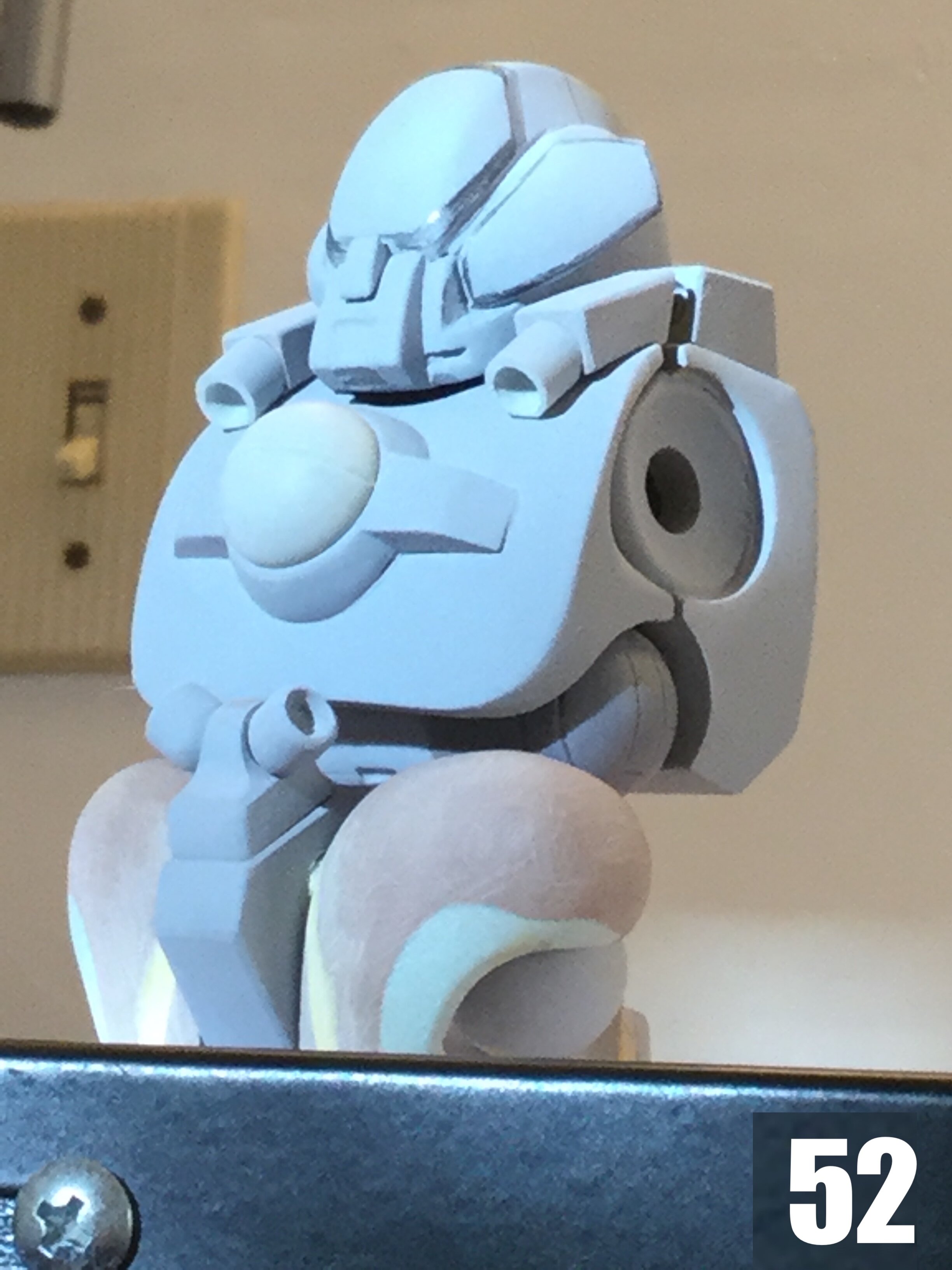
Captain's addendum: Monday, February 15th. I went back and did some corrections to the heads, as well as finish-up the cockpit area. In pics 46-47B, you can now see that the head tapers toward the front, and then narrows down more at the chin. The latter has also been flattened and made taller vertically. The tabs on either side of the medallion were also tapered at the outer edges to allow the hoses to sit more snugly to the chest. In pics 48-50, you have the details of the open cockpit. This was a significant challenge as well, because the artist is/was a perspective retard, but I think I was pretty successful at getting all the basic details. The one downside to this is that the chest plate innards will have to be Dremeled/shaved-down in order to close the cockpit. Please forgive the fact that the head sits so high and the incorrect tilt angle: the parts are very fragile and I don’t want to break the masters before they get molded. Pics 51 & 52 show the revised BUG FACE head which harmonizes not only the line-art, but also the L&S prototype images. In pic 52 particularly, you see how with very even lighting, the otherwise curvy surfaces look flat and better mimmic the 3/4 line-art view. Now that I’ve made all these changes, I need to go wet-sand all the imperfections out before I go to mold-prep.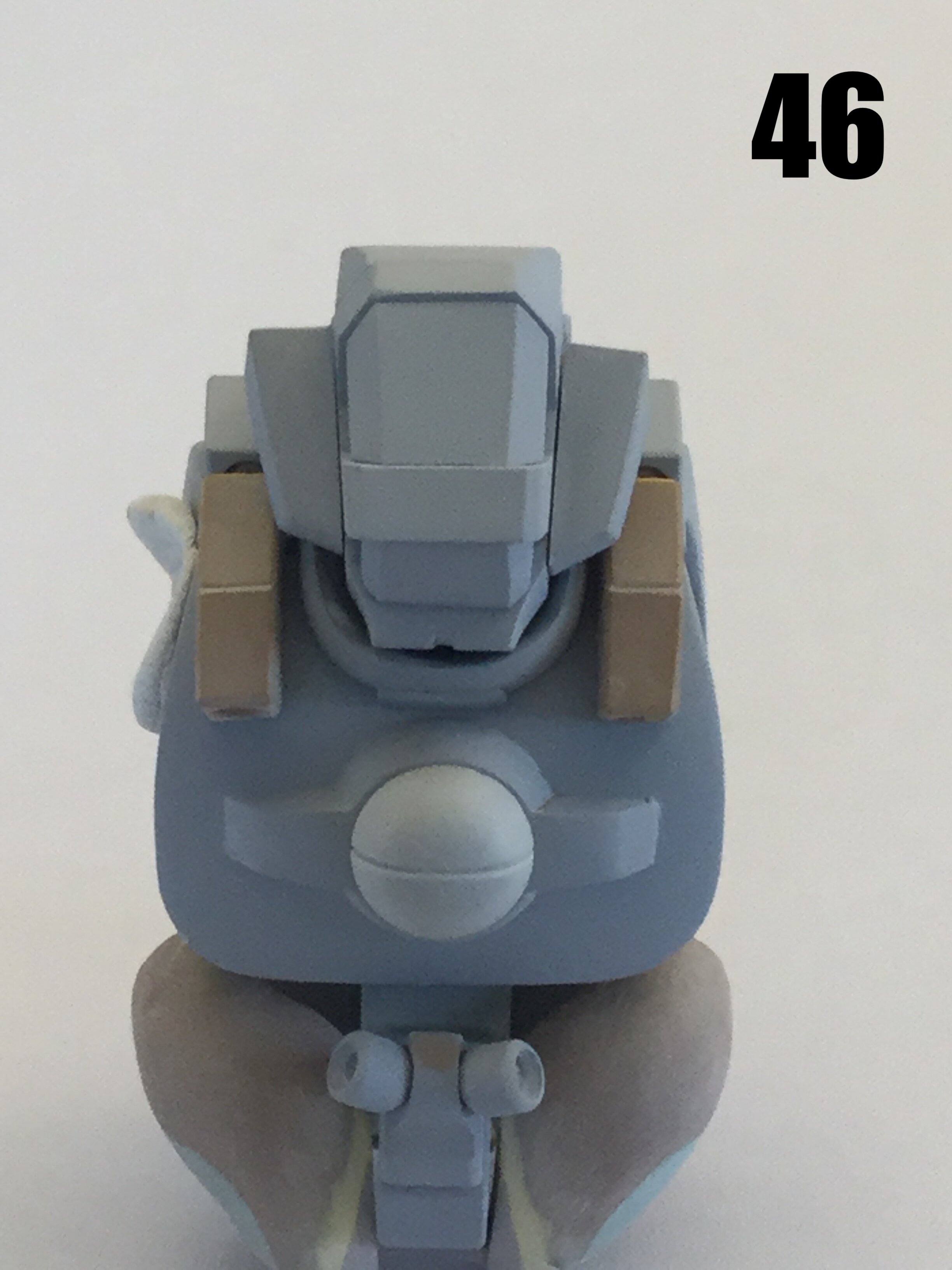

- 150 replies
-
- 1
-
-
- southern cross
- robotech
- (and 4 more)
-
1/48 SOUTHERN CROSS BIOROID PART II
captain america replied to captain america's topic in Anime or Science Fiction
Constructive criticism is helpful on wonky projects like these. The drawback to not having an art director on some projects is that you stare at your own work for so long that you lose perspective, so it's nice to have an extra set of eyeballs. Other times, the source material just doesn't make sense and I have to take a decision to make it work in physical form. -
1/48 SOUTHERN CROSS BIOROID PART II
captain america replied to captain america's topic in Anime or Science Fiction
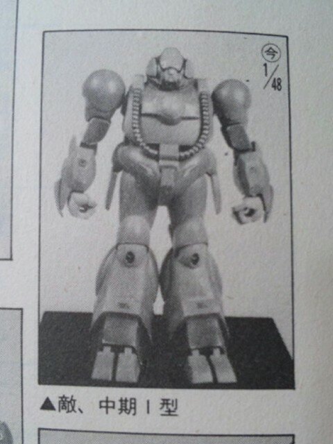
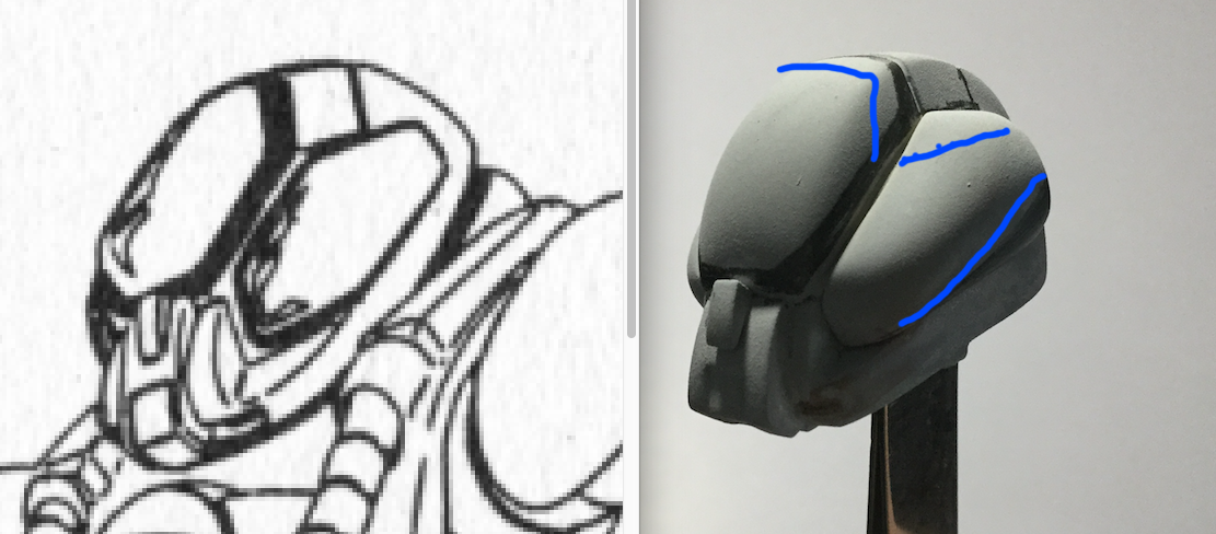
I already made some of the suggested changes to the Hemorroid head. I tapered it toward the front, narrowed the chin and flattened the end. I also relaxed the curve on the frontal lens, and it does look better--thank you for that suggestion. Hoses: they won't protrude nearly that much when bent properly and everything is glued. If you want a tip for making flexible hoses bend and hold a position, try this: put some grease on a sewing needle and carefully poke it through the length of the hose, then insert a straightened paper clip and adjust as needed. Bug Face head: better still than the animation, look at the L&S prototype in 1/48. They doubtless had the missing view at their disposal (and likely a few more) needed to render that abomination in three dimensions. If you look at the head, it actually does have that distinct, three-mound shape when viewed from the front, which I was able to achieve with a little strategic sanding. I'll show you the results of my alterations next week.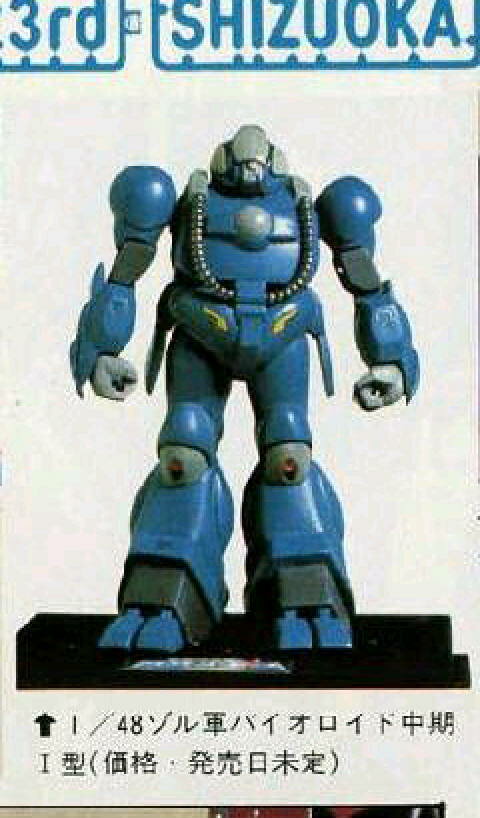
- 150 replies
-
- 1
-
-
- southern cross
- robotech
- (and 4 more)
-
1/48 SOUTHERN CROSS BIOROID PART II
captain america replied to captain america's topic in Anime or Science Fiction
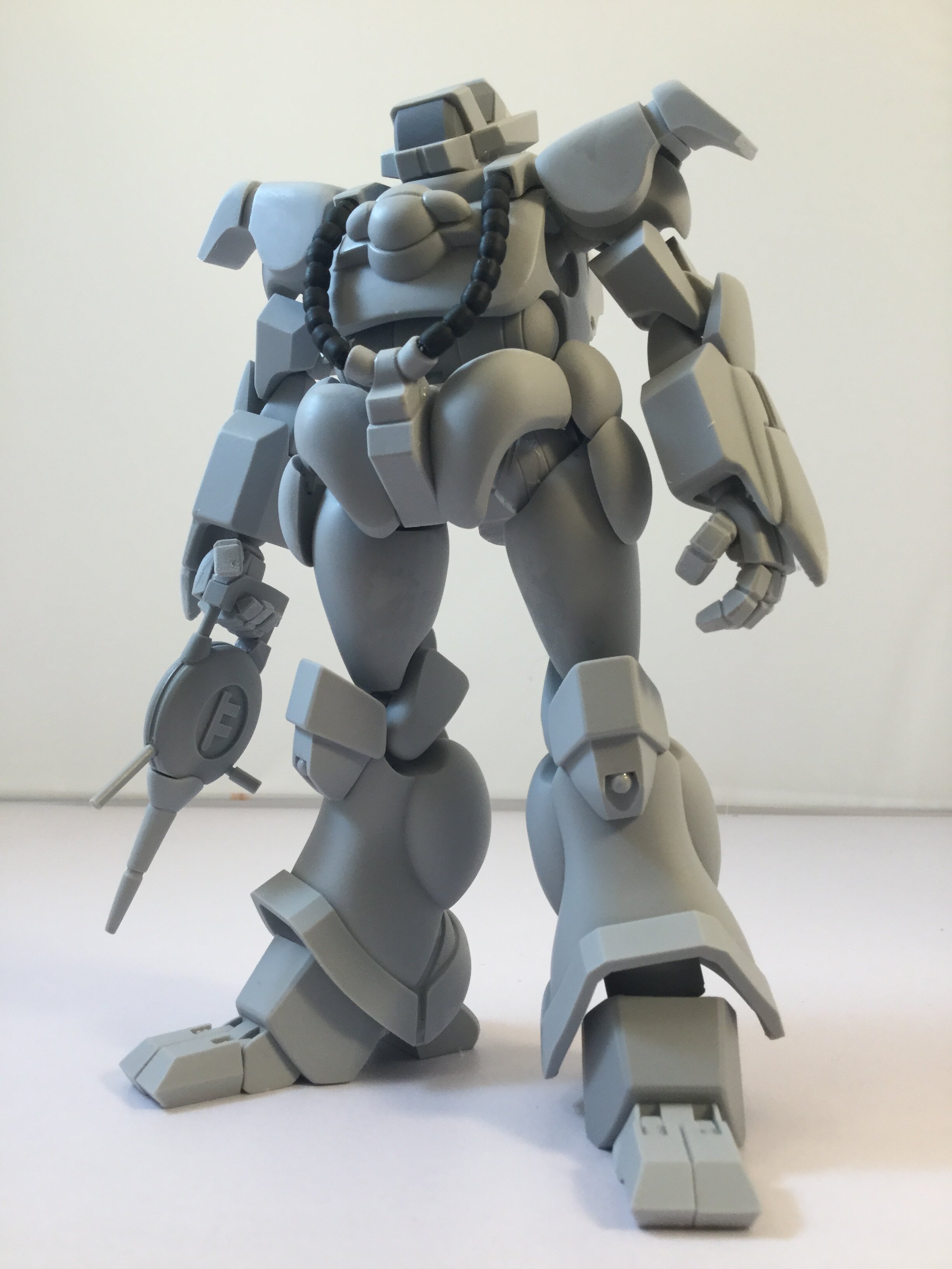
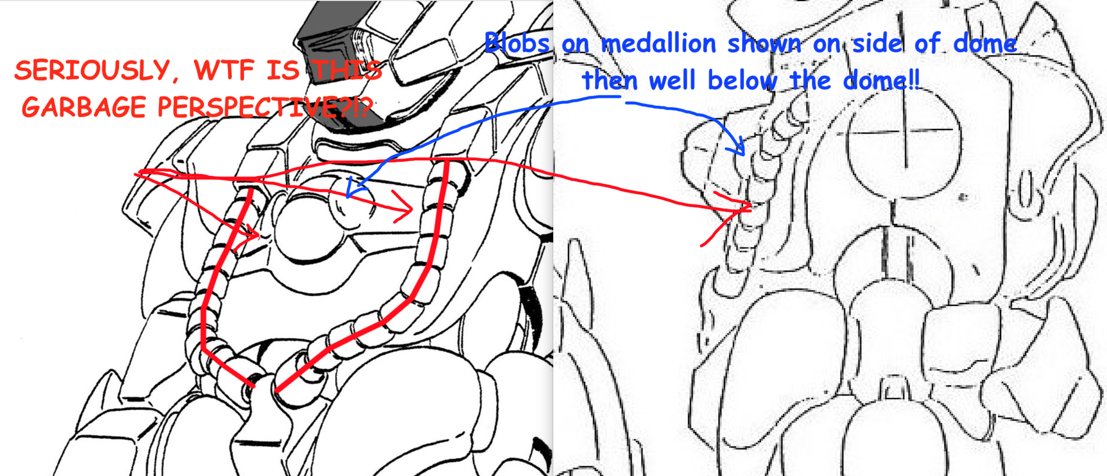
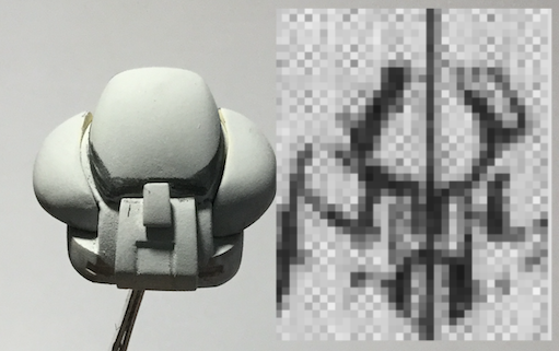
I agree with you on the Biopsycher head, and how it should taper more toward the front. The line-art shows that taper to be very slight, which I interpreted as wonky perspective, but I can remedy that. As per your own cues, I stick to that as a primary reference because,and as you've stated yourself, the animation is all over the place with regards to proportions, sizes and colors. When I said that this thing is/was a perspective nightmare, I meant it: things are drawn in ways that are simply absurd, nevermind the fact that different views don't lign-up with each other, they often depart from physical reality altogether. You'll also notice that the yellow-orange rectangular tube covers on the shoulders appear big and beefy in some views, and less prominent in others. That difference alters the way they interact with the head. One of the nicer (if not one of the nicest) animation renderings of it shows the head to be very wide indeed, so choices have to be made. Now on to the hoses on the chest. You have to bear in mind that the hoses are currently rigid resin masters, so they will not drape as nicely as flexible units, which will be in the kit. Also, given the shown thickness of the medallion's lateral tabs, the line-art and the animation don't seem to take that topography into account when drawing the hoses. In fact, look at the way the medallion housing denotes a convexity to the chest, then the line-art below acts like those tabs aren't even there to alter the course of those hoses, which would have to be deflected outward/forward, over the tabs. As for Bug Face, that head was its own mini perspective nightmare, as some lines shown in the 3/4 front and rear view can't converge the way they do in the line-art, which in turn alters the way the side-blobs contour the head. Truth-be-told, I actually prefer my rendition of it... And yet. I see room for improvement, but it's not as far off as you think. I ws able to blow-up a VERY small partial frontal view of the face, and though it's quite grainy, you can see that there's a "jowliness" to it. Pretty decent, considering that all I had to work with was the 3/4 view. Taking into account the wonky perspective, I'm pretty close. Some lines need to be re-scribed and the the lateral "eyes" trimmed, and I think that will be on-point.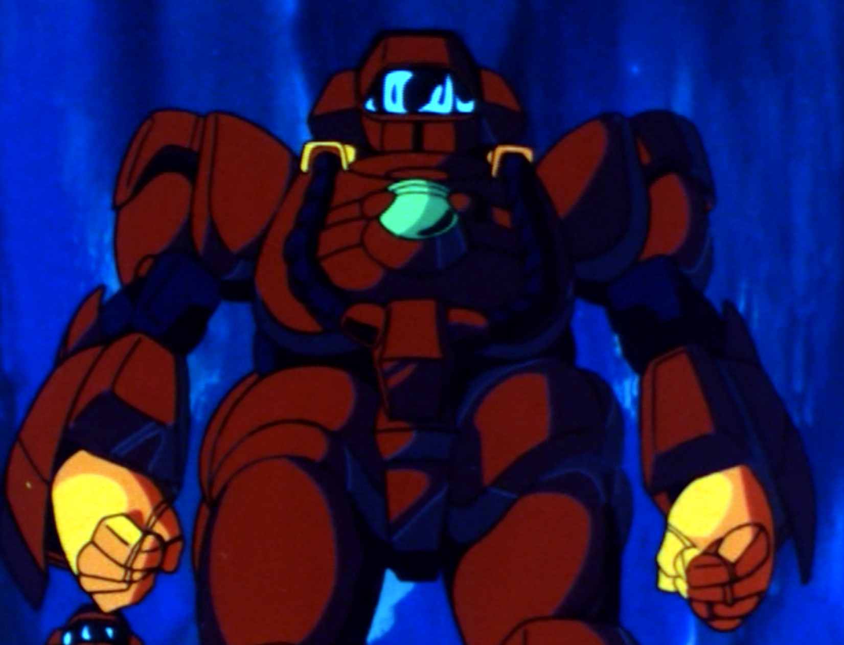
-
1/48 SOUTHERN CROSS BIOROID PART II
captain america replied to captain america's topic in Anime or Science Fiction
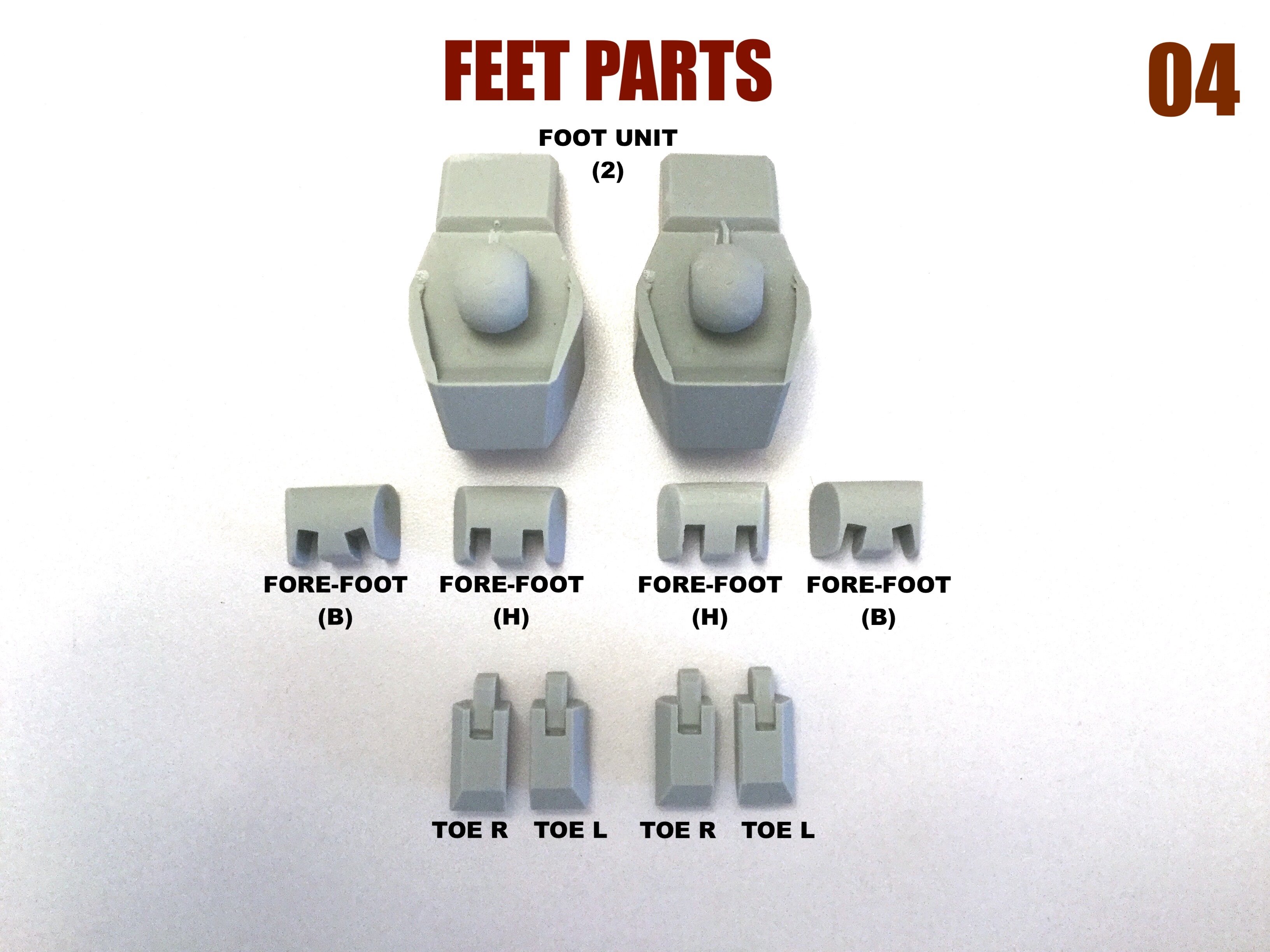
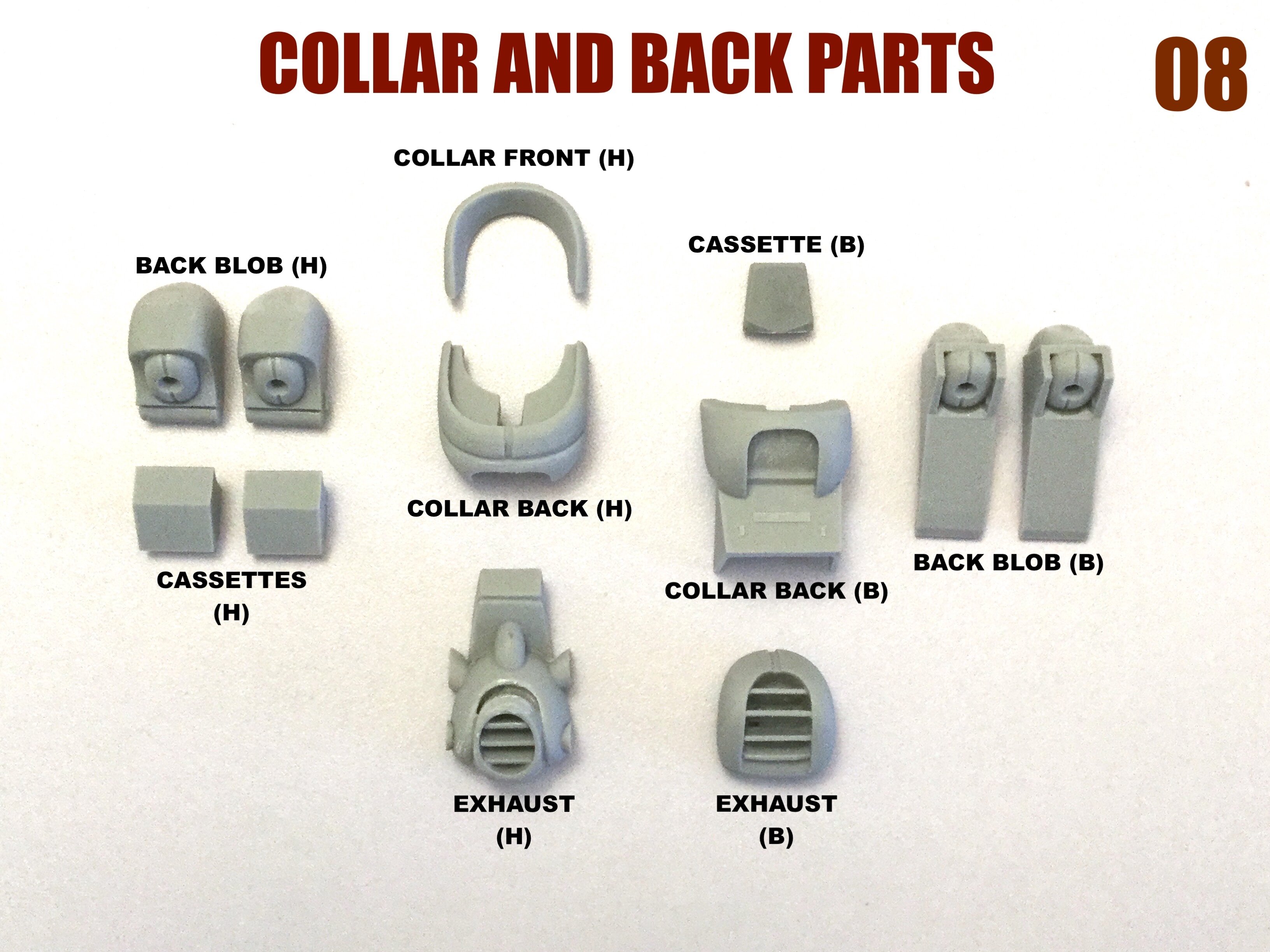
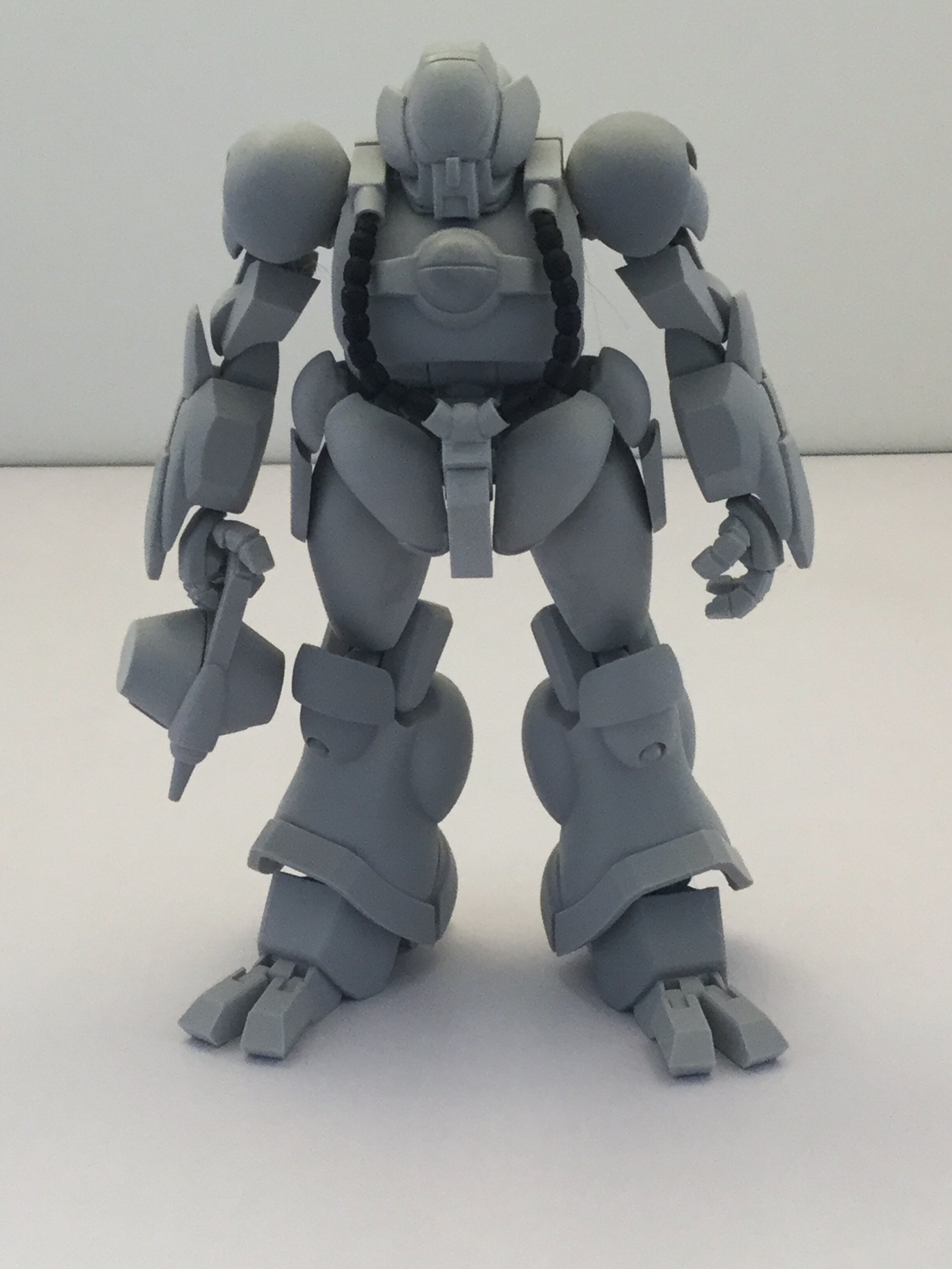
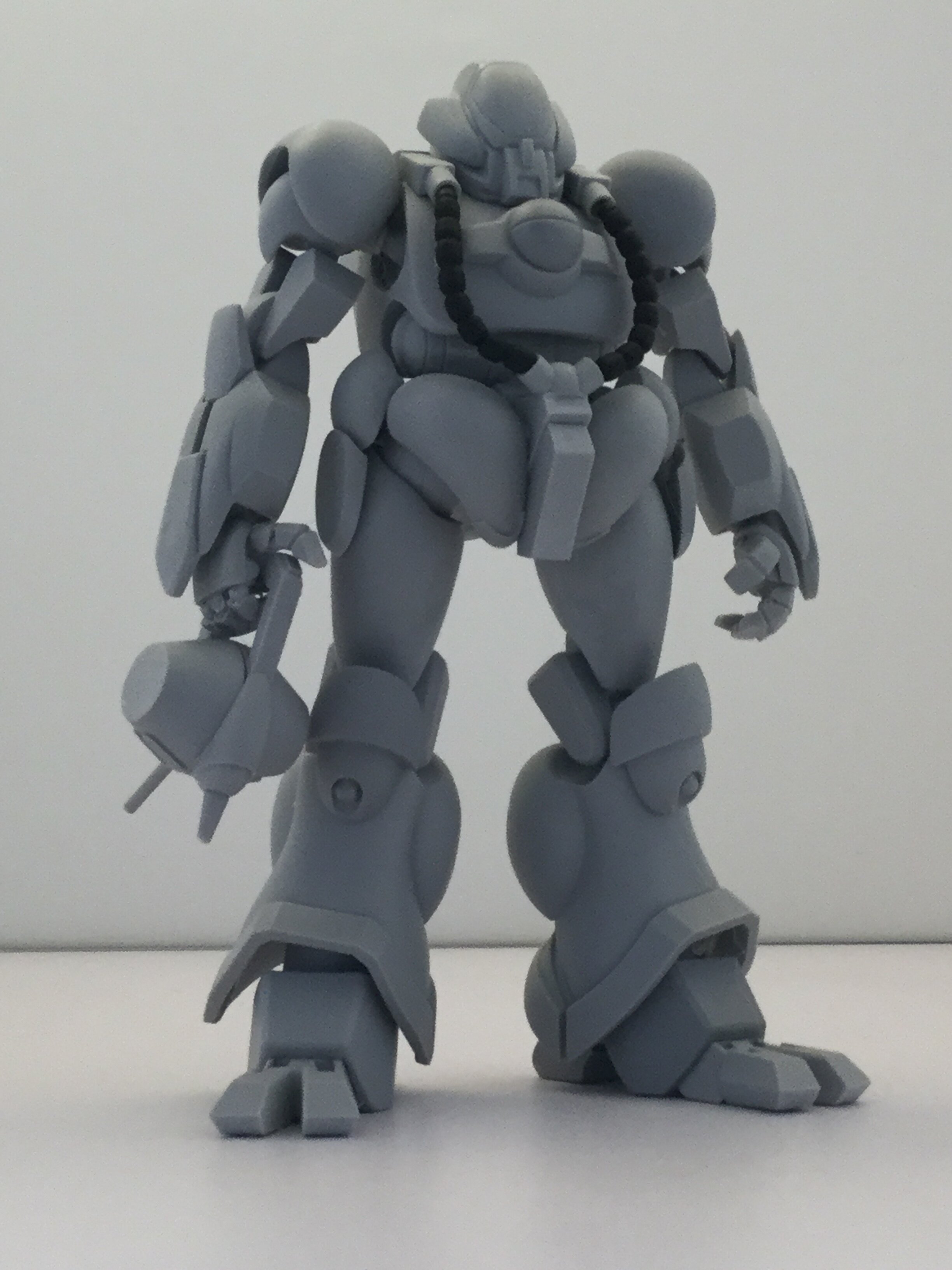
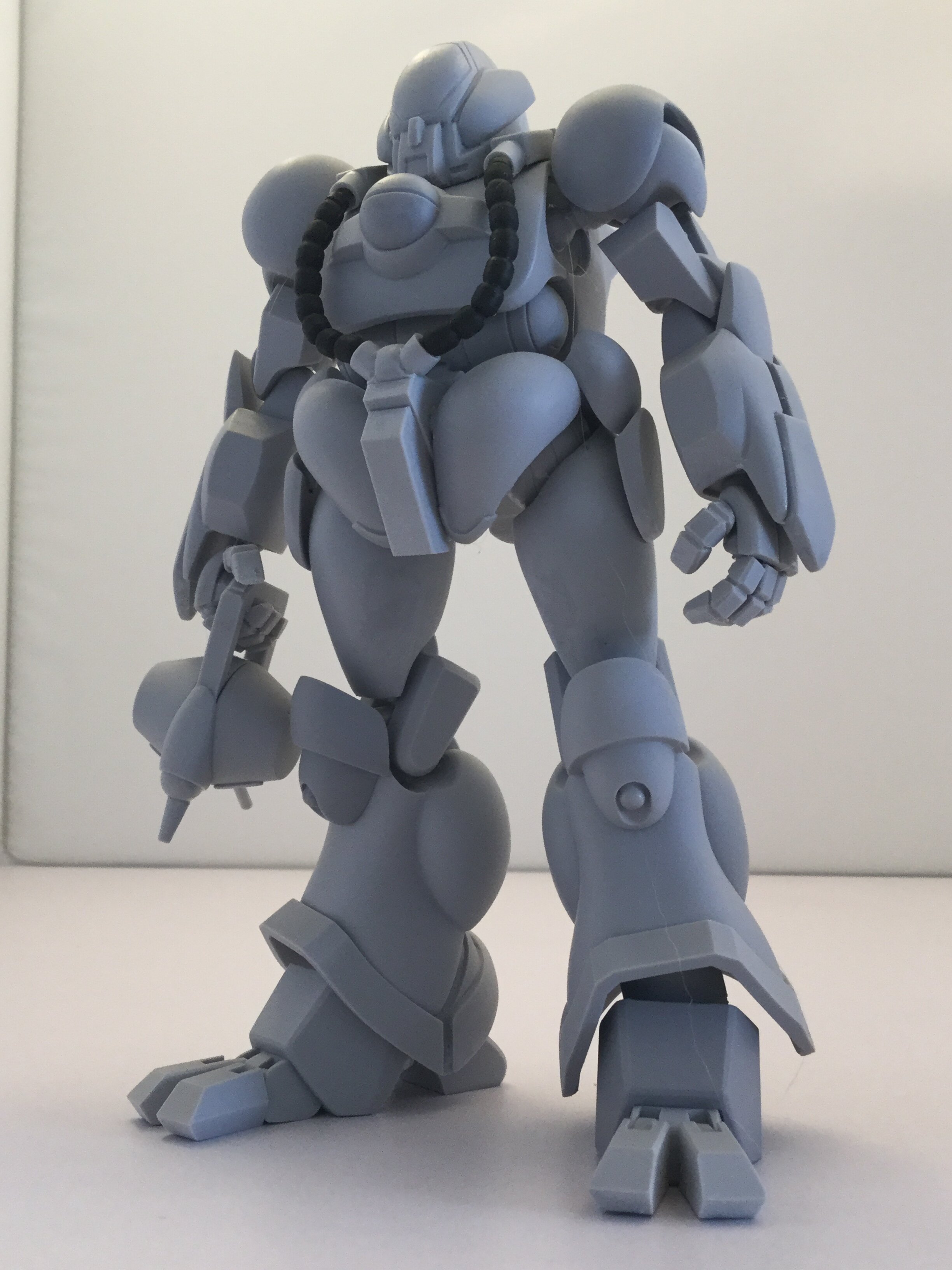
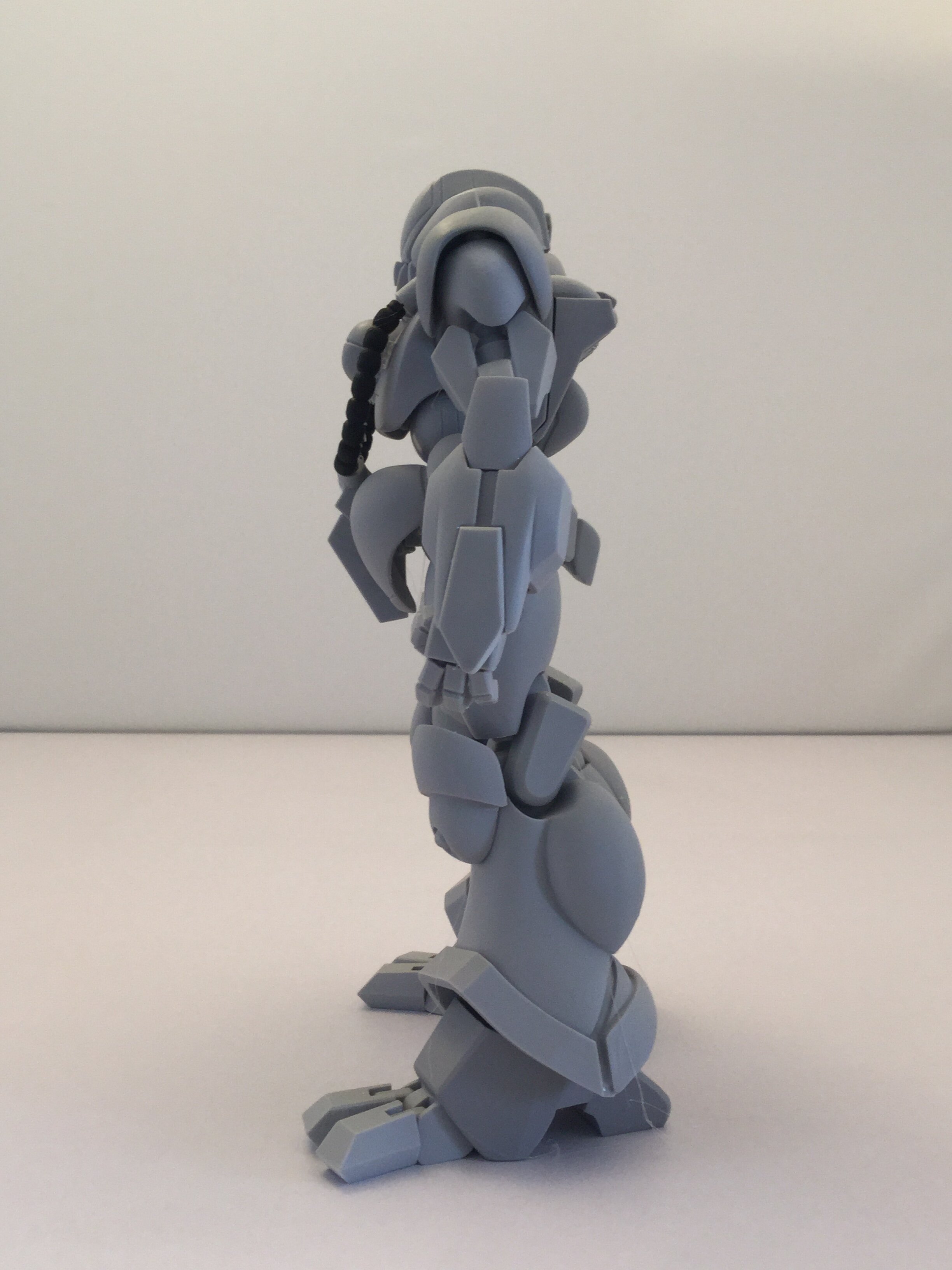
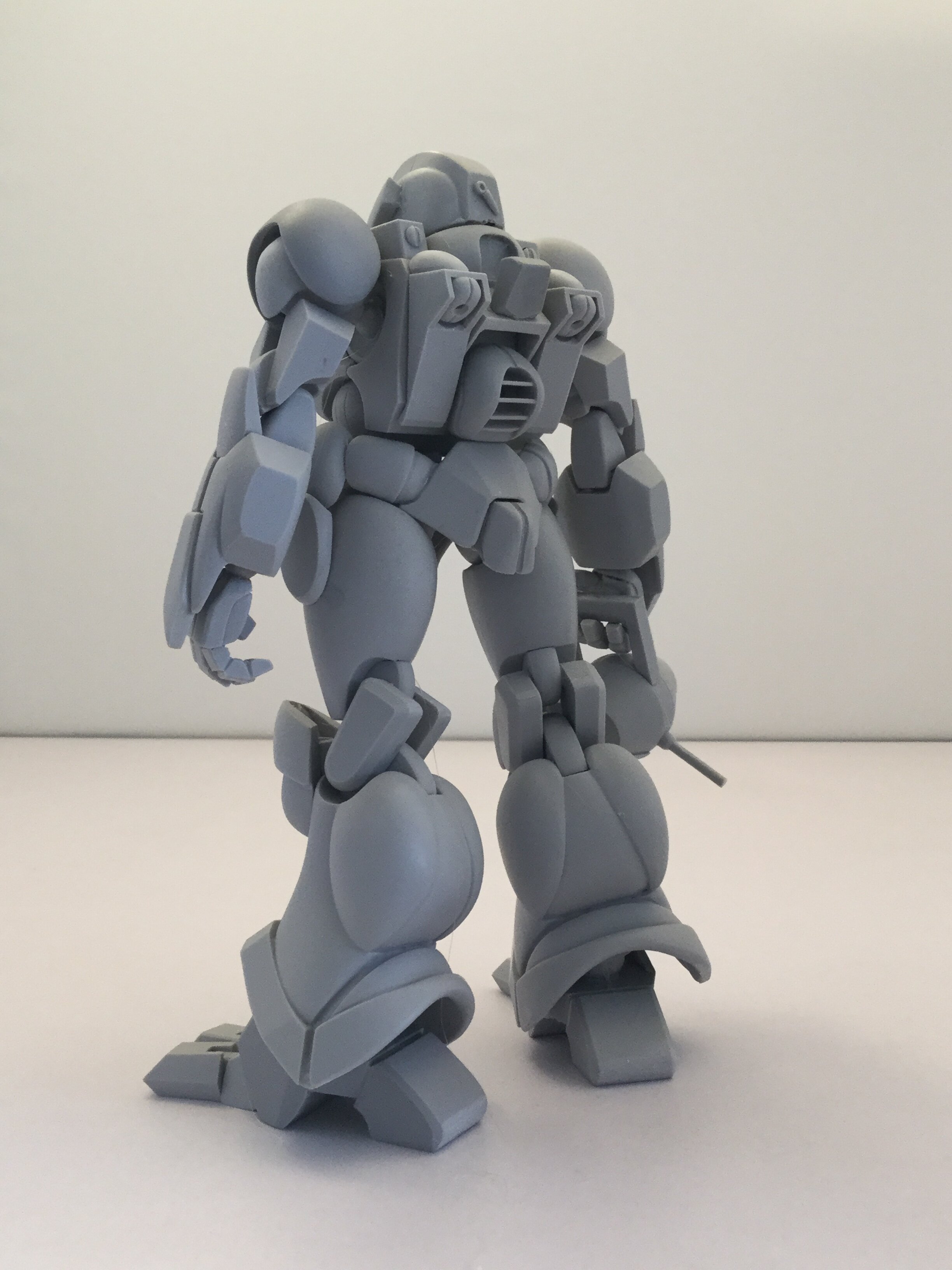
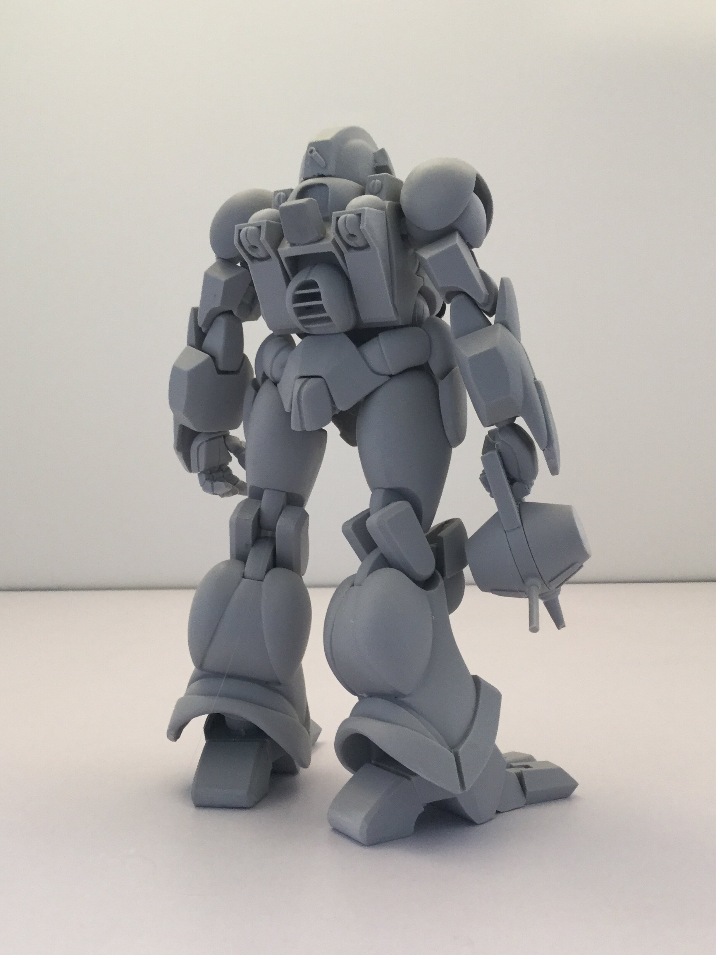
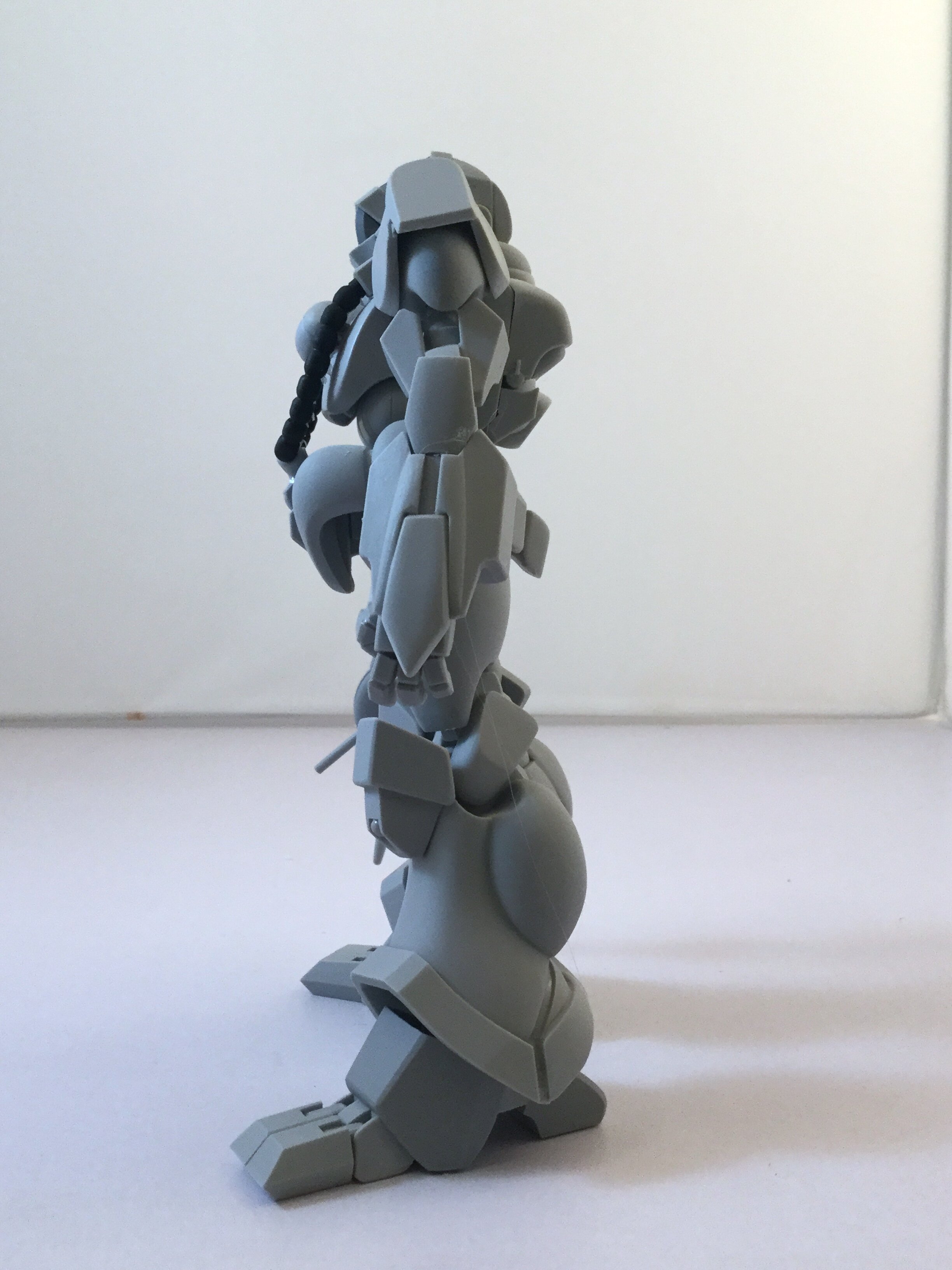
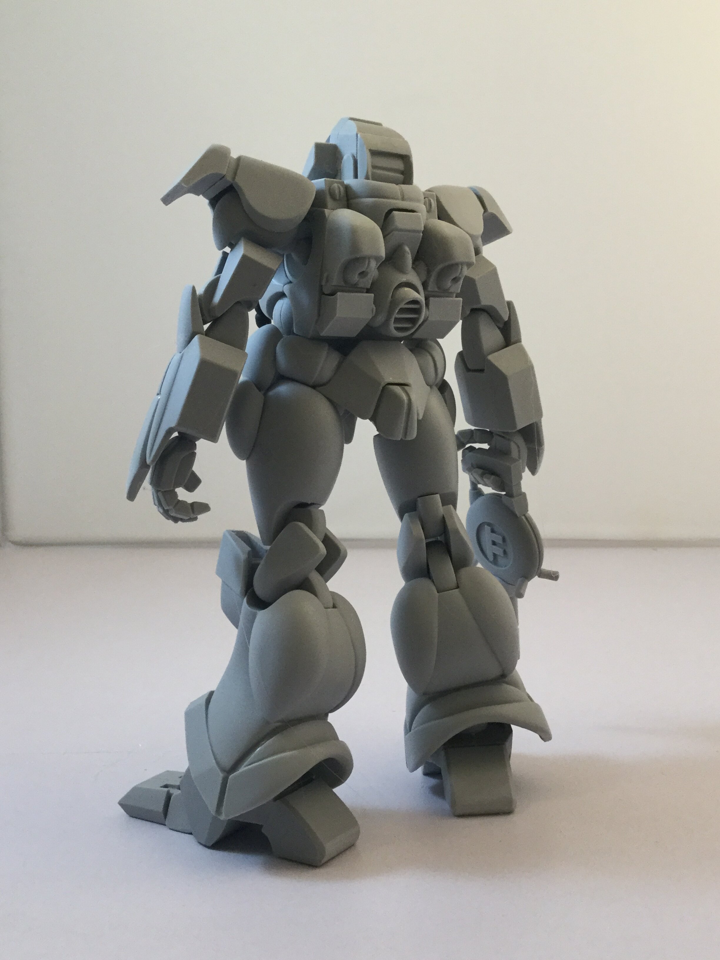
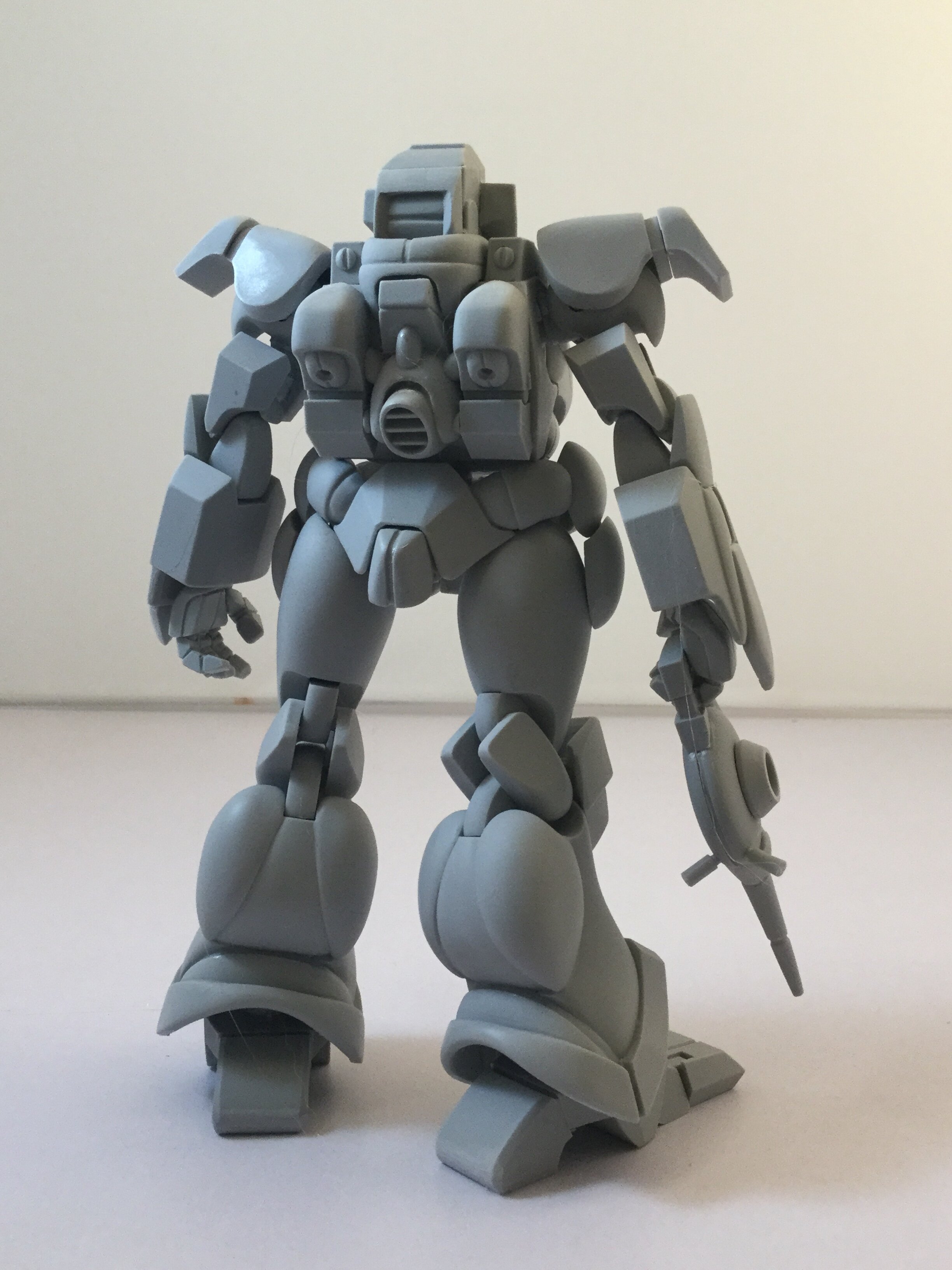
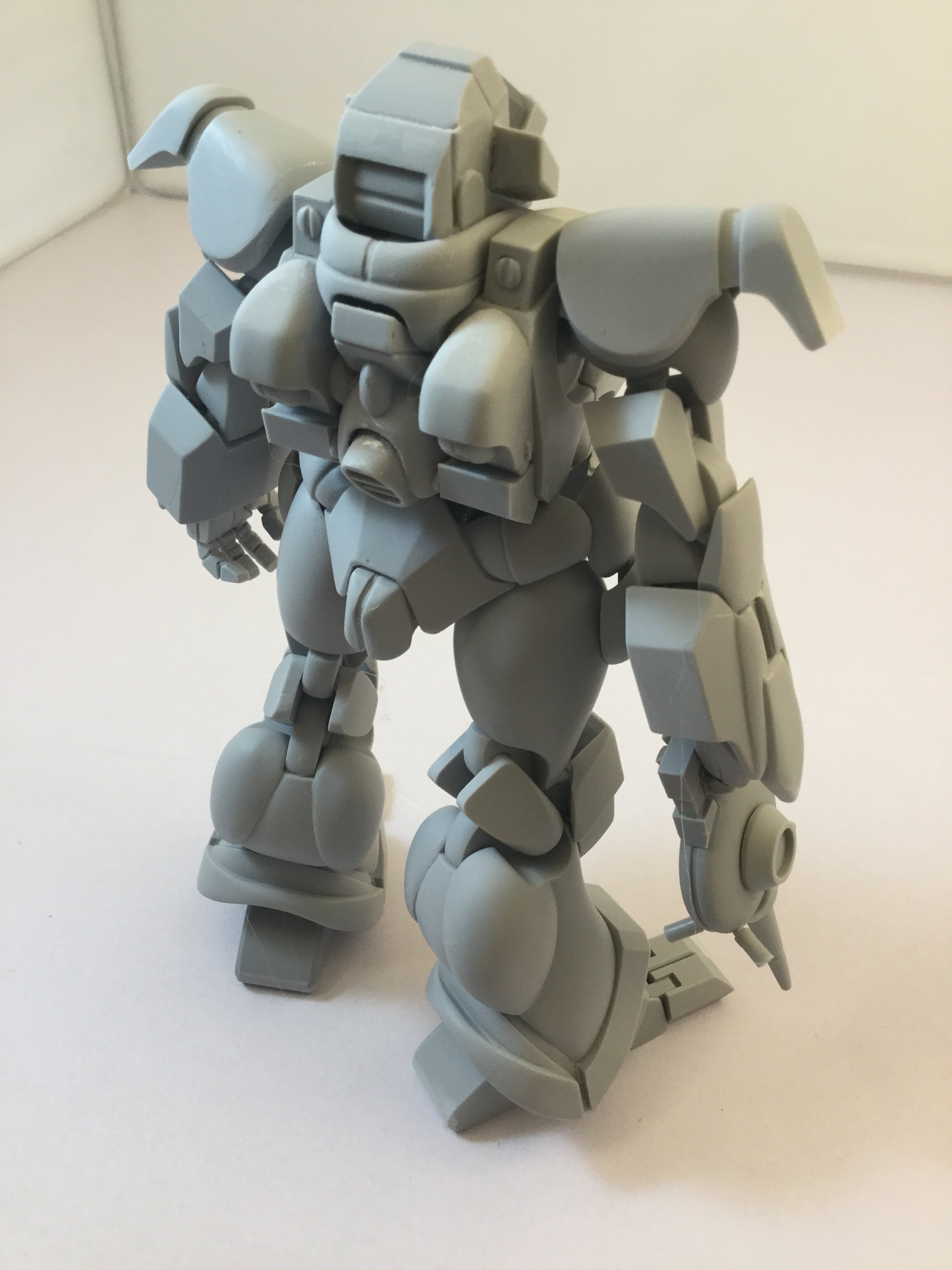
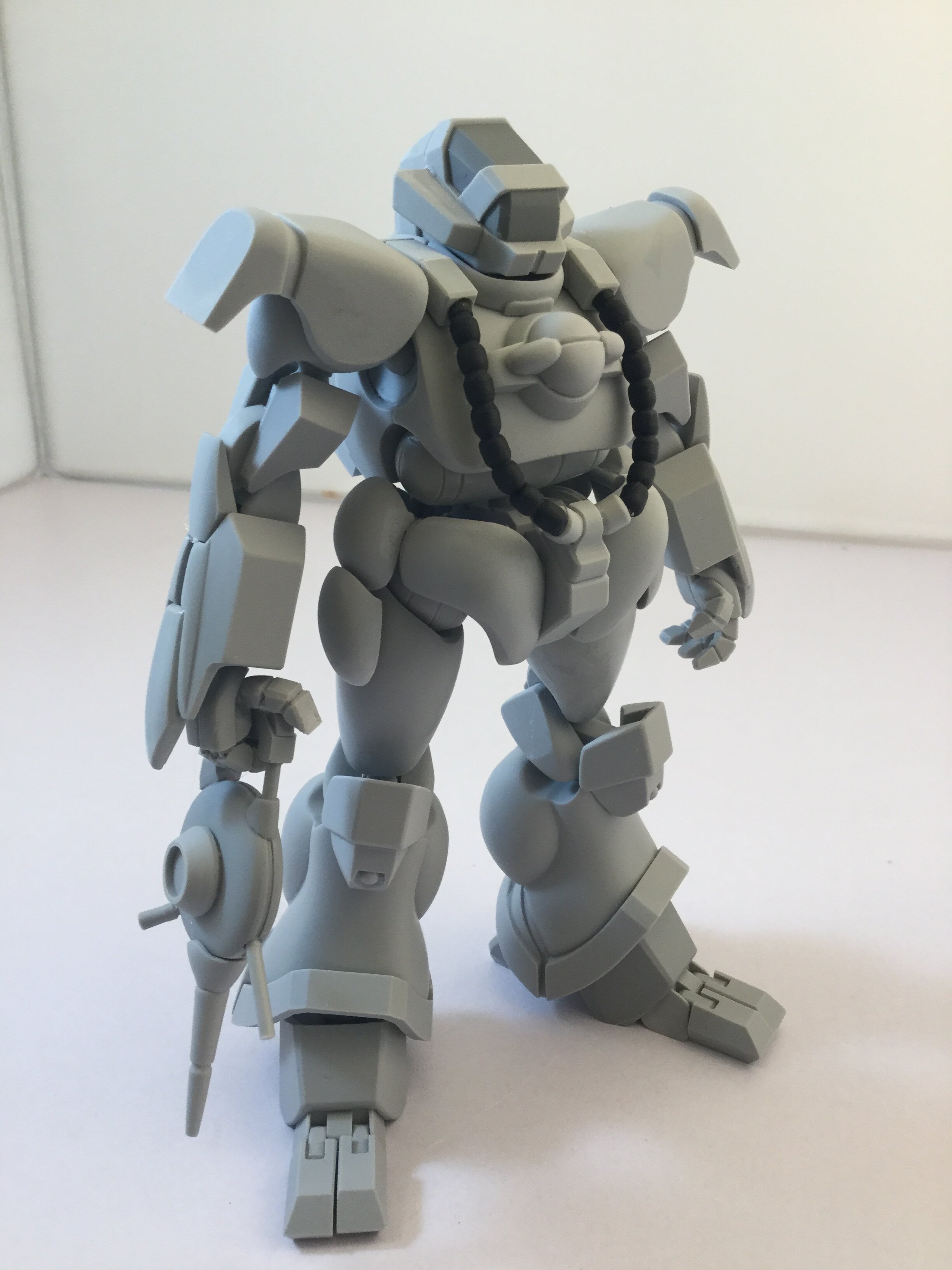
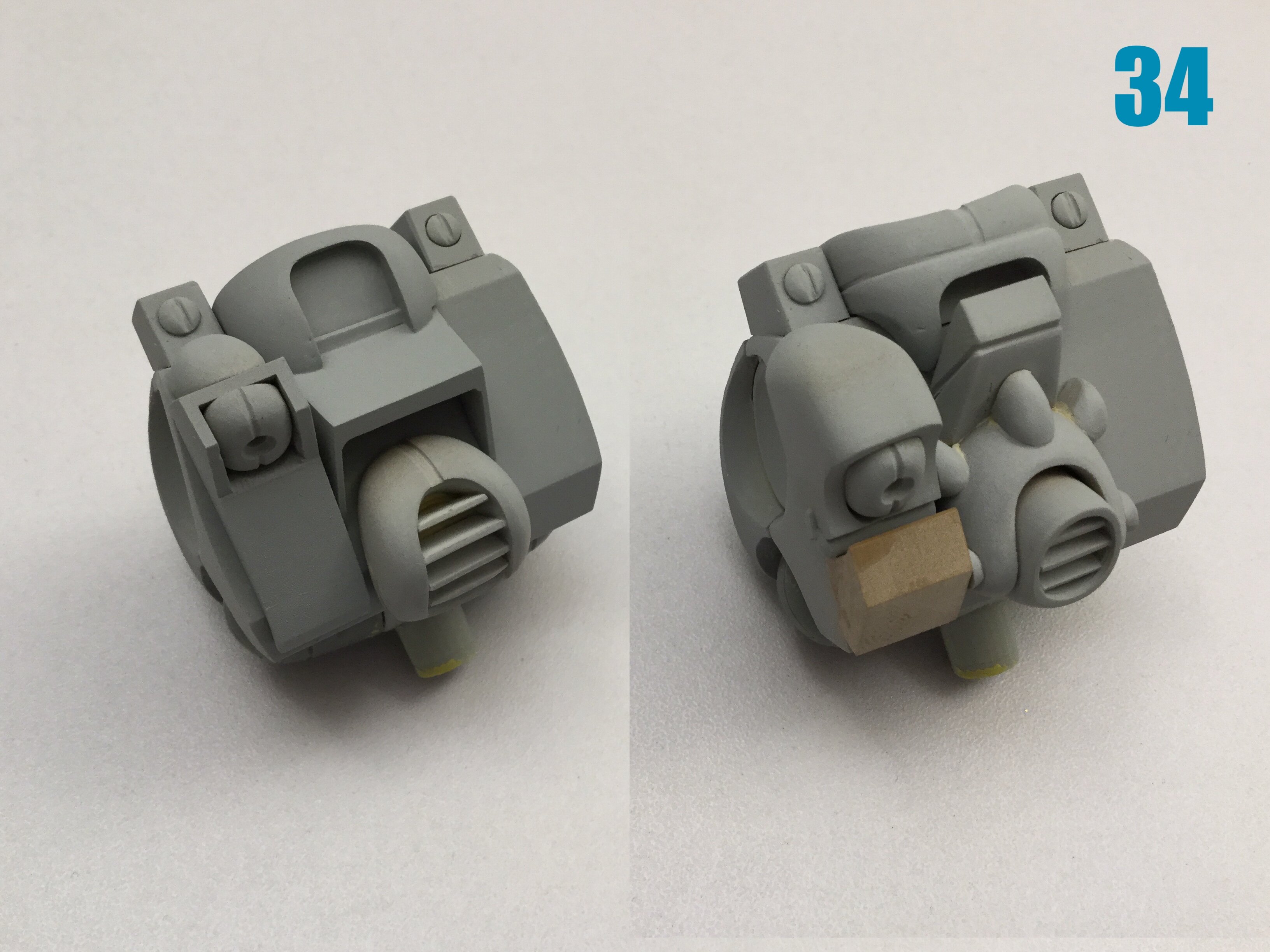
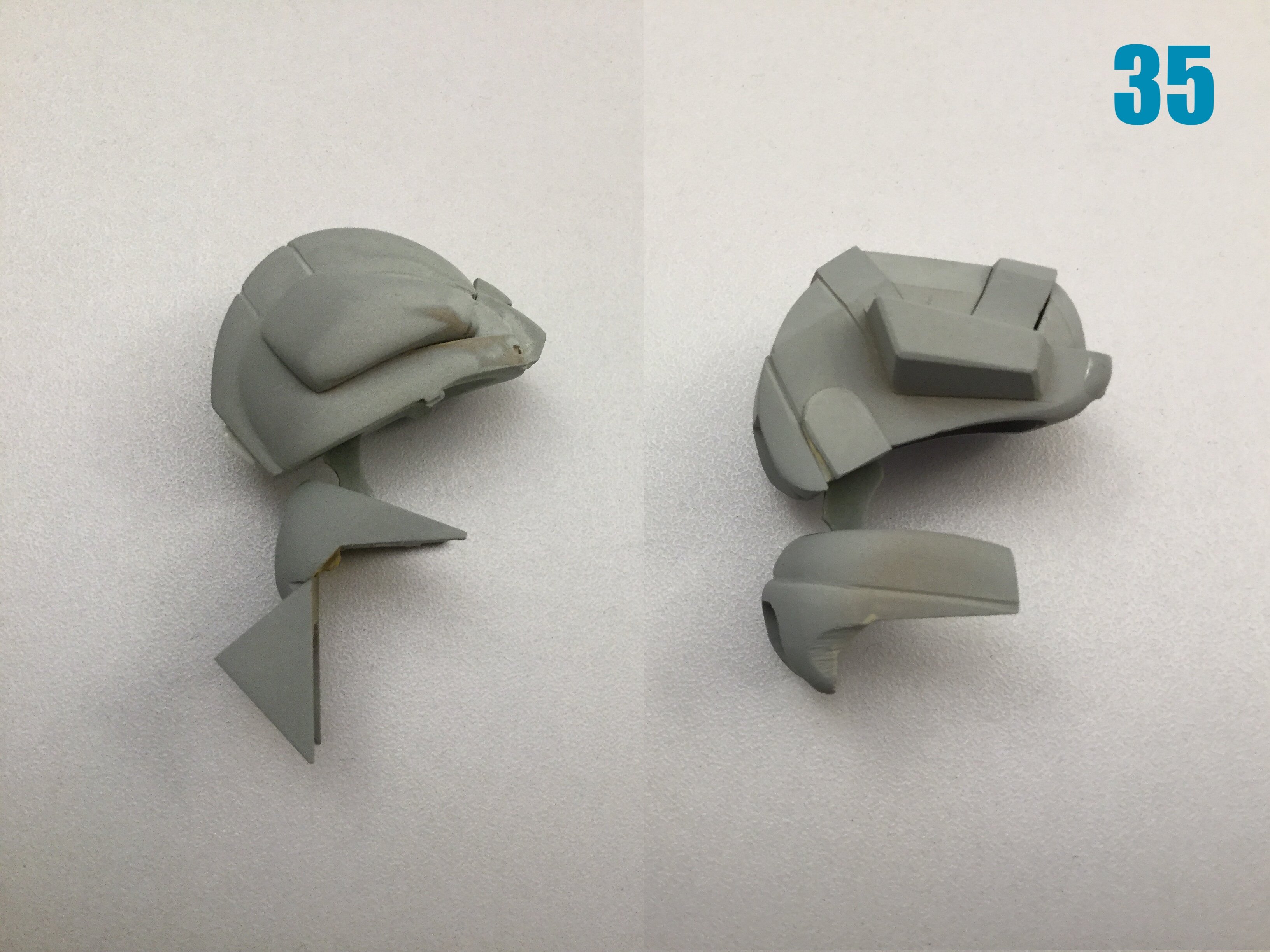
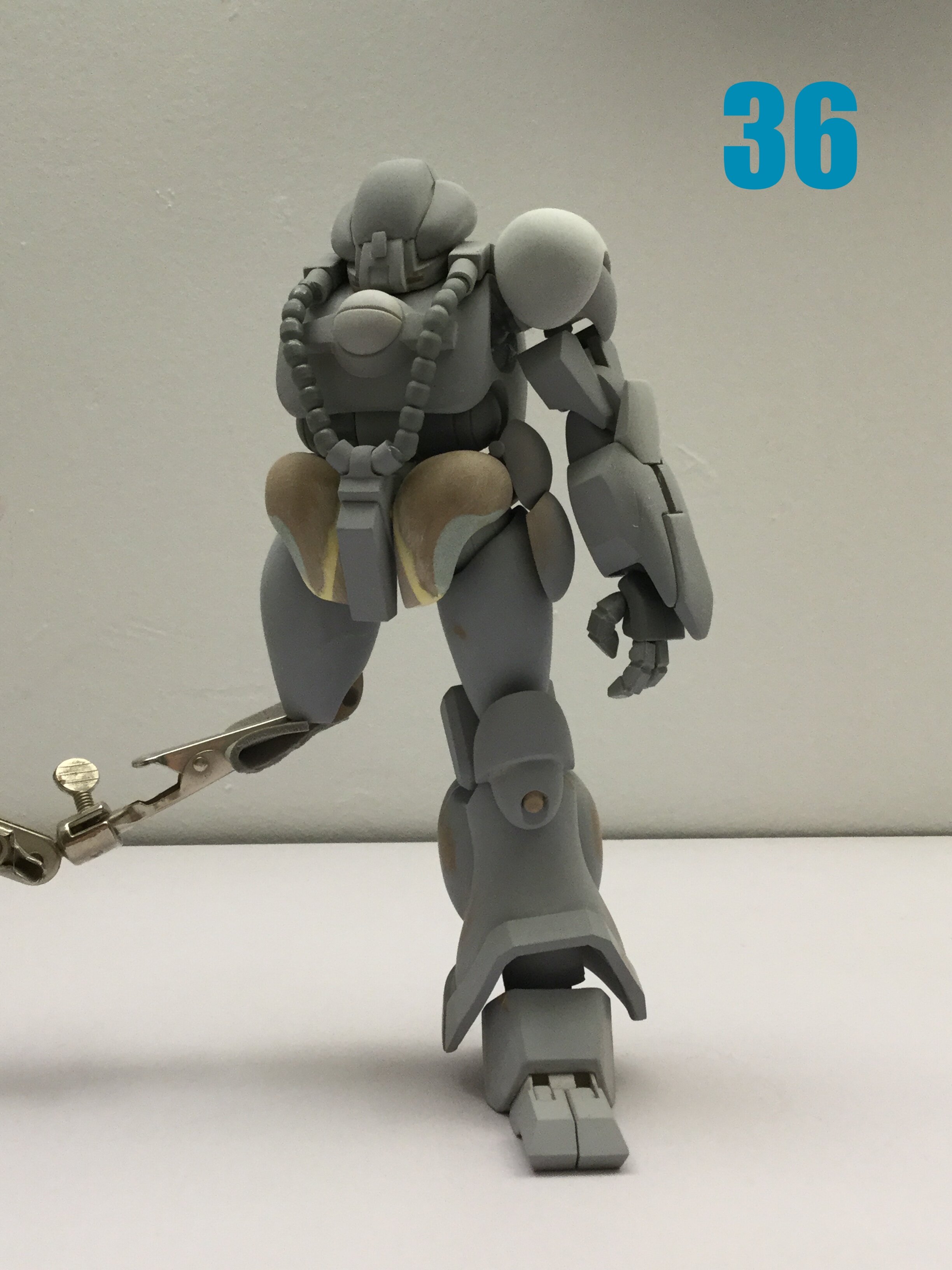
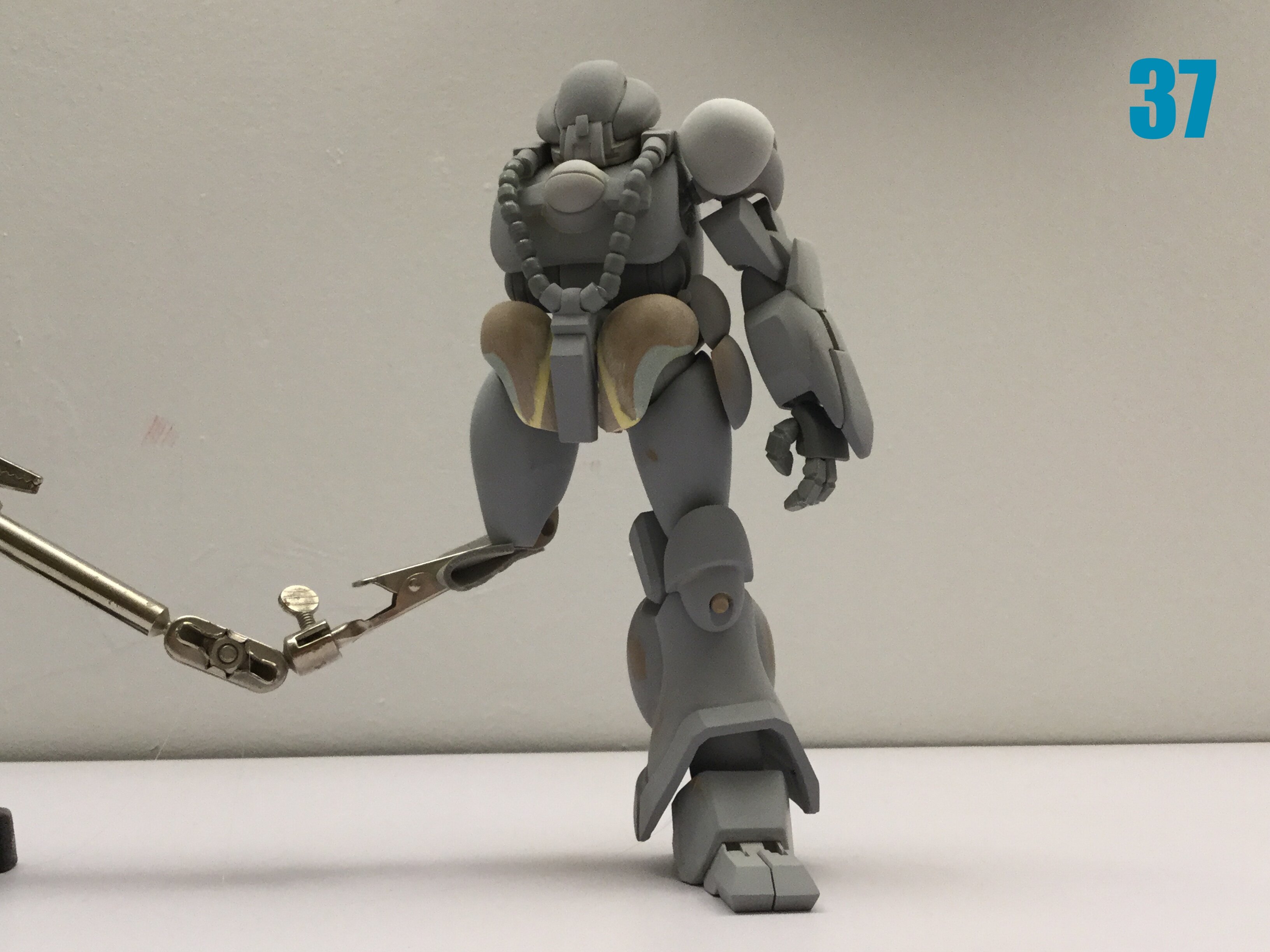
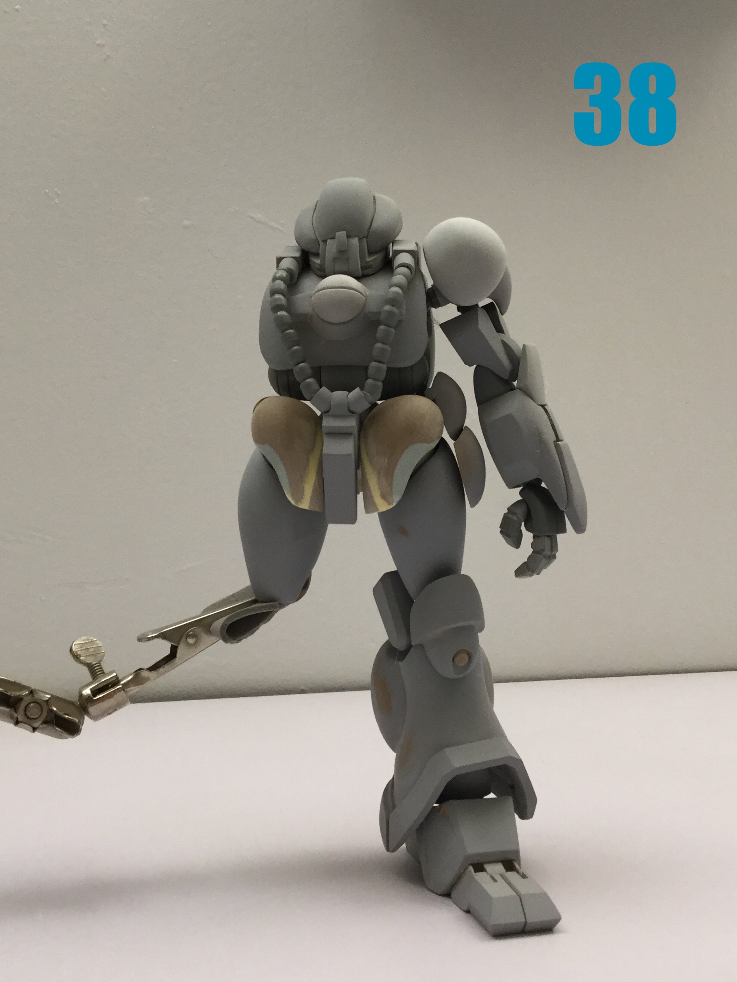
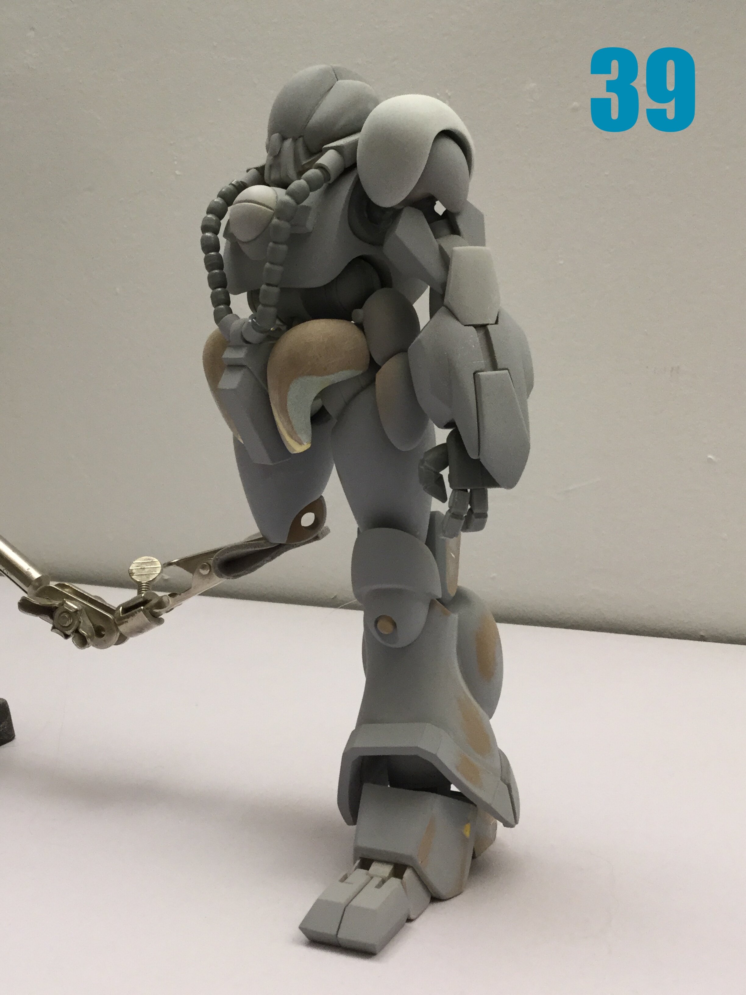
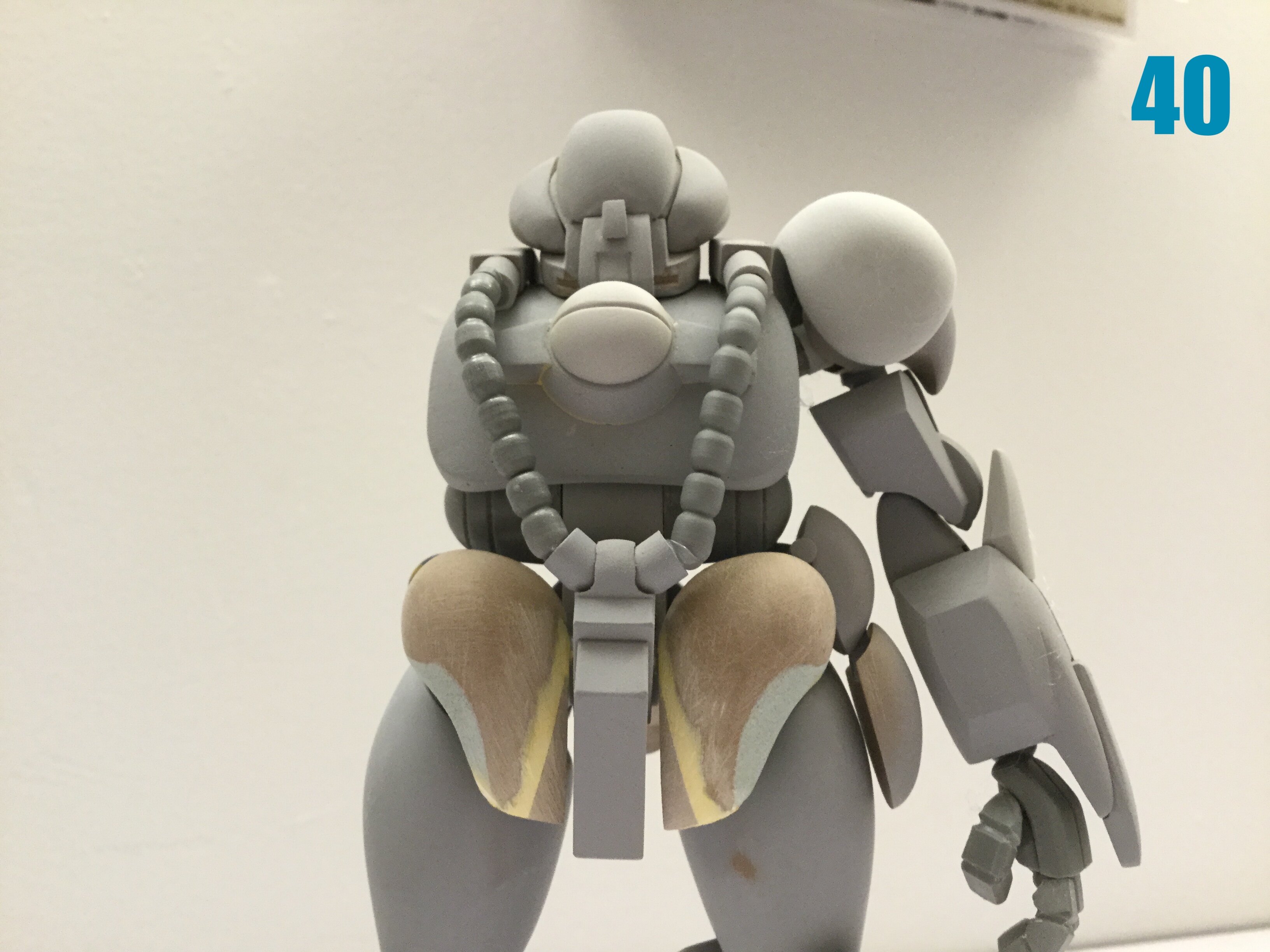
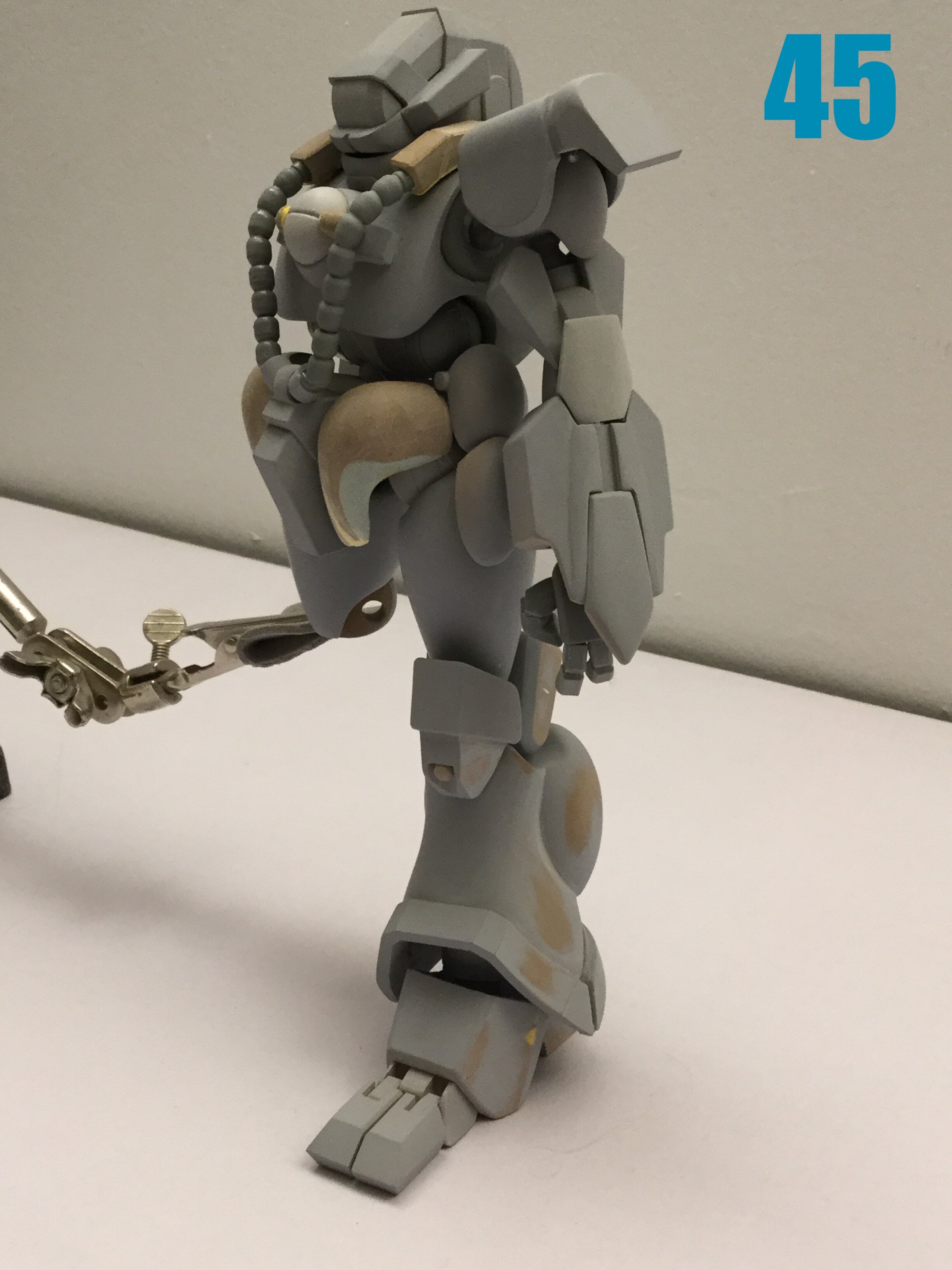
Captain’s log: Thursday, February 10th. Almost done! Pic 34 shows the (almost) complete back details for both variants. A few small details still left to add, but the differences are quite considerable; certainly more so than the differences on the three MK I variants. Pic 35 shows the flip-top head for Bug Face and Hemorroid. The « mechanism » (and I use that term loosely) shown in the line-art was a perspective exercise in frustrating madness that Franz Kafka would be envious of, so I made something more, umm… Functional. A lot of the detail saturation just looks like a mess of wires or cables, so I’ll leave it to the individual modeler to add those as they see fit. Pics 36-40: glorious Bug Face is glorious!! Please note that most parts are just tacked together so as to avoid damaging them. Final fit will be better. Also, some parts (skirts, crotch, etc.) still need to be cast and modified to suit each variant, which is why some details are a bit off. I’m also going to make an optional fore-foot that allows for the splayed toes option. Pics 41-45 show Hemorroid in all his splendor. Again, there are a few details that need to be streamlined. I will show the cockpit stuff next week, as I need to first cast some parts to finalize it. I’m positively giddy with the way the masters turned out, and while the MK I got more screen-time, I really do think that this mecha design is superior and tragically underserviced. Also, this will be the final call for pre-orders, so if you wanted in on this kit, it's now or never.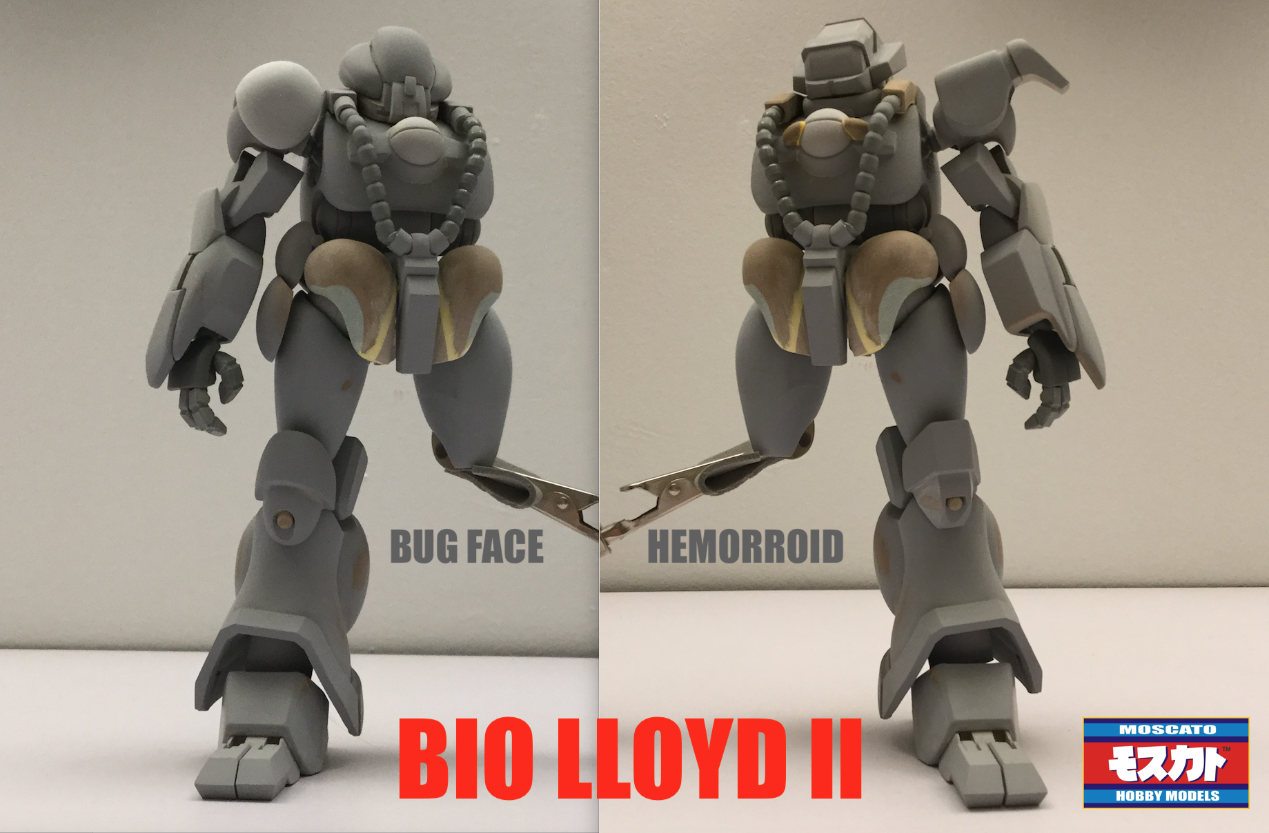
- 150 replies
-
- 1
-
-
- southern cross
- robotech
- (and 4 more)
-
1/48 SOUTHERN CROSS BIOROID PART II
captain america replied to captain america's topic in Anime or Science Fiction
Hey guys. I'm going to skip next Friday's update so that I can focus on a lot of the teeny-tiny details. The next update on Feb 11th will be more substantial. -
1/48 SOUTHERN CROSS BIOROID PART II
captain america replied to captain america's topic in Anime or Science Fiction
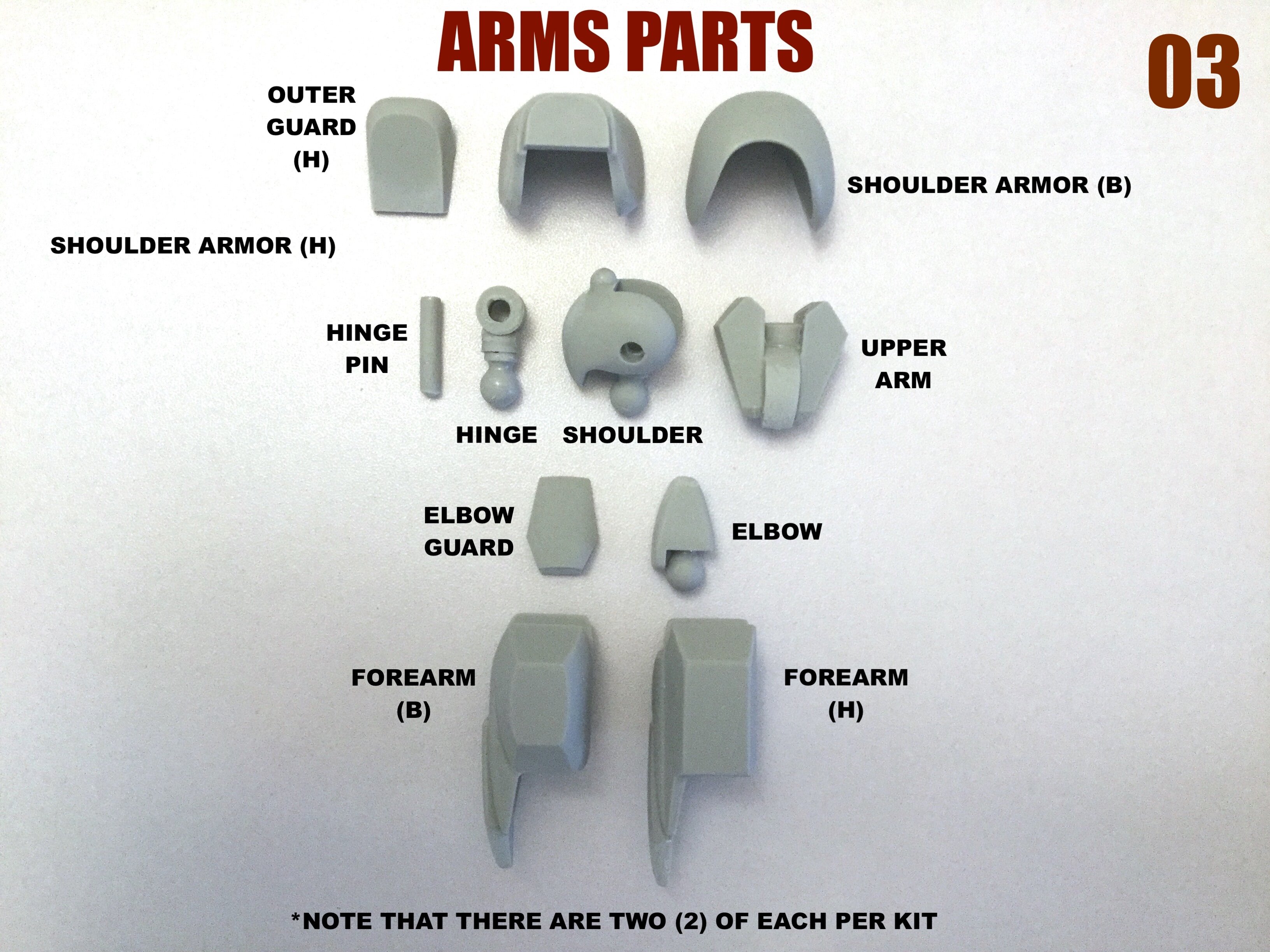
Part of that extra height was out of necessity: the extra joints needed in the arm meant that the arms themselves needed to be longer, and I didn't want Dr. Hemorroid to end up looking like a gorilla, so... Longer legs. What's odd about this design is that once you get past the Hellraiser-type perspective nightmare that is the line-art, there actually are some sensible improvements. The chest, despite not being as thick, actually affords better cockpit protection, and the mecha's mass is more centralized than on its predecessor. Aesthetically, it looks meaner and more menacing as well. -
1/48 SOUTHERN CROSS BIOROID PART II
captain america replied to captain america's topic in Anime or Science Fiction
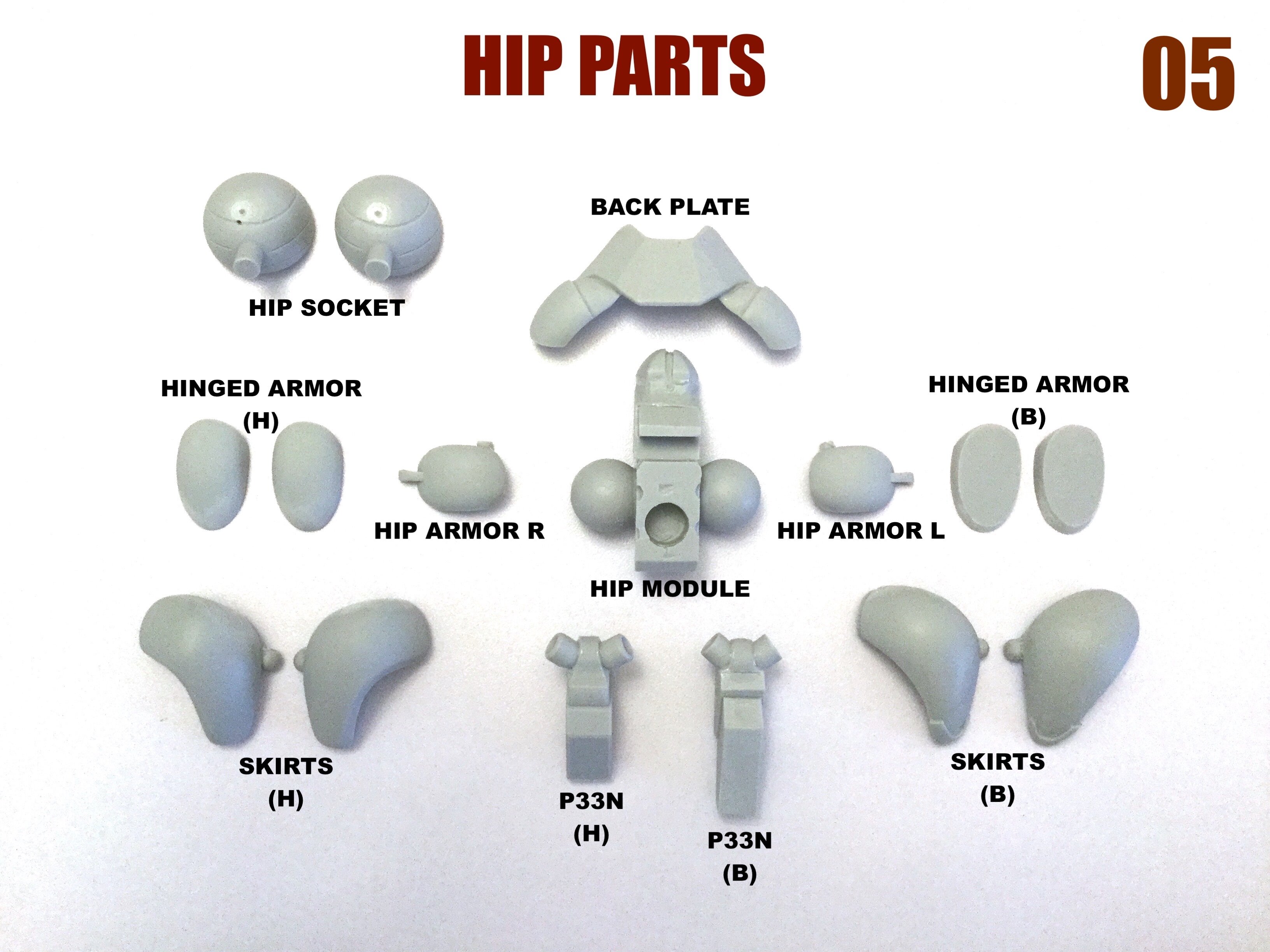
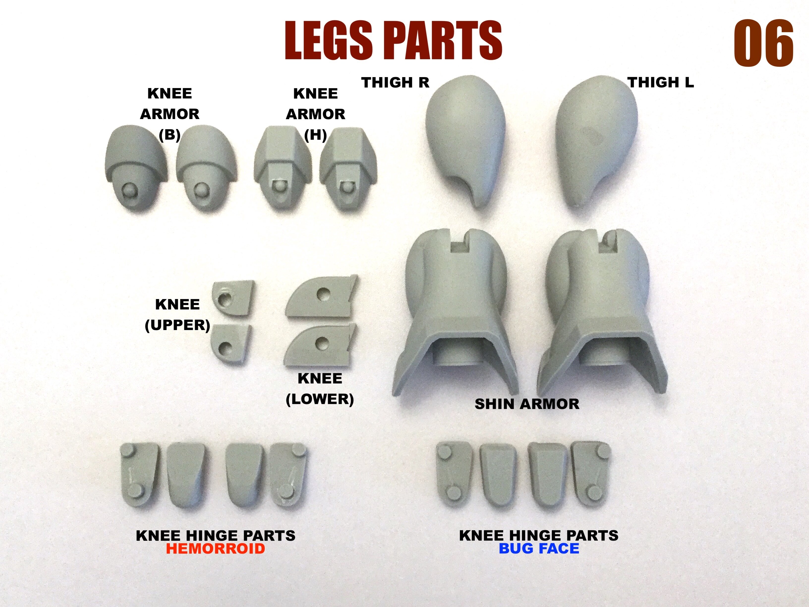
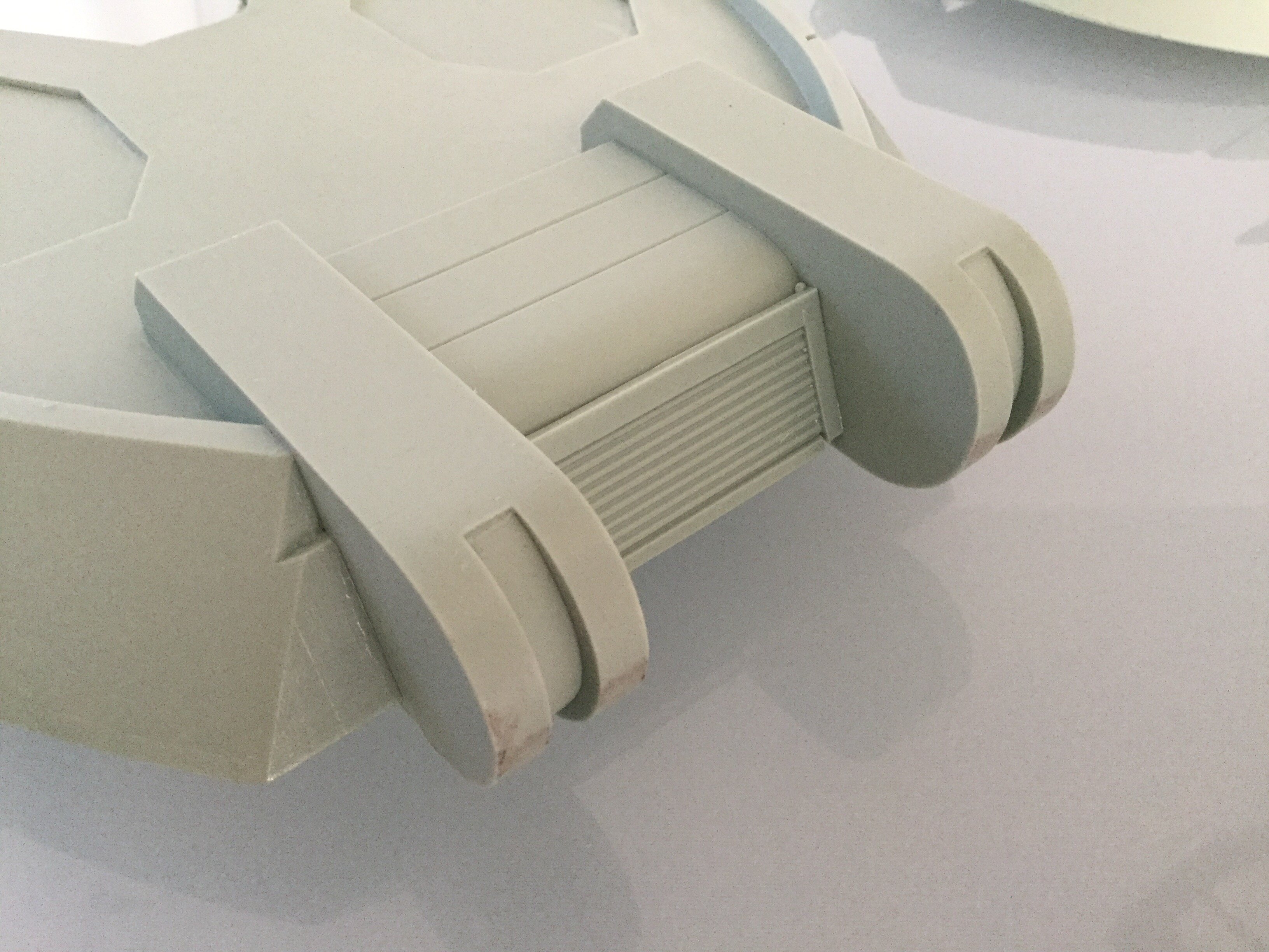
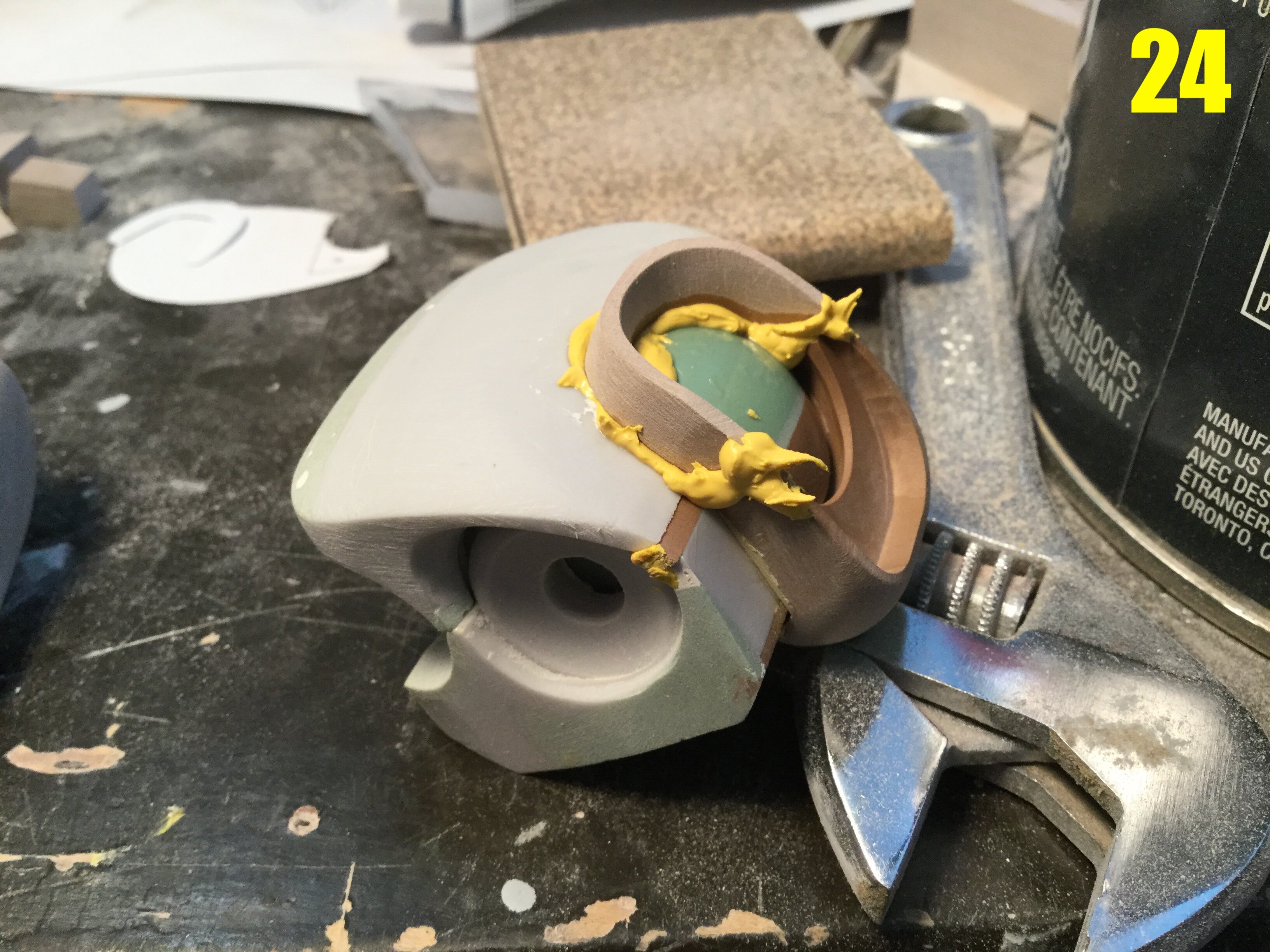
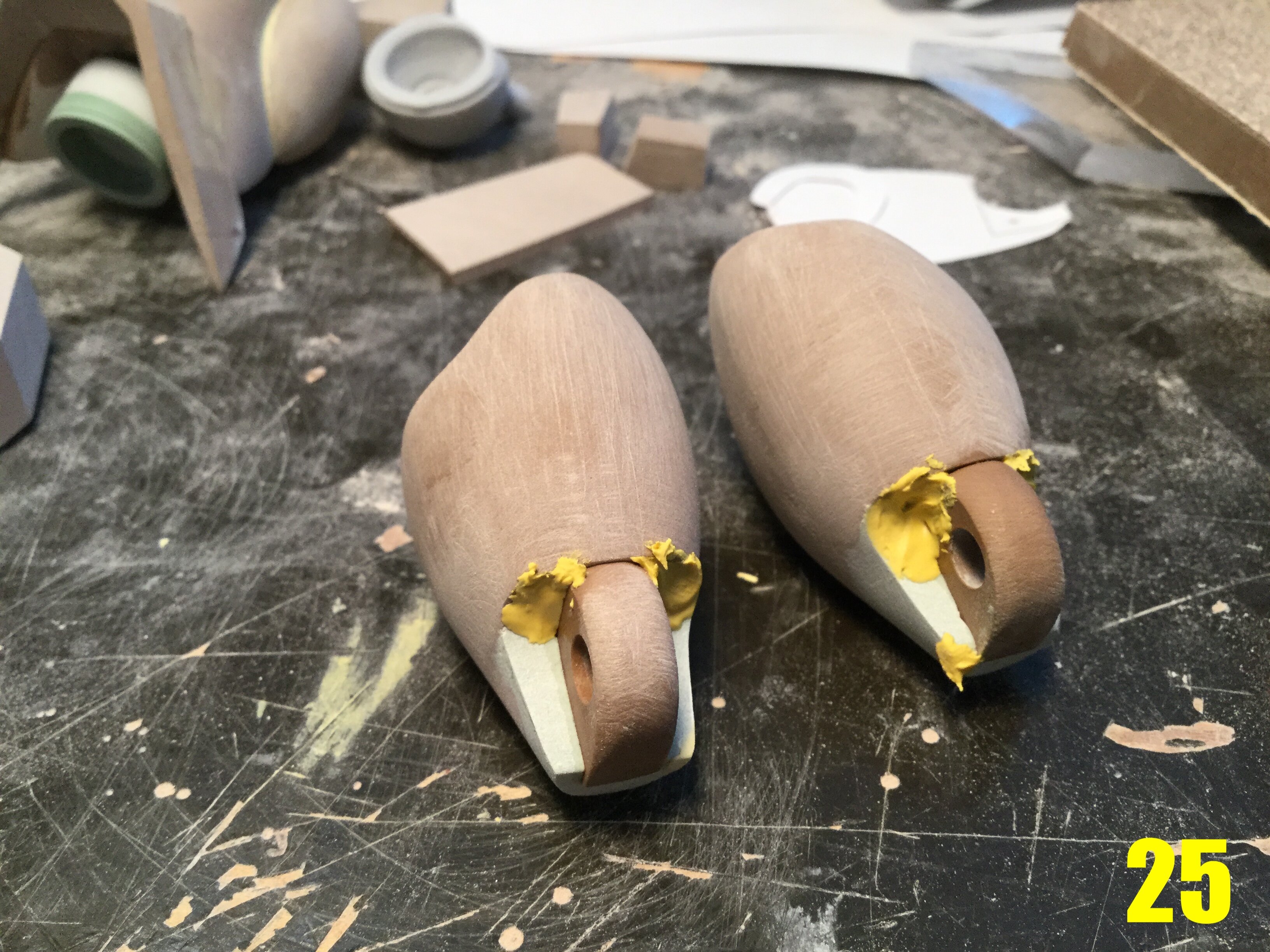
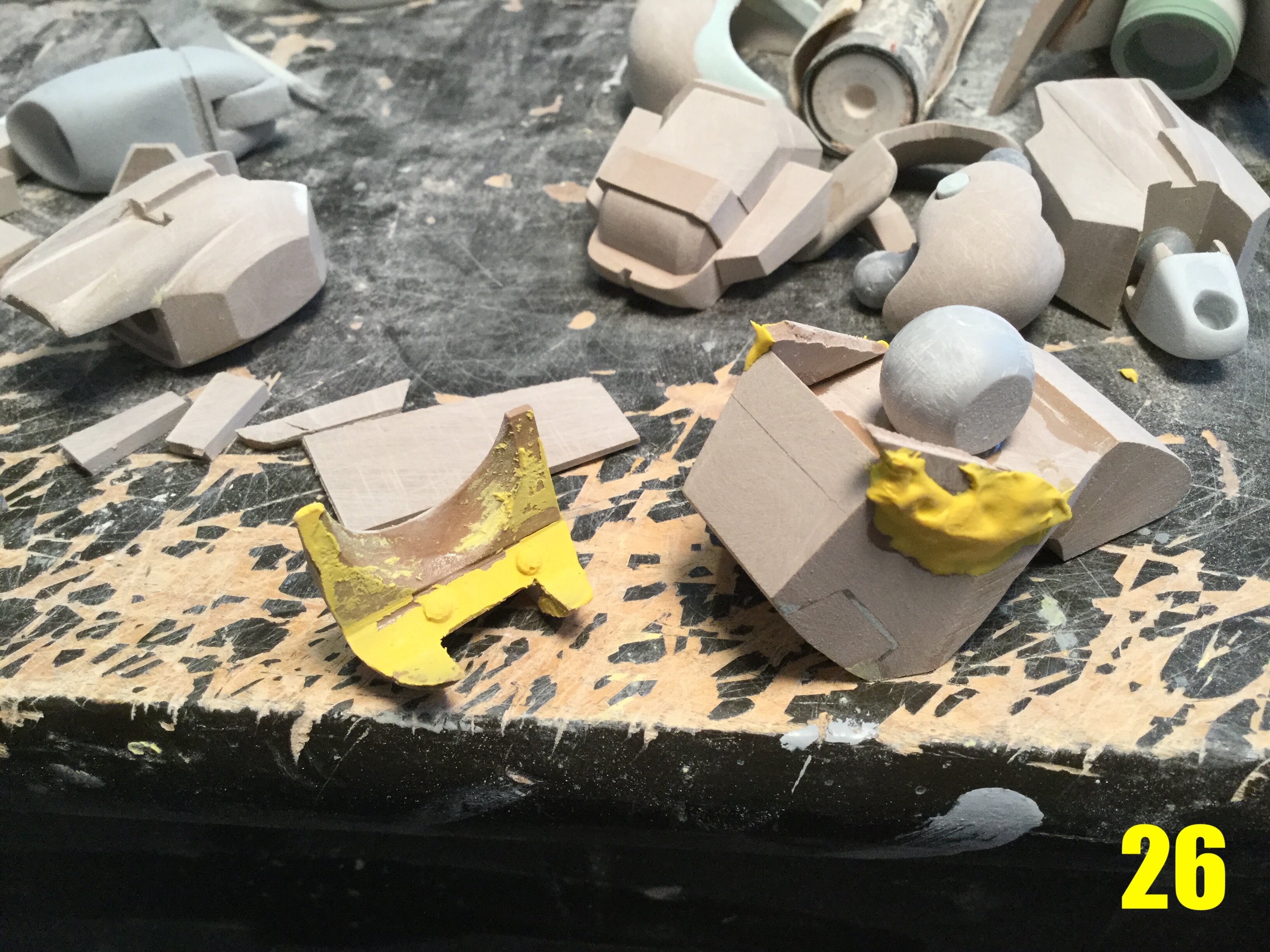
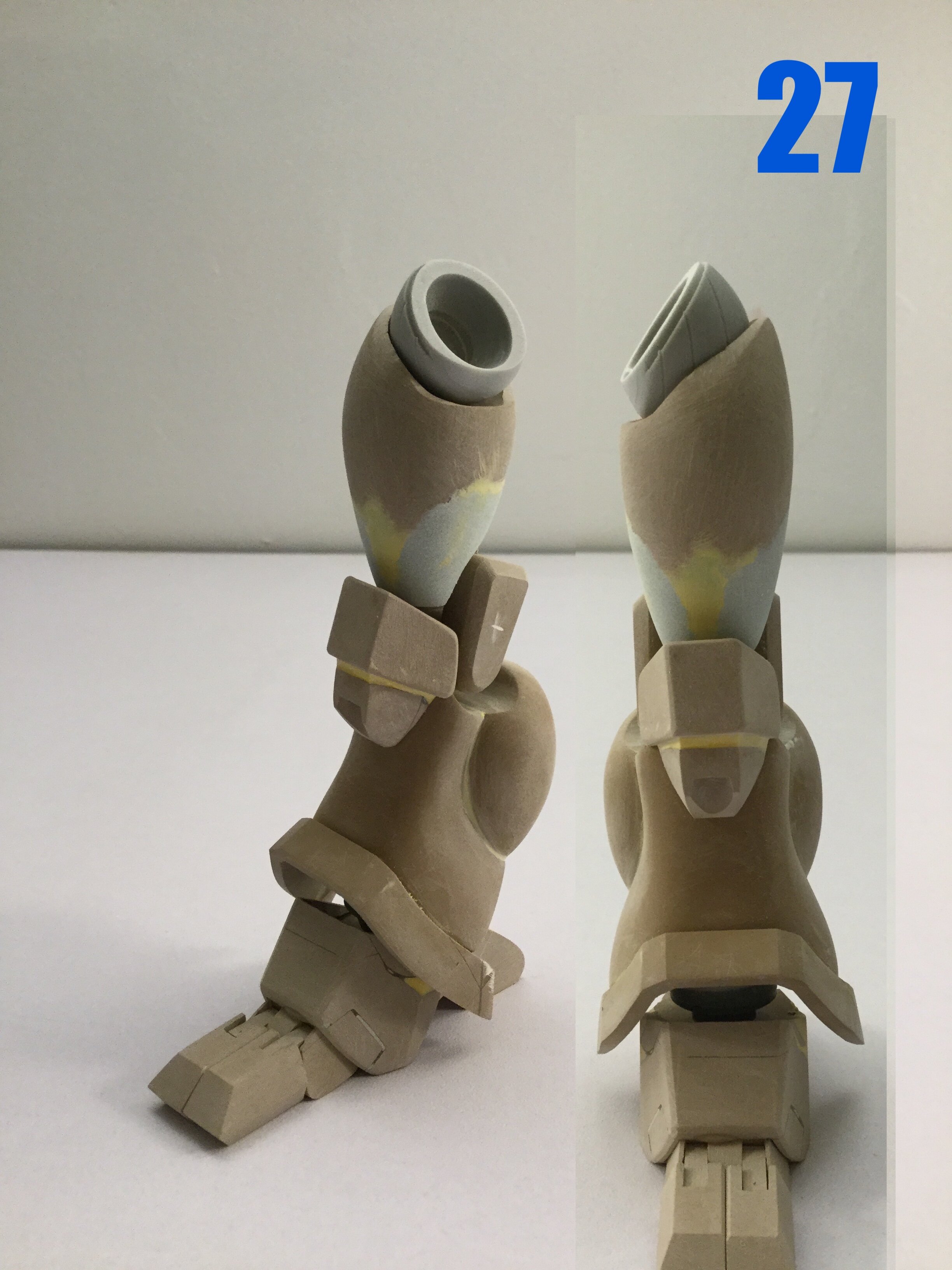
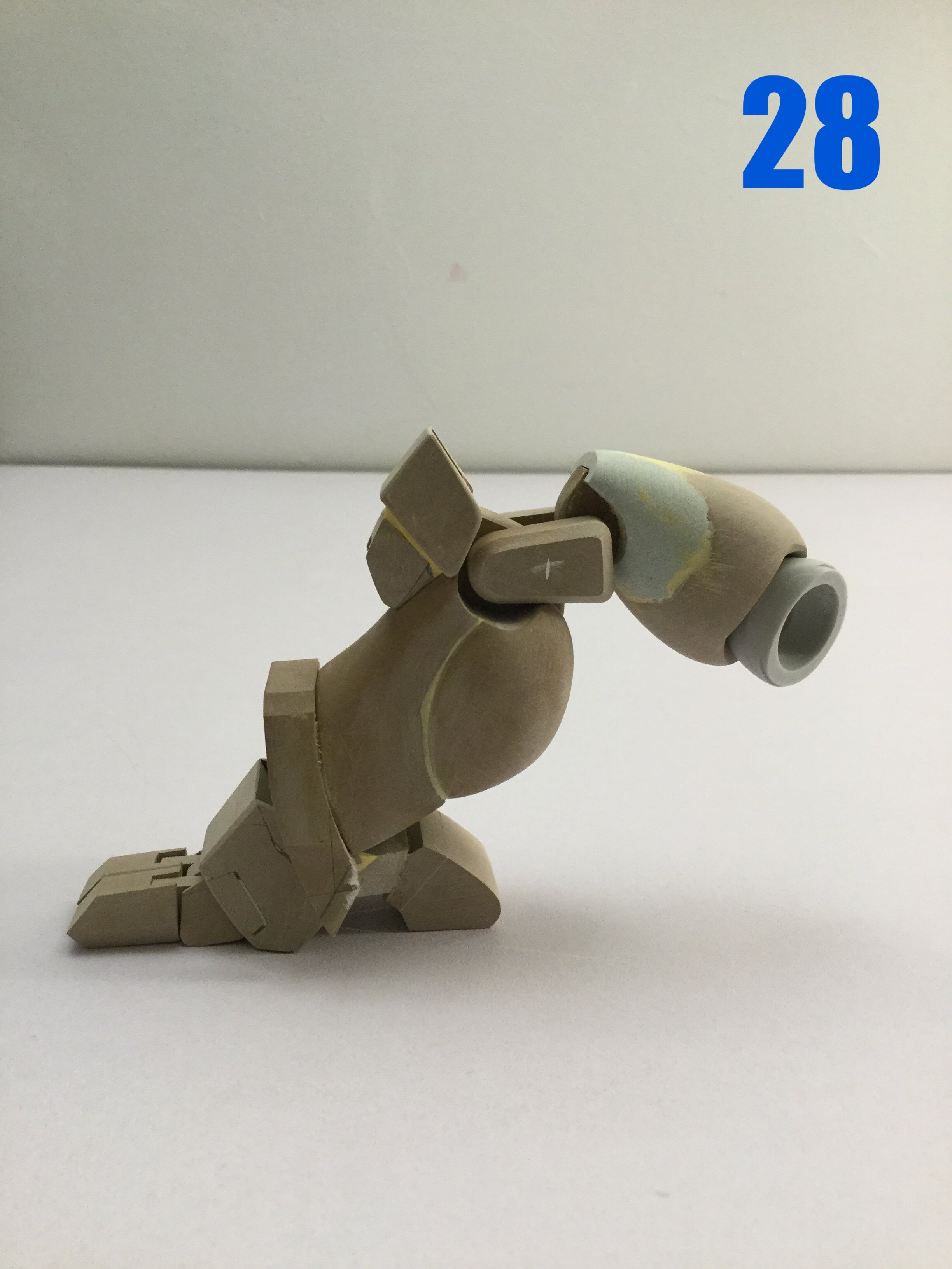
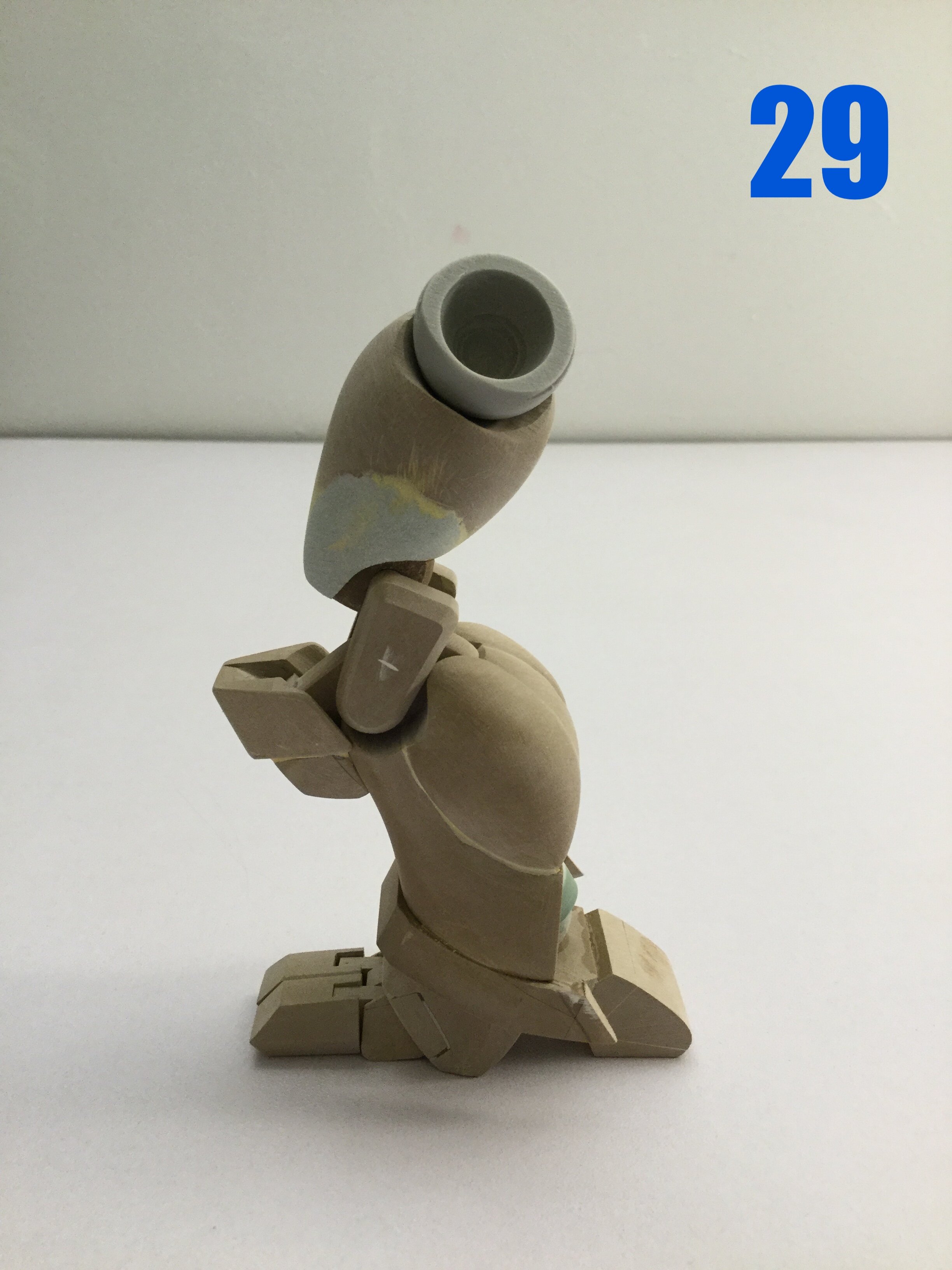
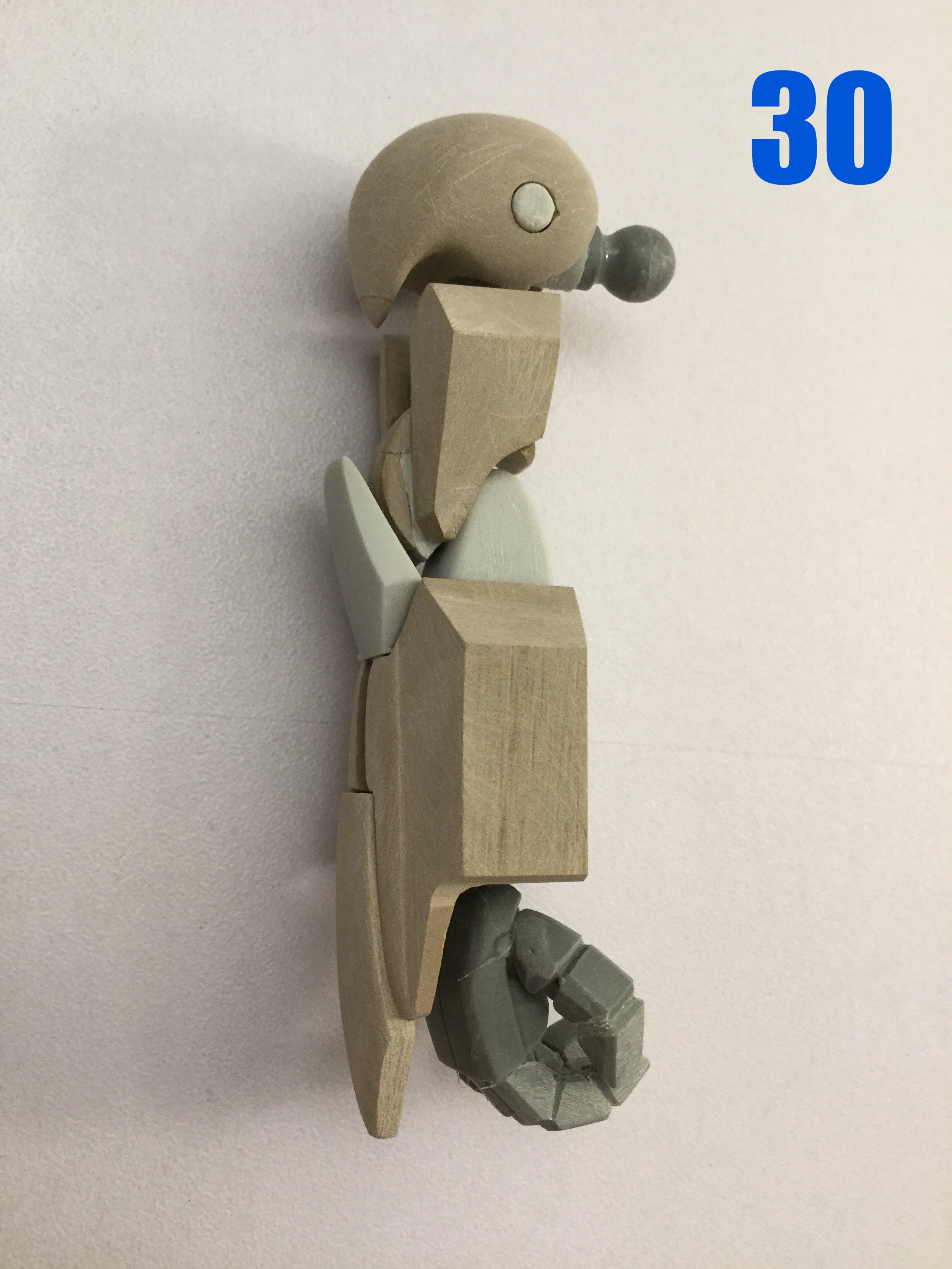
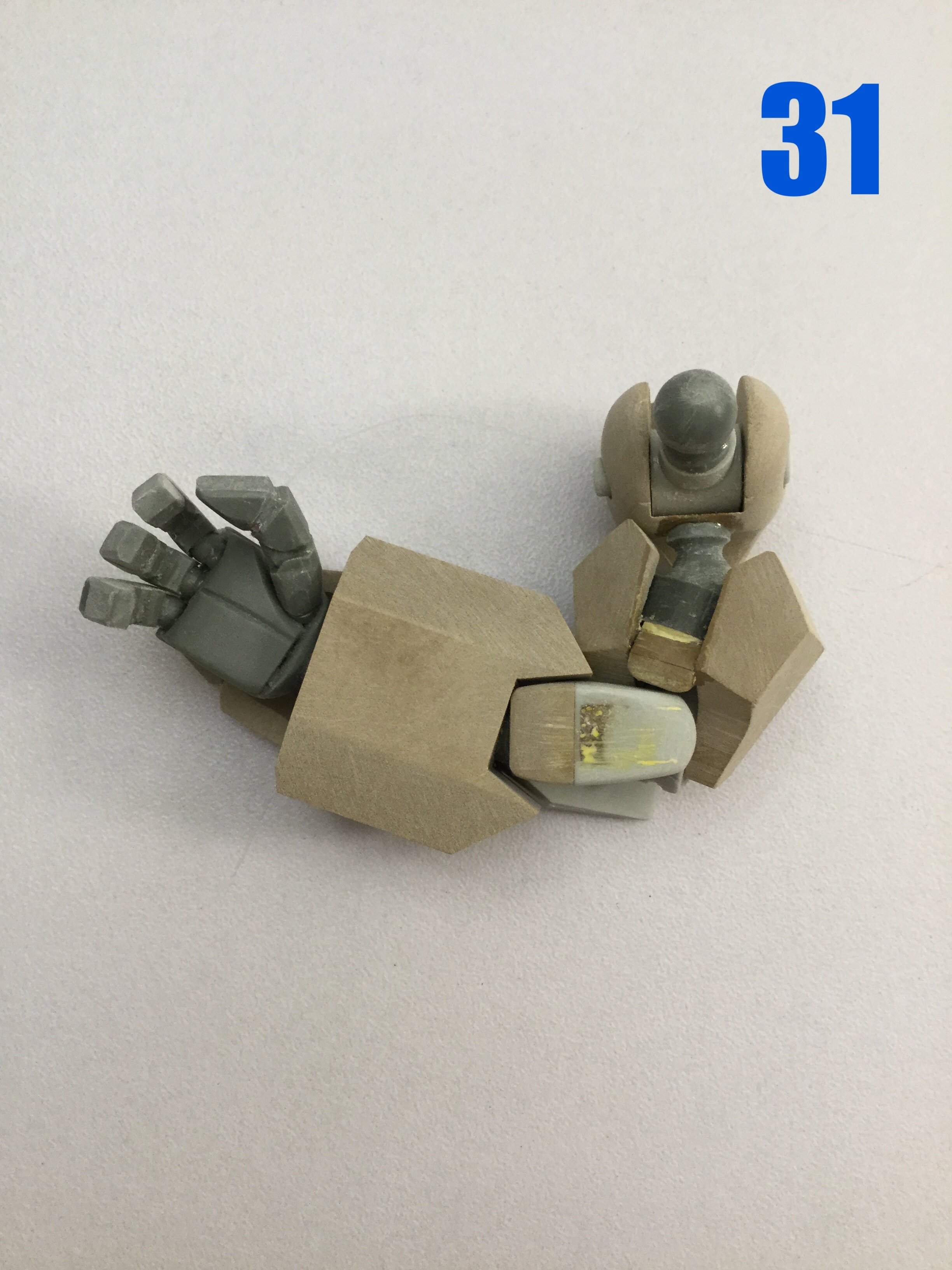
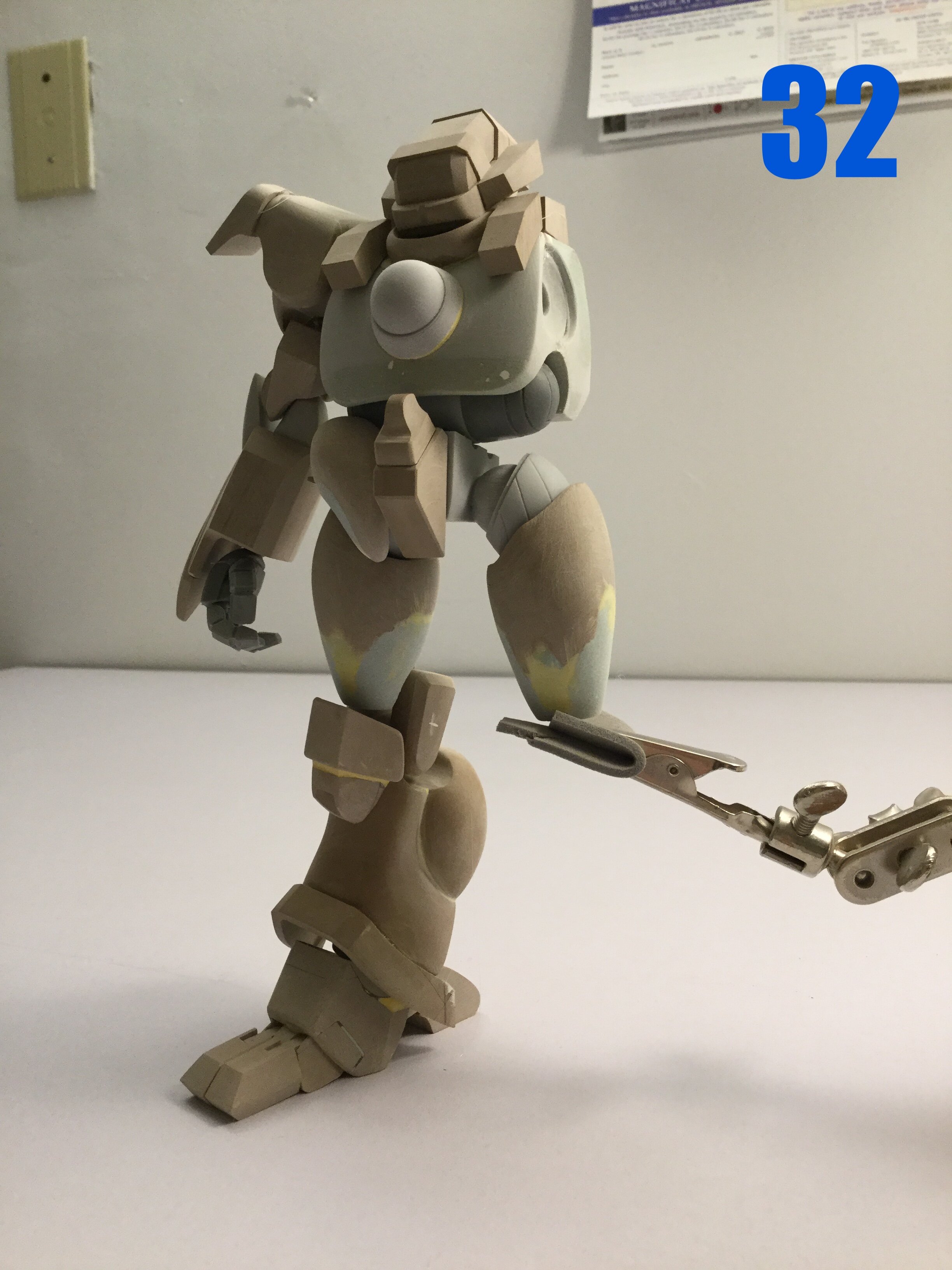
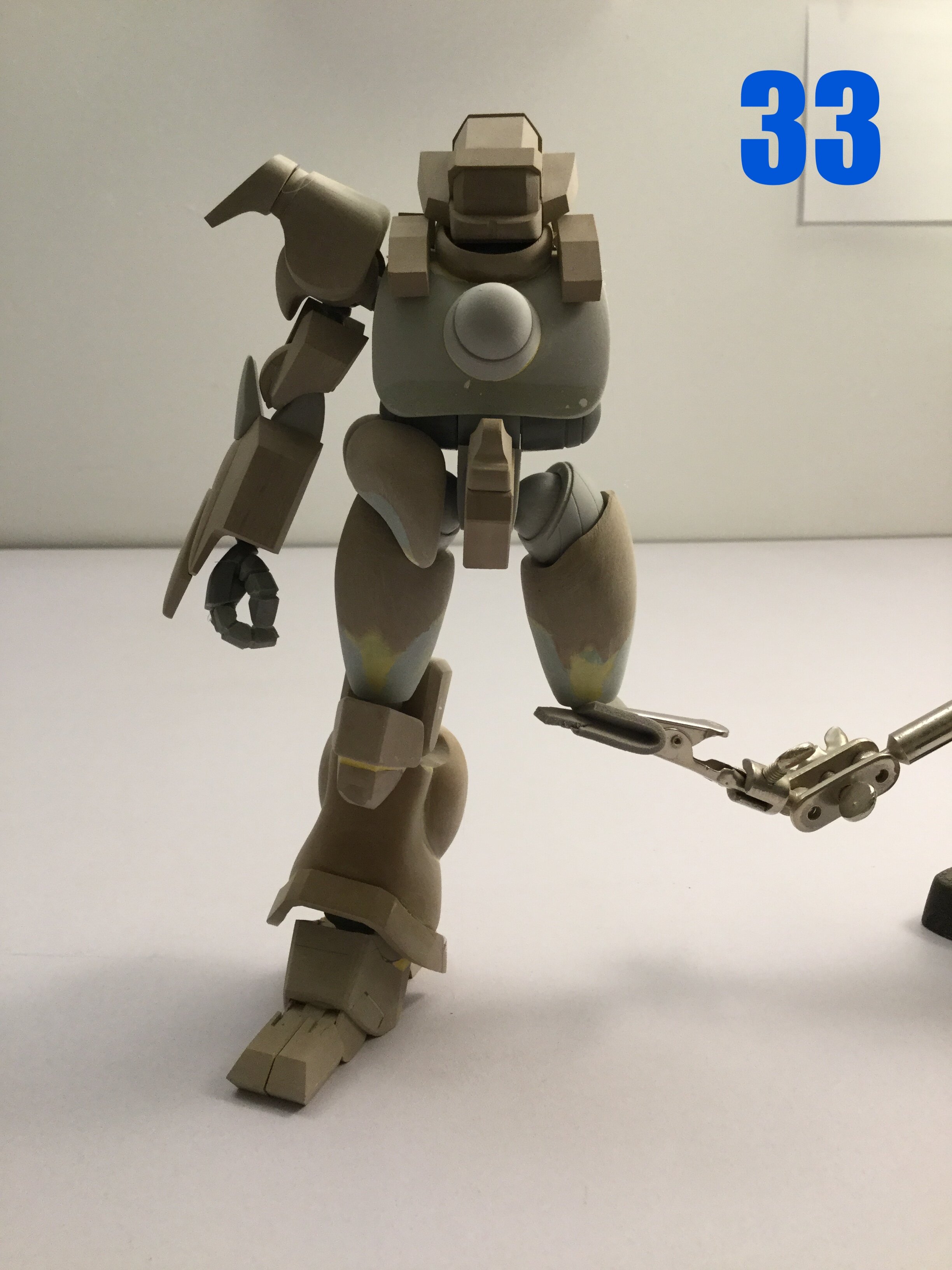
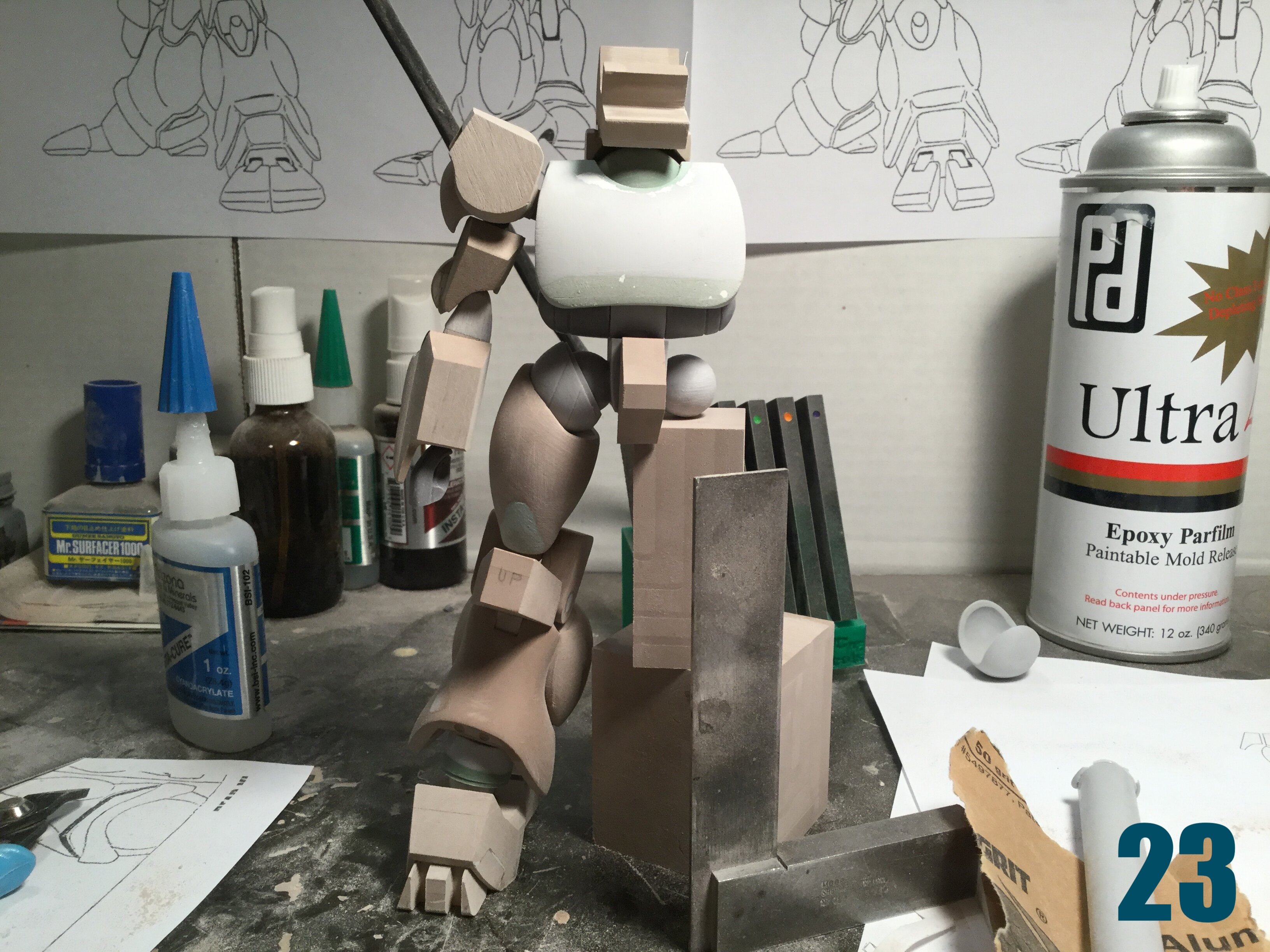
Captain’s log: Friday, January 28th, 2022. So this week has essentially been a polyester putty extravaganza: lots of parts need to be puttied and formed against other shapes to create a secure fit. I really like Tamiya’s polyester putty, but I do wish it would harden a bit faster. Pic 24: the collar for the Hemorroid variant is shown here. Bug face will require a whole different collar, head, and neck pivot mechanism, but that’ll be for another time. Pic 25: this is an earlier pic of the thighs. I have since widened them to make them fuller in the knee region. This is a result of following diagrams, then determining that the 3/4 view looks better with more volume, so I build them up with more putty. It’s not a very scientific approach, but it works. Pic 26 shows the main foot module in-progress. The range of motion was good enough to allow me to hide some of the gaps in the ankle without creating any binding. It’s one of those things I figured out after all the ankle armor was sculpted and in place. Pics 27-29 show the range of motion in the leg, which is as good (if not slightly better) as on the MK I. The knee design offered a really simple but effective double-joint system possibility that’s even more reliable than on its predecessor. The lower calf armor is still missing, but if it causes any binding, then it too will be hinged. The toes are actually separate and you’ll be able to pose them splayed with a little tweaking. Pics 30 and 31 show the arm, which like the leg, demonstrates an impressive range of motion considering its clunky design. It’s really not that hard if you’re willing to make three joints do the work of one! Pics 32 and 33 show most of what I’ve got so far. You’ll have to excuse the poor fit of the skirt: it’s actually the left and right skirt still bound together as one piece and I didn’t want to risk breaking it. Fully assembled, BIO LLOYD II will stand almost 18.8cm tall, which I think is just a hair taller than the MK 1…Can someone check that for me? Anyway, that’s it for this week. MOAR exciting updates coming soon, so stay tuned!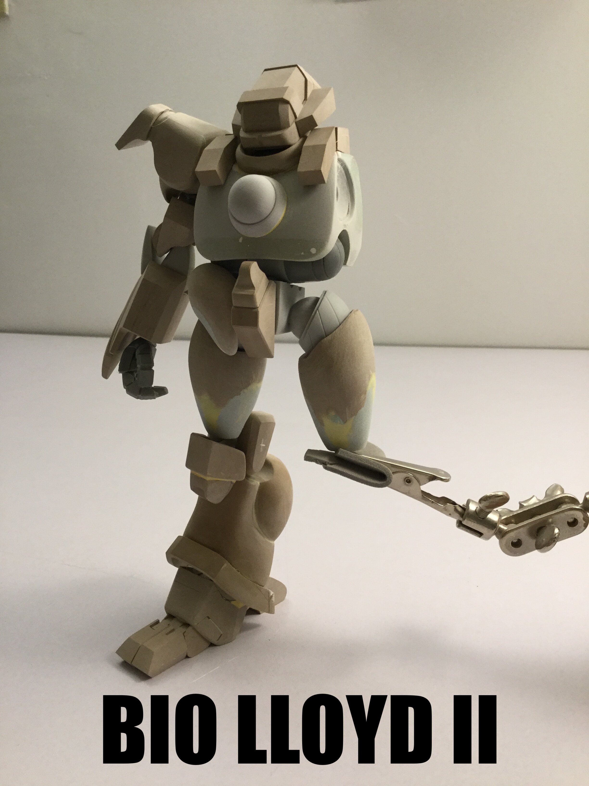
- 150 replies
-
- 3
-
-
- southern cross
- robotech
- (and 4 more)
-
1/48 SOUTHERN CROSS BIOROID PART II
captain america replied to captain america's topic in Anime or Science Fiction
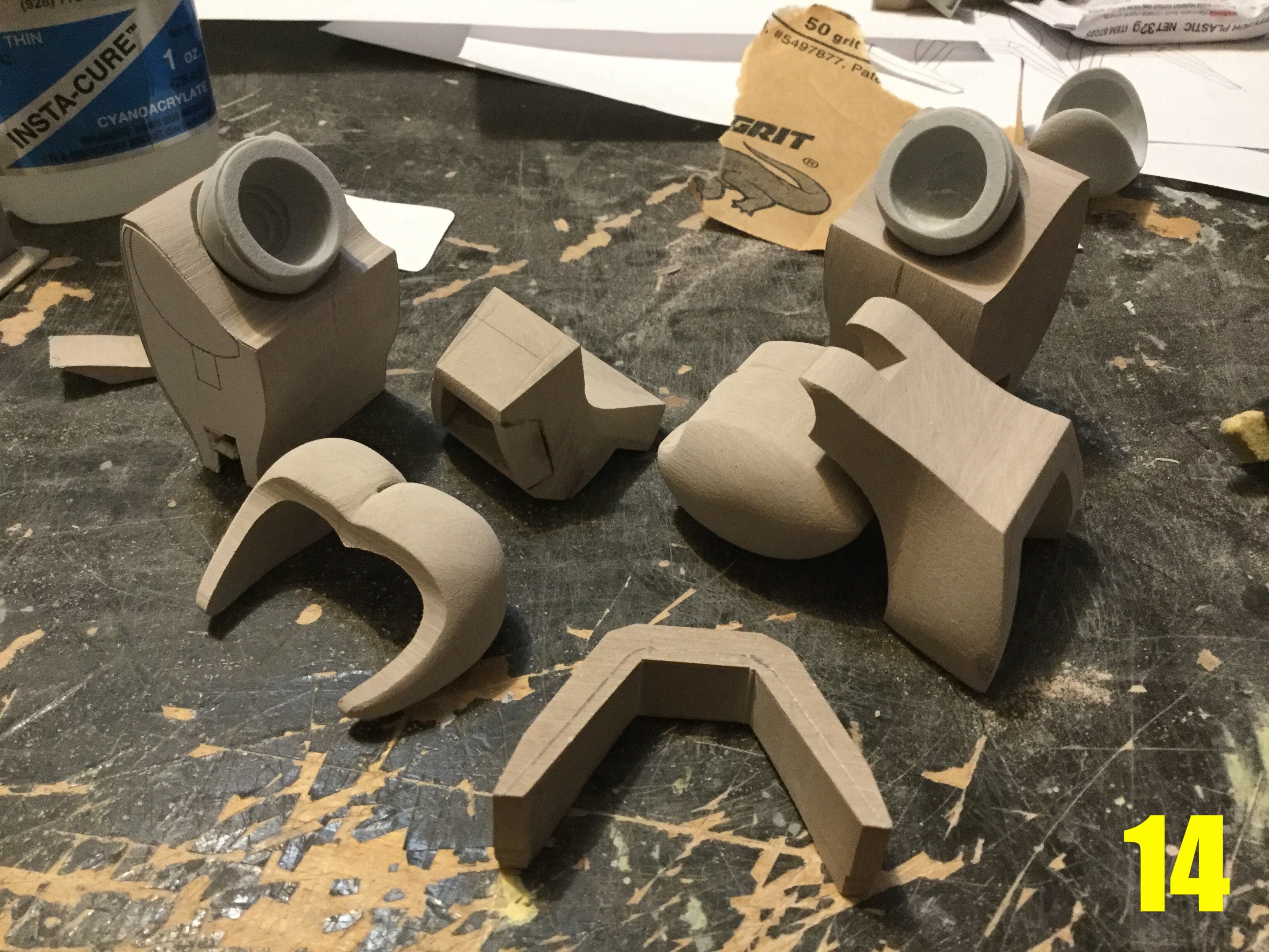
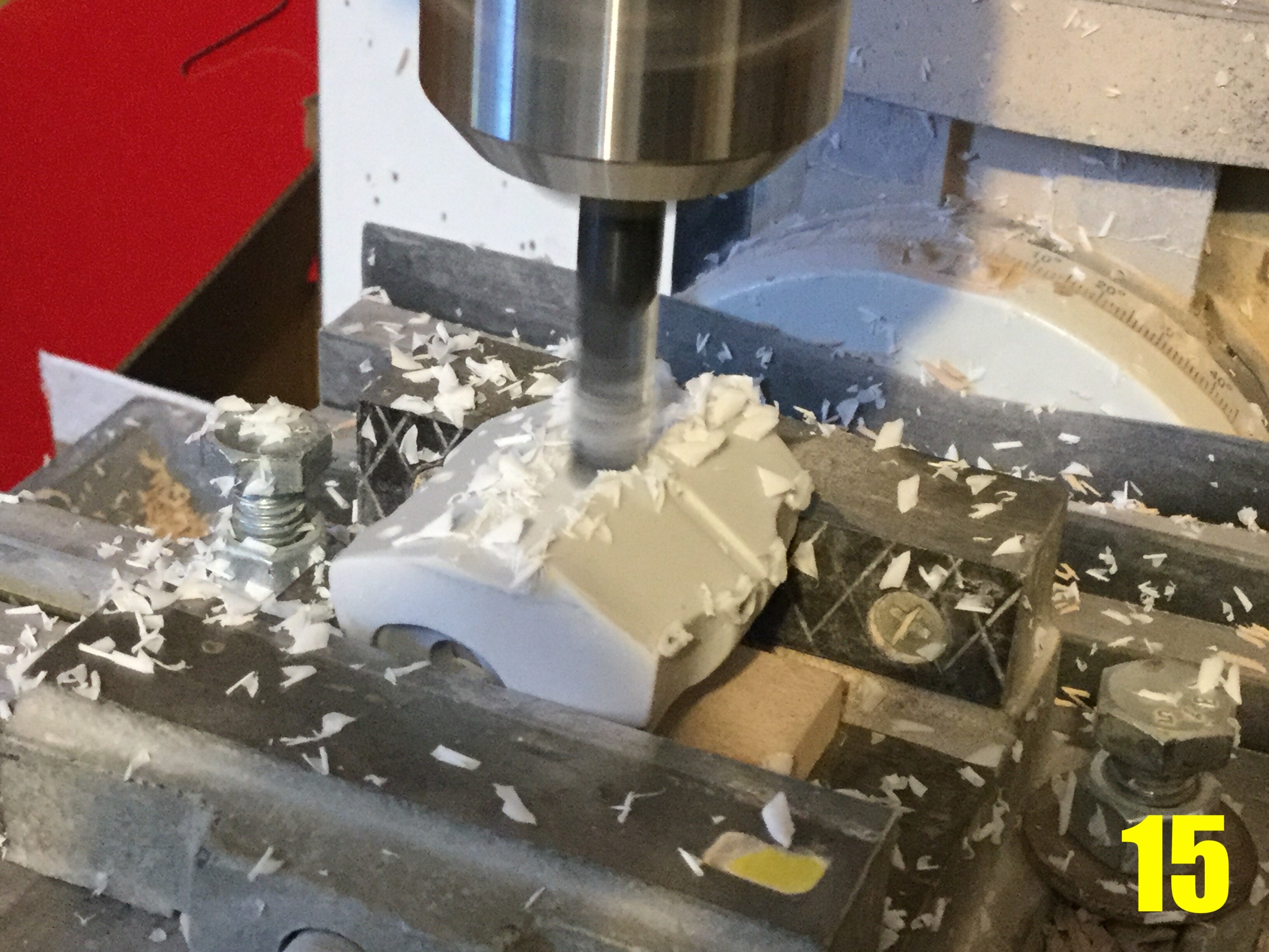
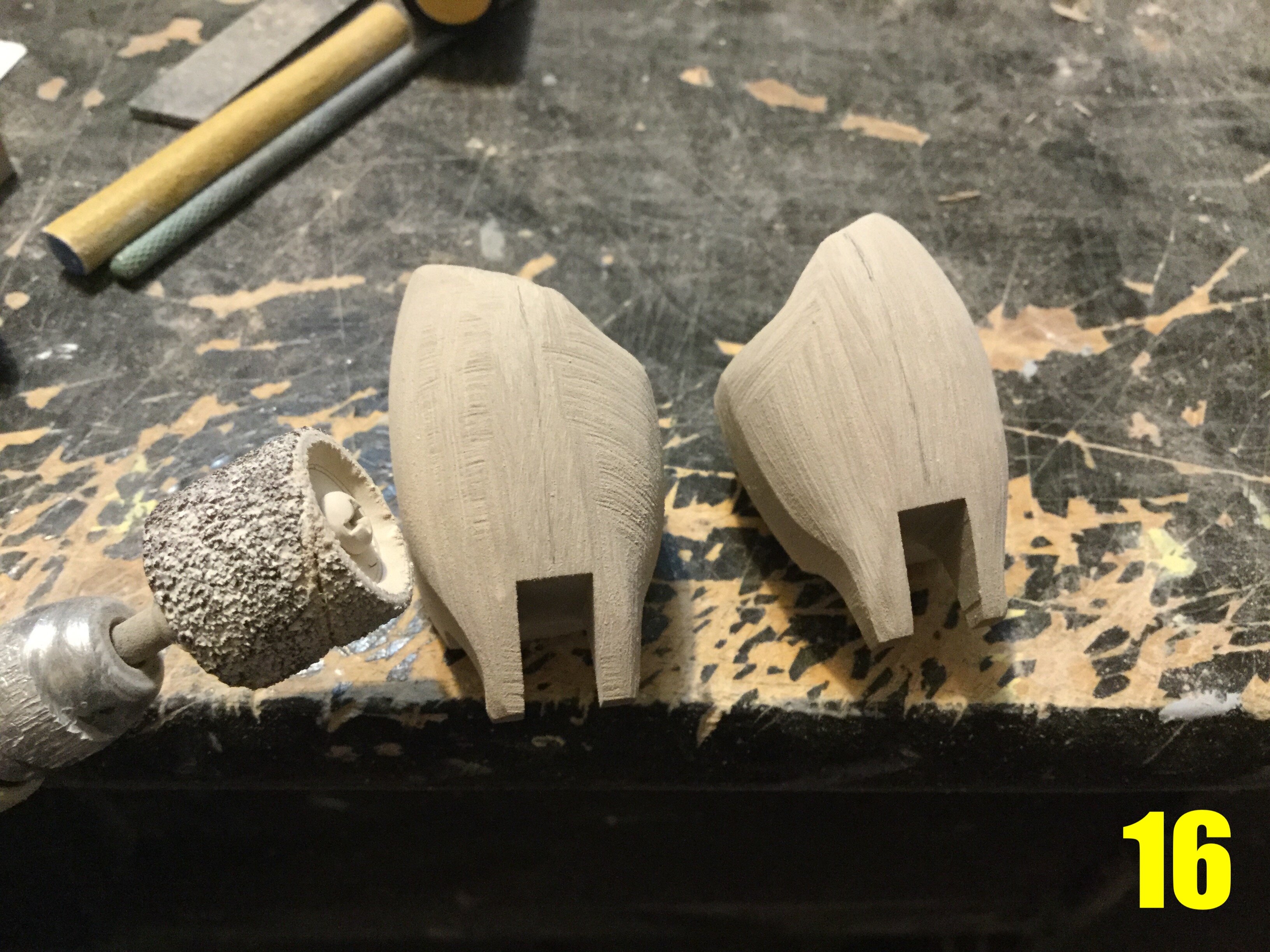
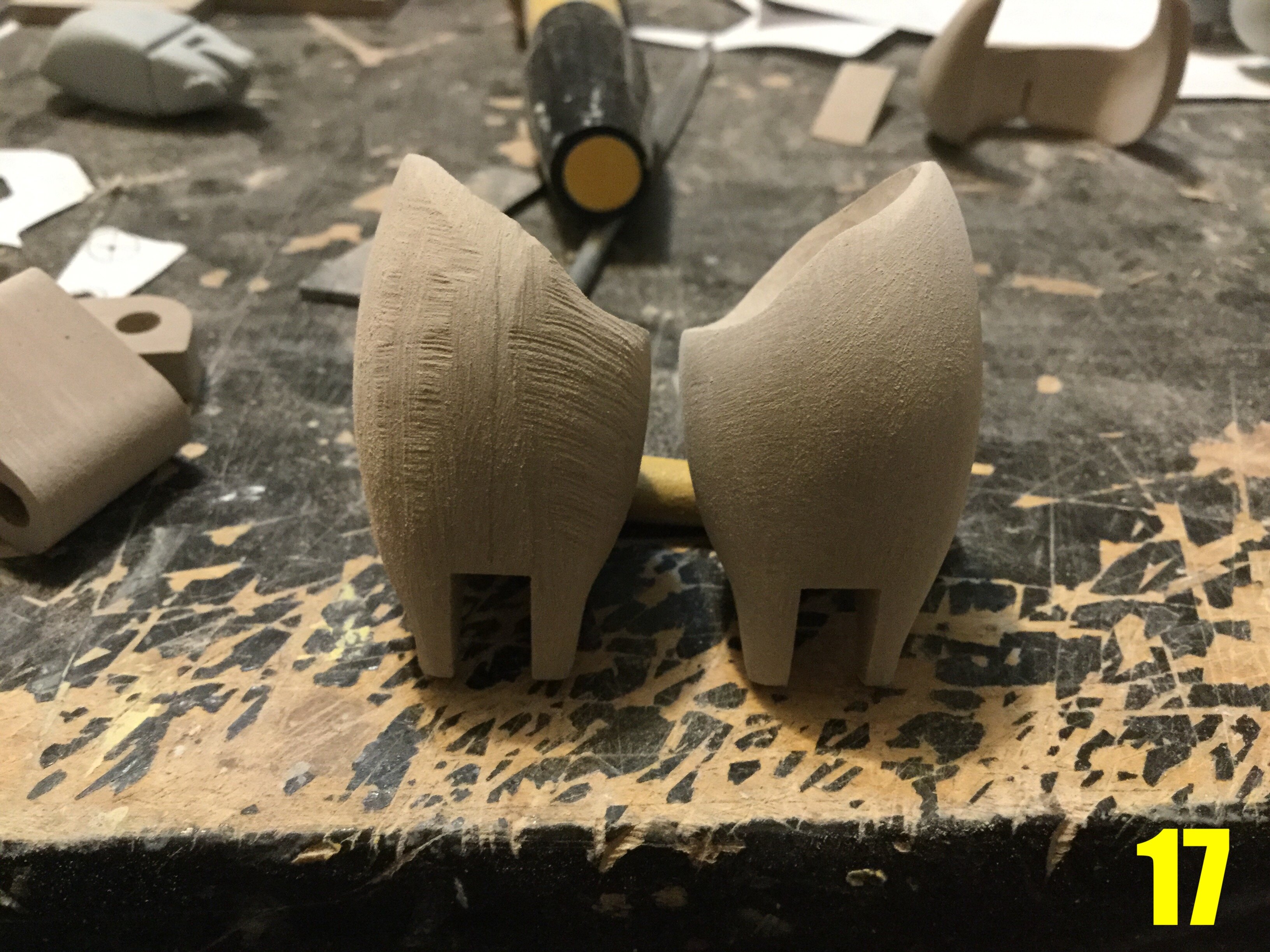
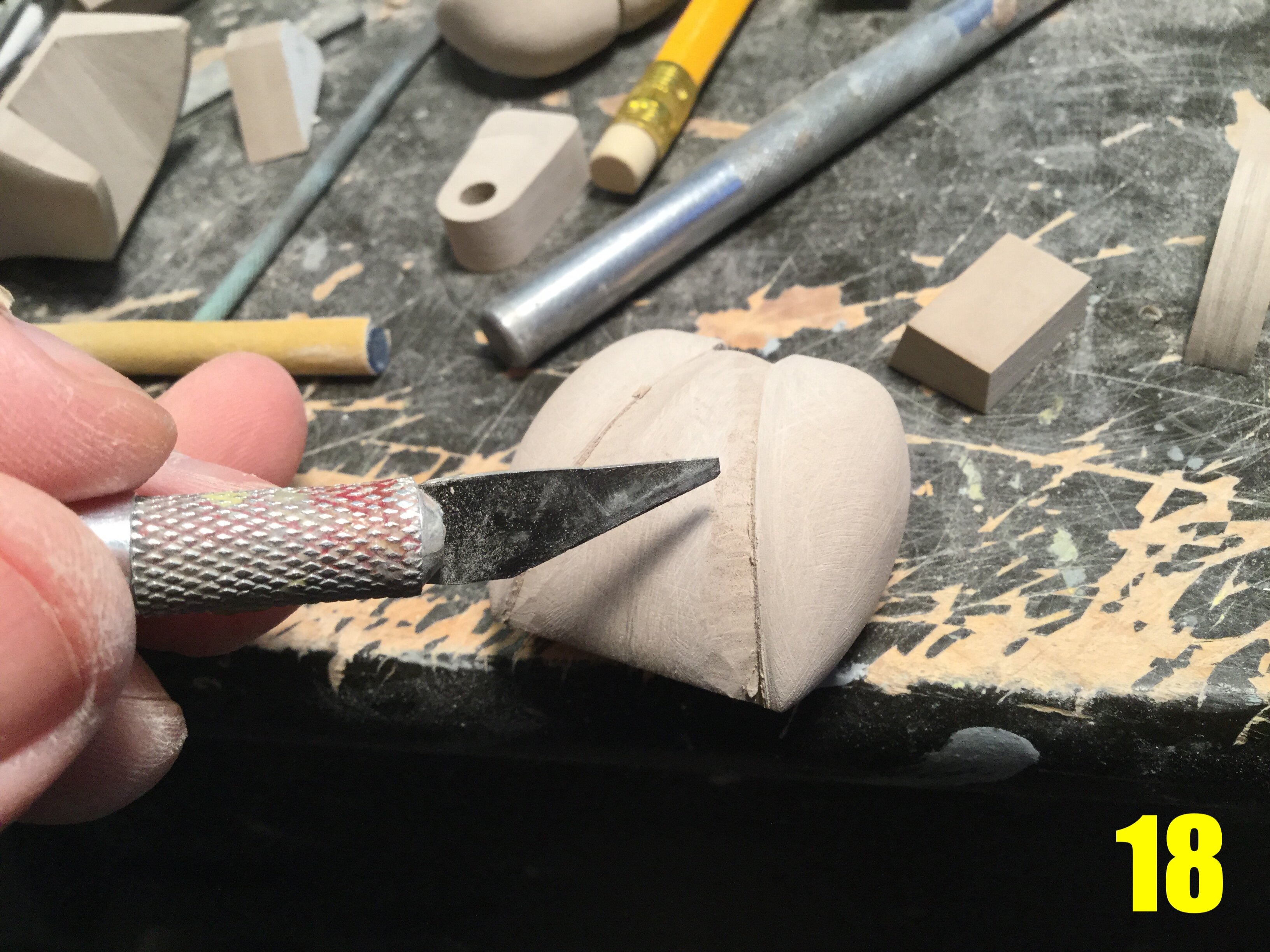
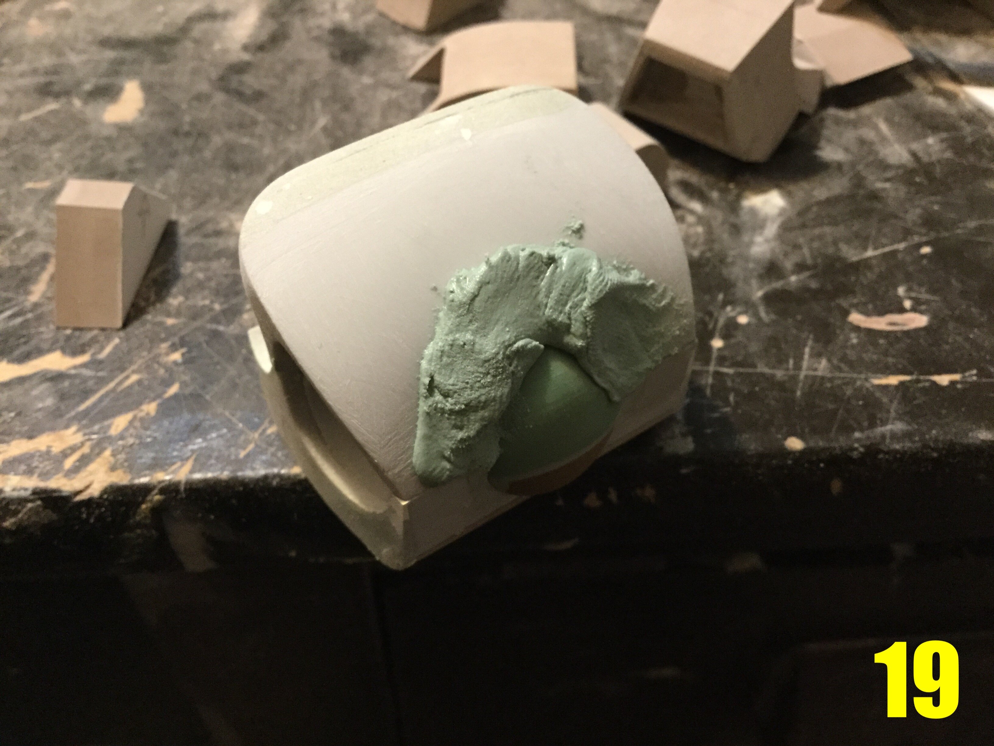
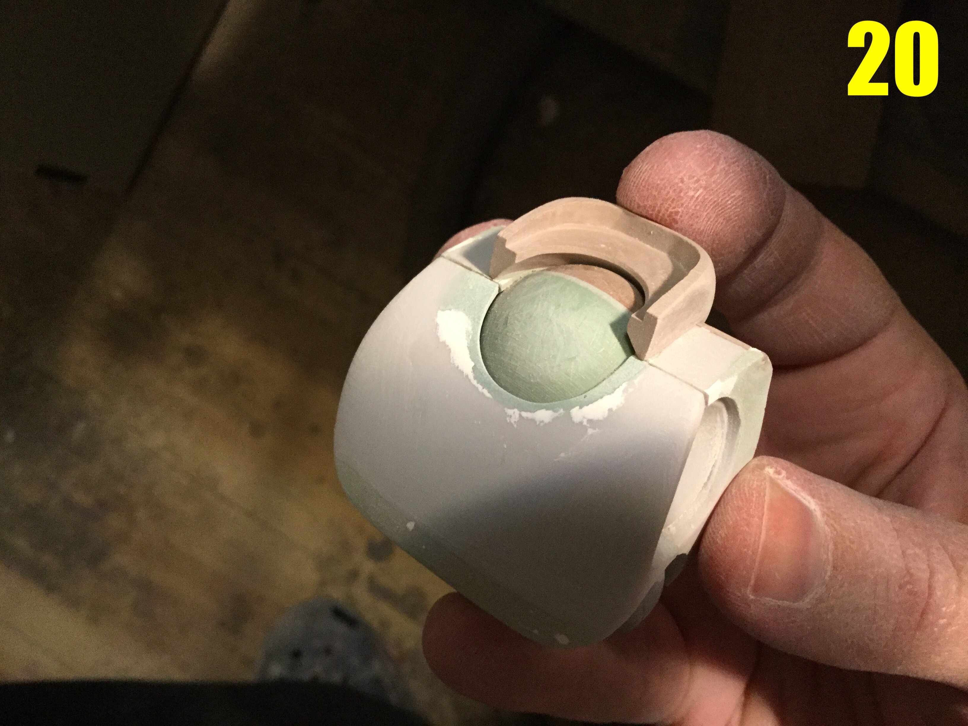
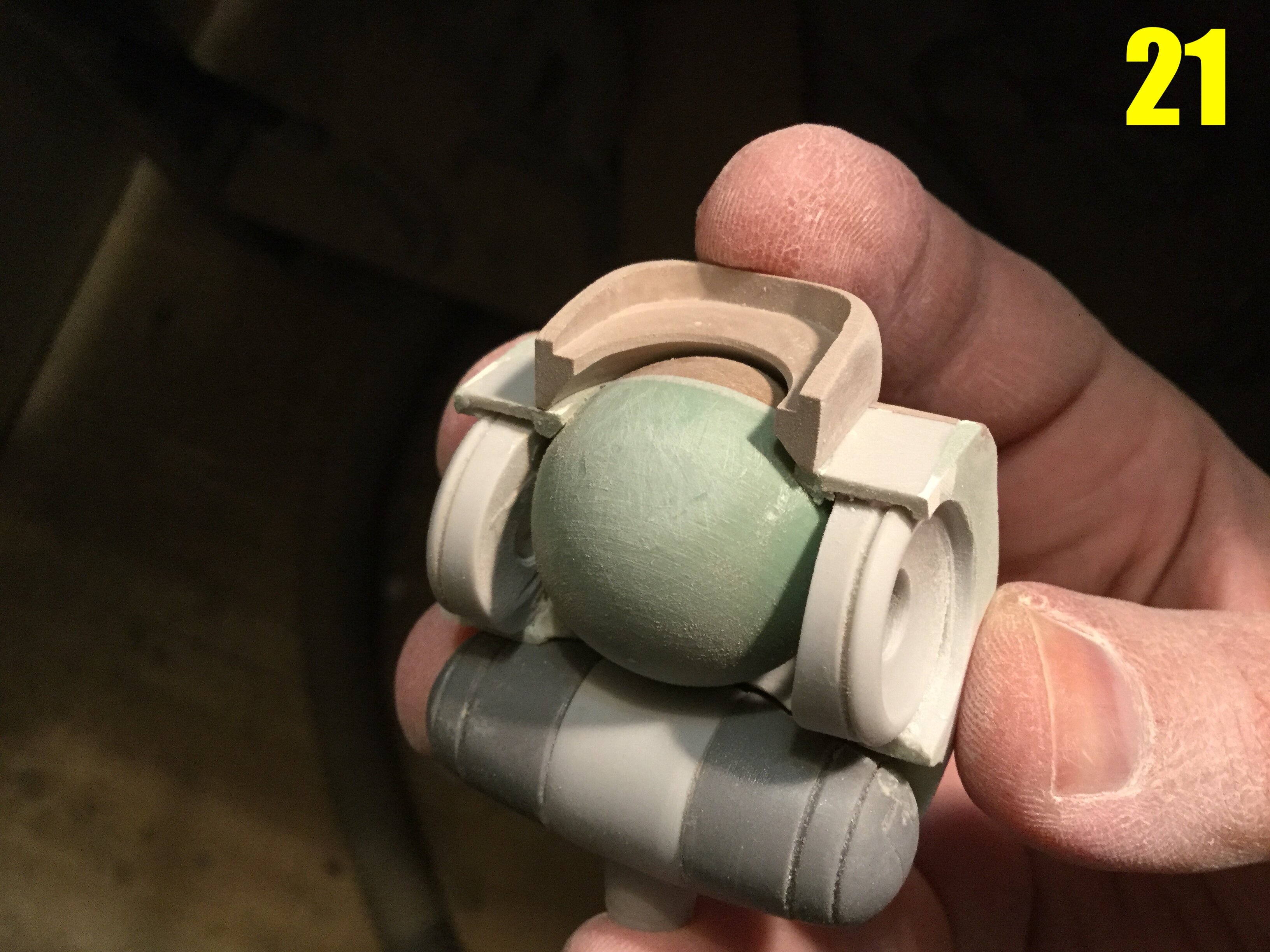
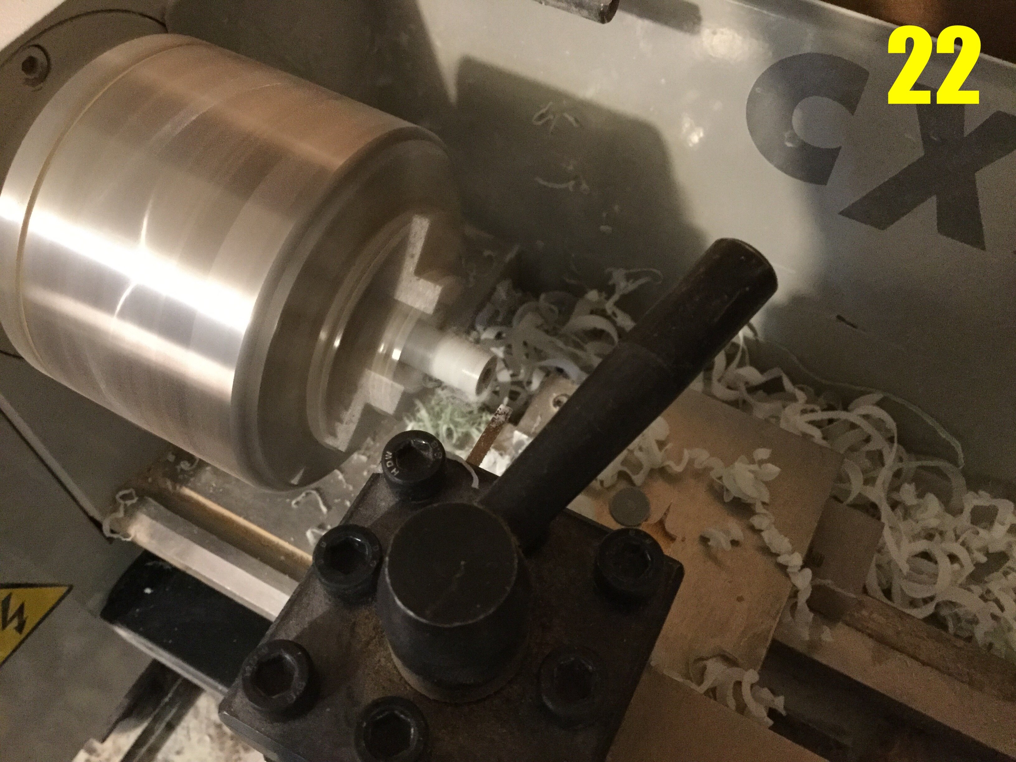
Captain’s log: January 20th. Pic 13: Once the parts have been shaped as far as they can be on the mill, it’s time to break-out the rotary tool and begin grinding the compound curves into the blocks. This part is more art than science, requiring a good eye and making sure to remove just a little bit of material at a time. Pic 14: here you can see a variety of parts in various degrees of refinement. Since the hip sockets on BIO LLOYD MK I worked so well, I decided to import these into the MK II as well. In total, five parts will carry-over from the previous iteration: the hip socket cups, and the three midsection pieces. A couple of other parts will be scavenged from the MK I, but they will be heavily modified. Pic 15: one of those heavily modified parts is the main torso back, which you see here undergoing major surgery. The only reason I retained this part (and the breastplate) is that it houses the excellent inner shoulder socket assembly, and would have been much longer to start again from scratch. The height, depth, upper width, as well as the abdominal joint mounts are all different, and require considerable modification. Pic 16: the blocky thighs from pic 14 are back, having been ground-down much closer to their final shape. An interesting detail about this MK II is that it’s more high-waisted than its predecessor, so shorter torso and longer thighs. Pic 17: the same parts with the left thigh now having received some rough love from the sanding sponge. This is a tedious process, requiring the removal of vary little material at any one tome, and also checking to make sure that the shapes and symmetry are maintained. Pic 18: the line-art shows what appears to be a « calf-like » crease pattern on the back of the lower leg armor, so I start by sketching out the plot lines with a pencil, then running over it carefully with a hobby plade, followed by some chiseling. A variety of files and sandpapers will be used to iron-out the shapes until everything is nice and smooth. Pic 19: just like the back, the breastplate has itself seen considerable re-shaping and modification. Here I’ve added some putty to close-up the neck hole around the cockpit. Pic 20 shows the same part and all the putty work that went into its alteration. The neck collar shown is for the Hemorroid variant: the Bug Face unit will have a completely different neck housing. Pic 21: the rough cockpit ball assembly in place. This too will require some modification, but it’s off to an excellent start. Pic 22: one area which I thought needed upgrading was the shoulder joint: because there’s a different shoulder armor on this variant, I decided to make something more robust and reliable fo the hinging mechanism. Pic 23: I’m quite pleased not only wth the amount of progress I was able to make in a single week but also with how attractive this mecha is becoming. While the design had numerous engineering hurdles to overcome, I can tell even at this early stage that it’s going to be more eye-catching than its predecessor, and has more hidden joints that will allow for, in some cases, even better range-of-motion than the MK I. I will cover all those little innovations in next week’s installment, so stay tuned!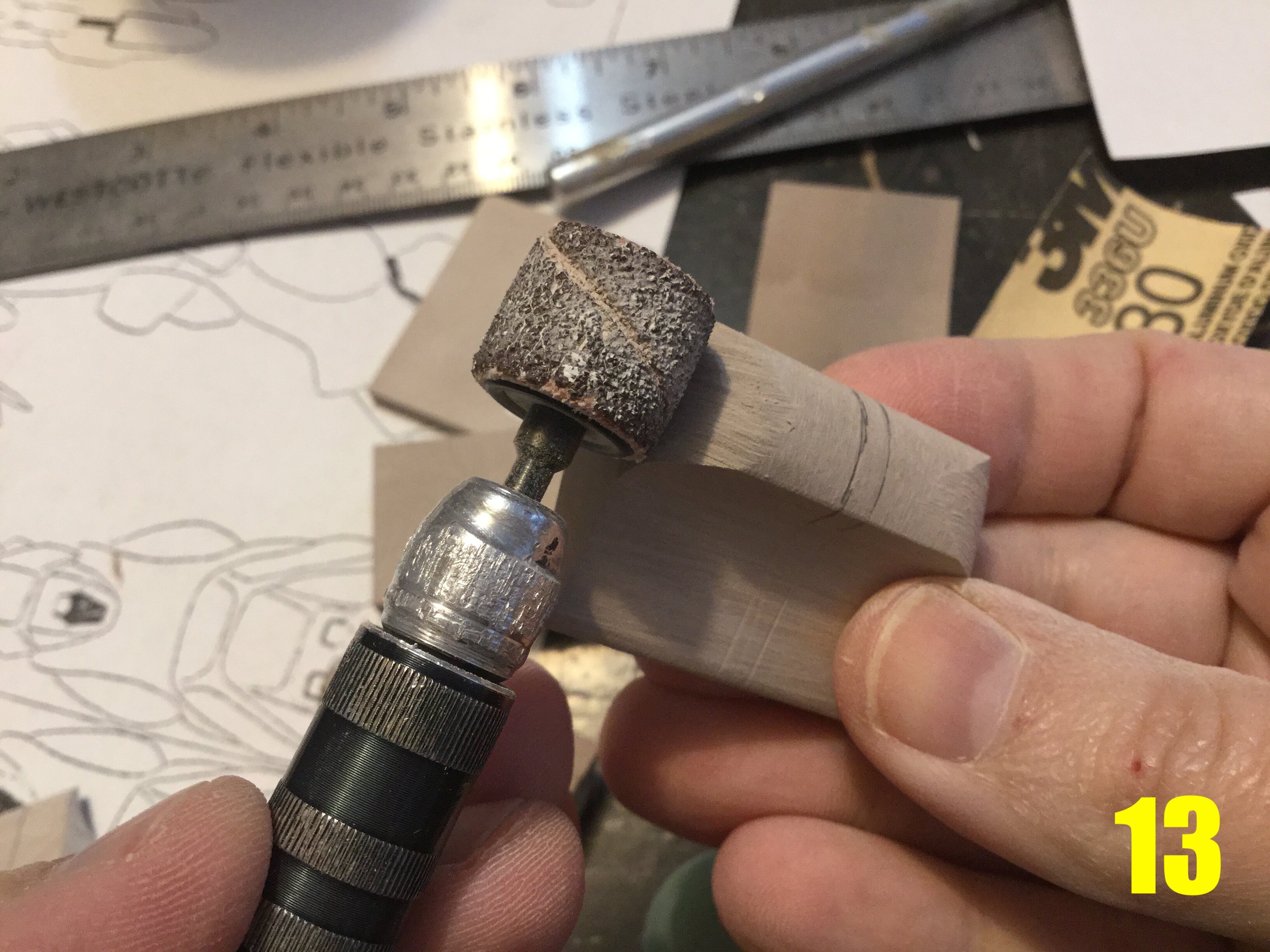
- 150 replies
-
- 1
-
-
- southern cross
- robotech
- (and 4 more)
-
1/48 SOUTHERN CROSS BIOROID PART II
captain america replied to captain america's topic in Anime or Science Fiction
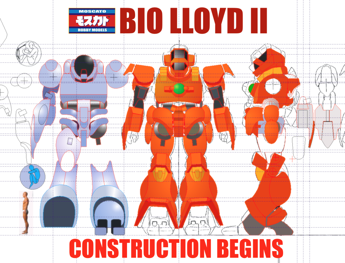
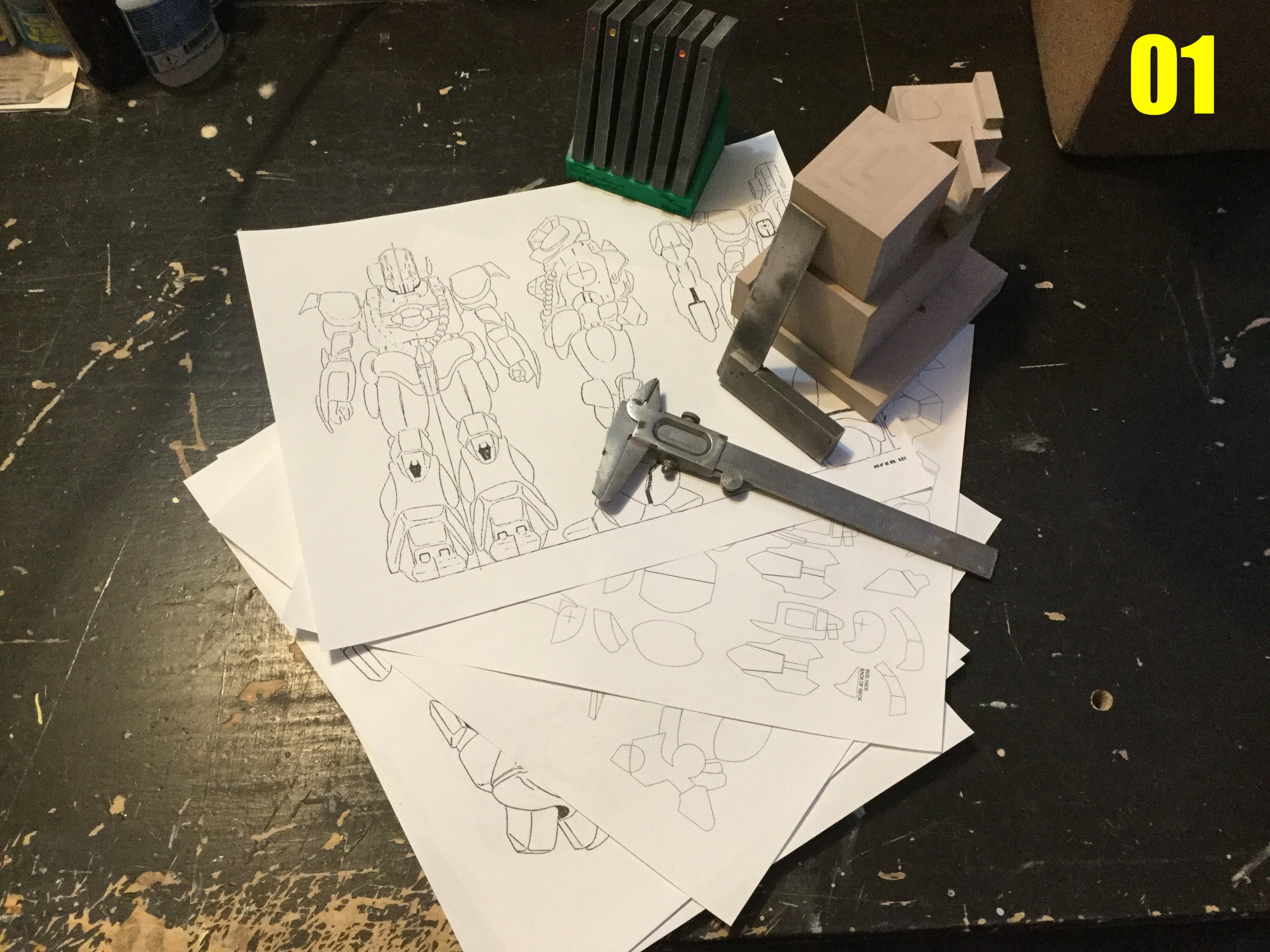
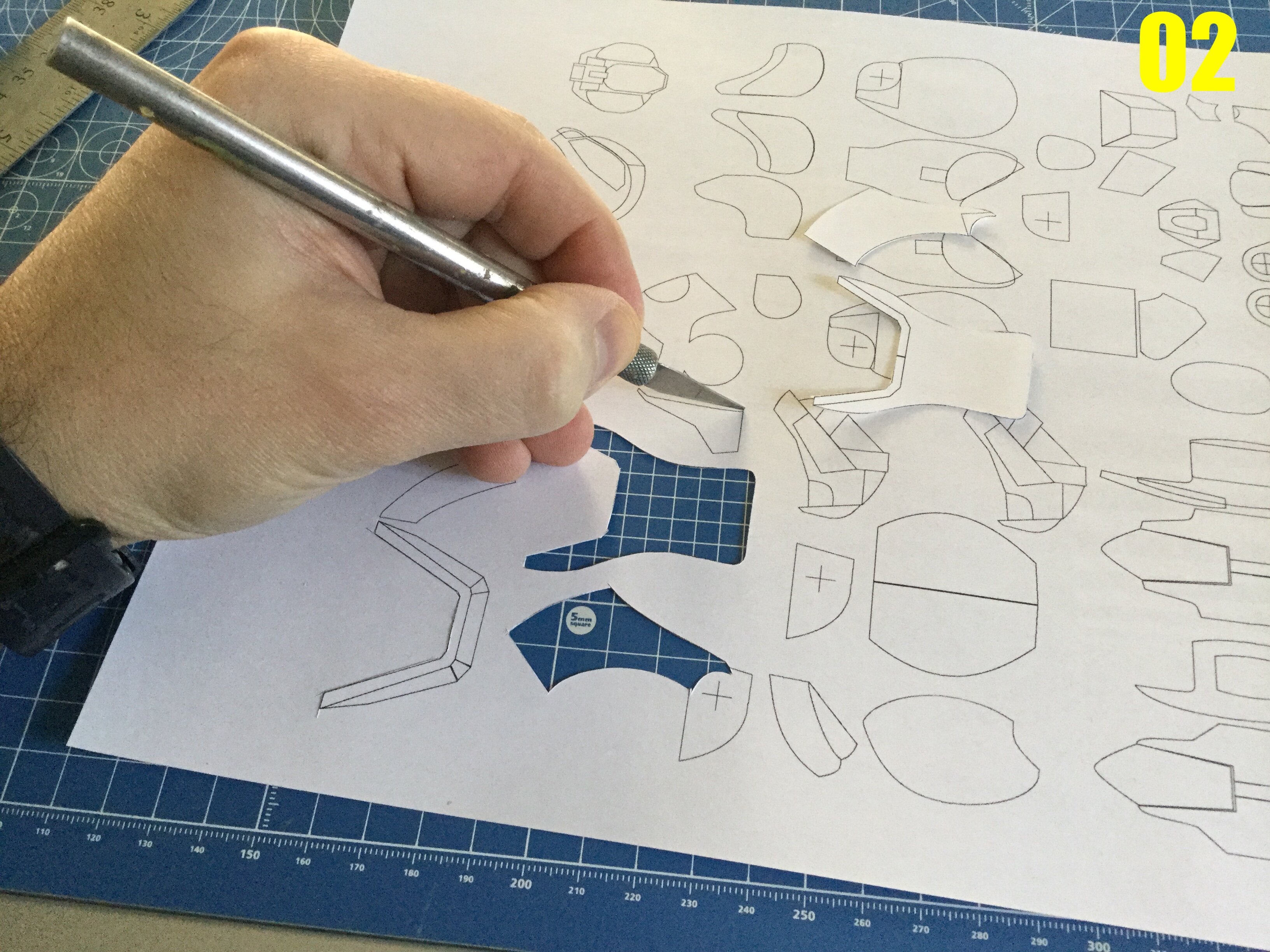
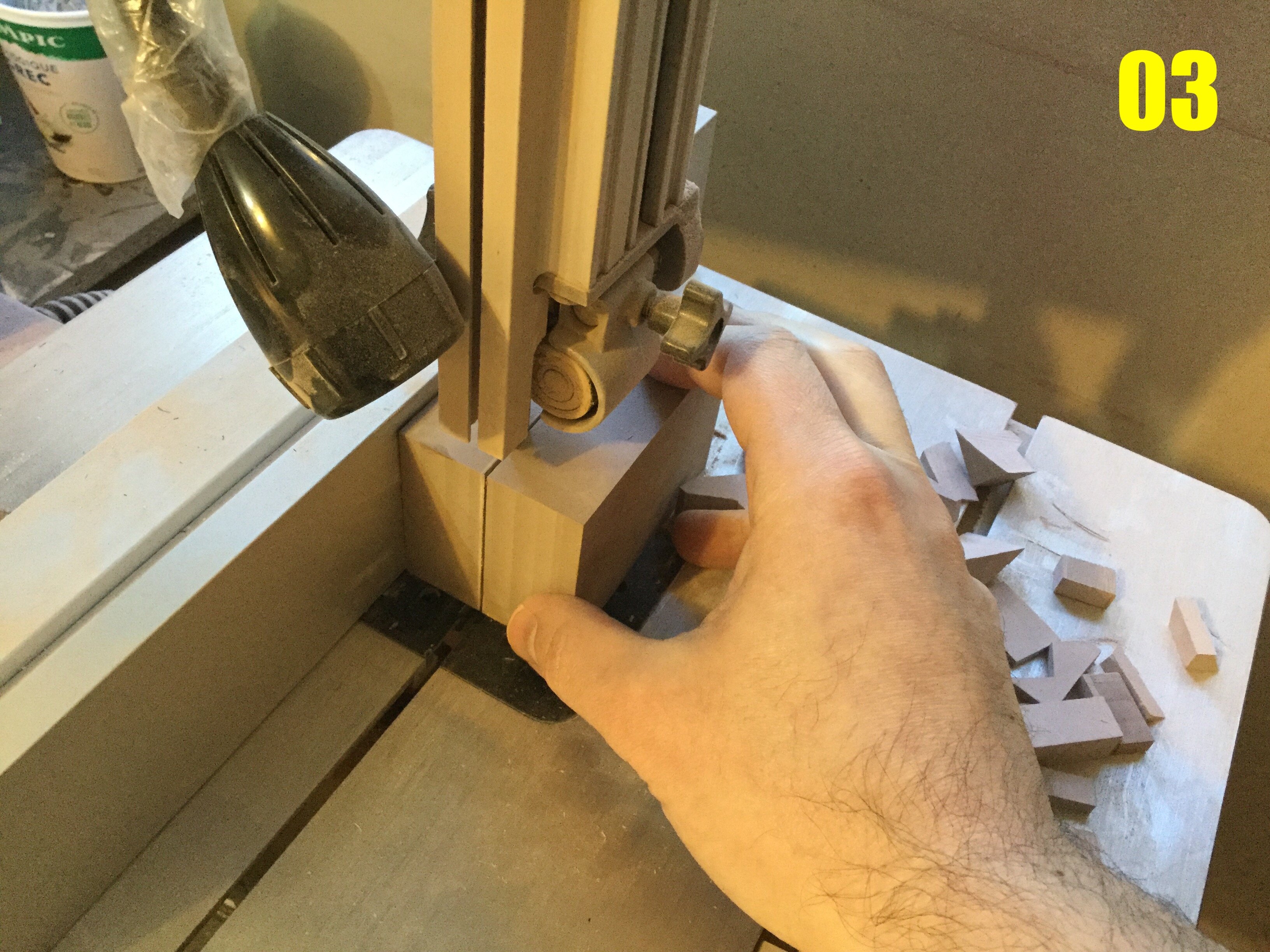
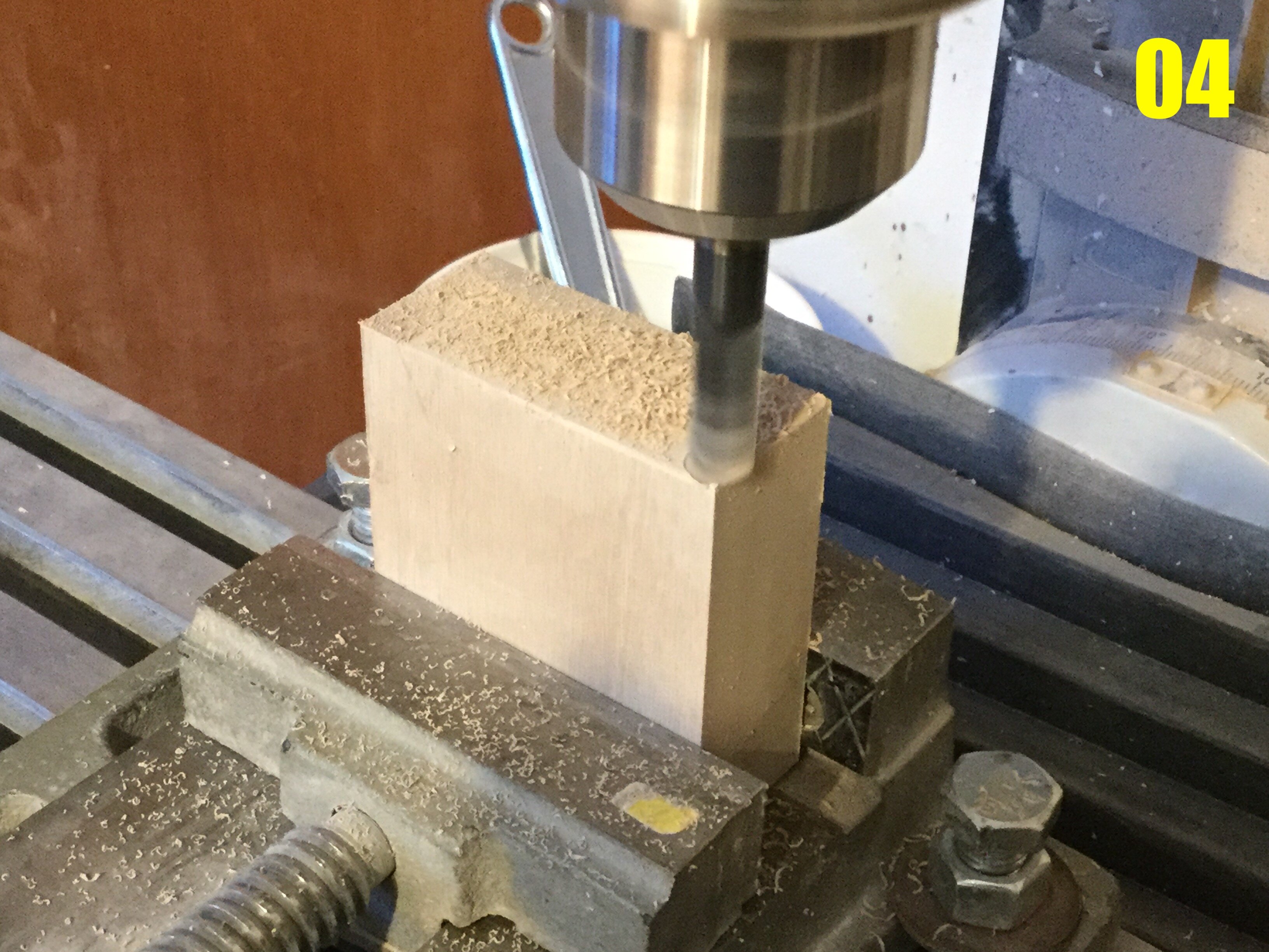
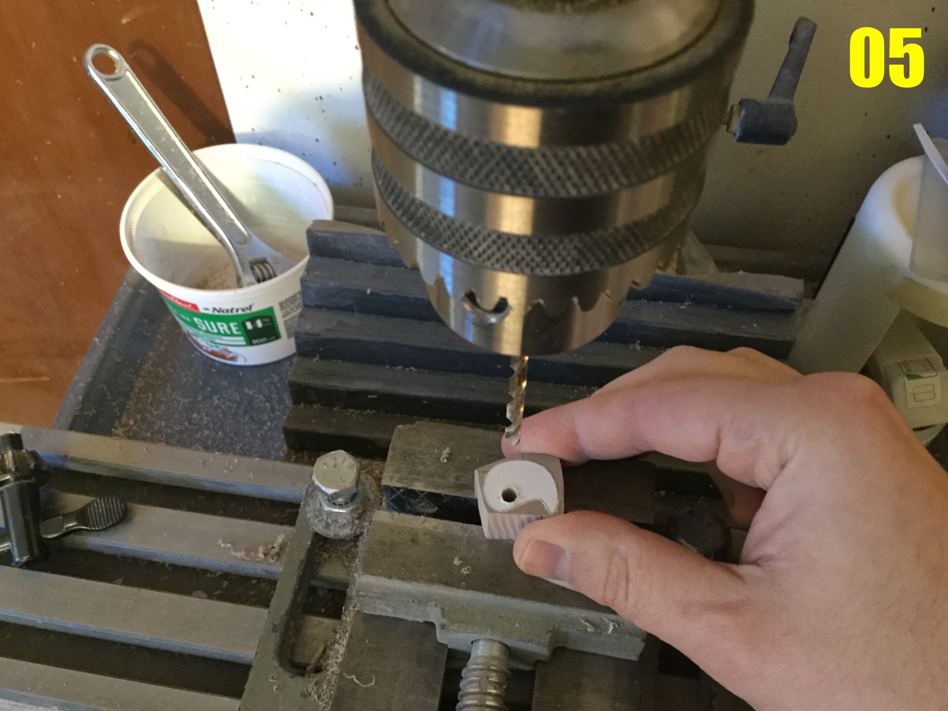
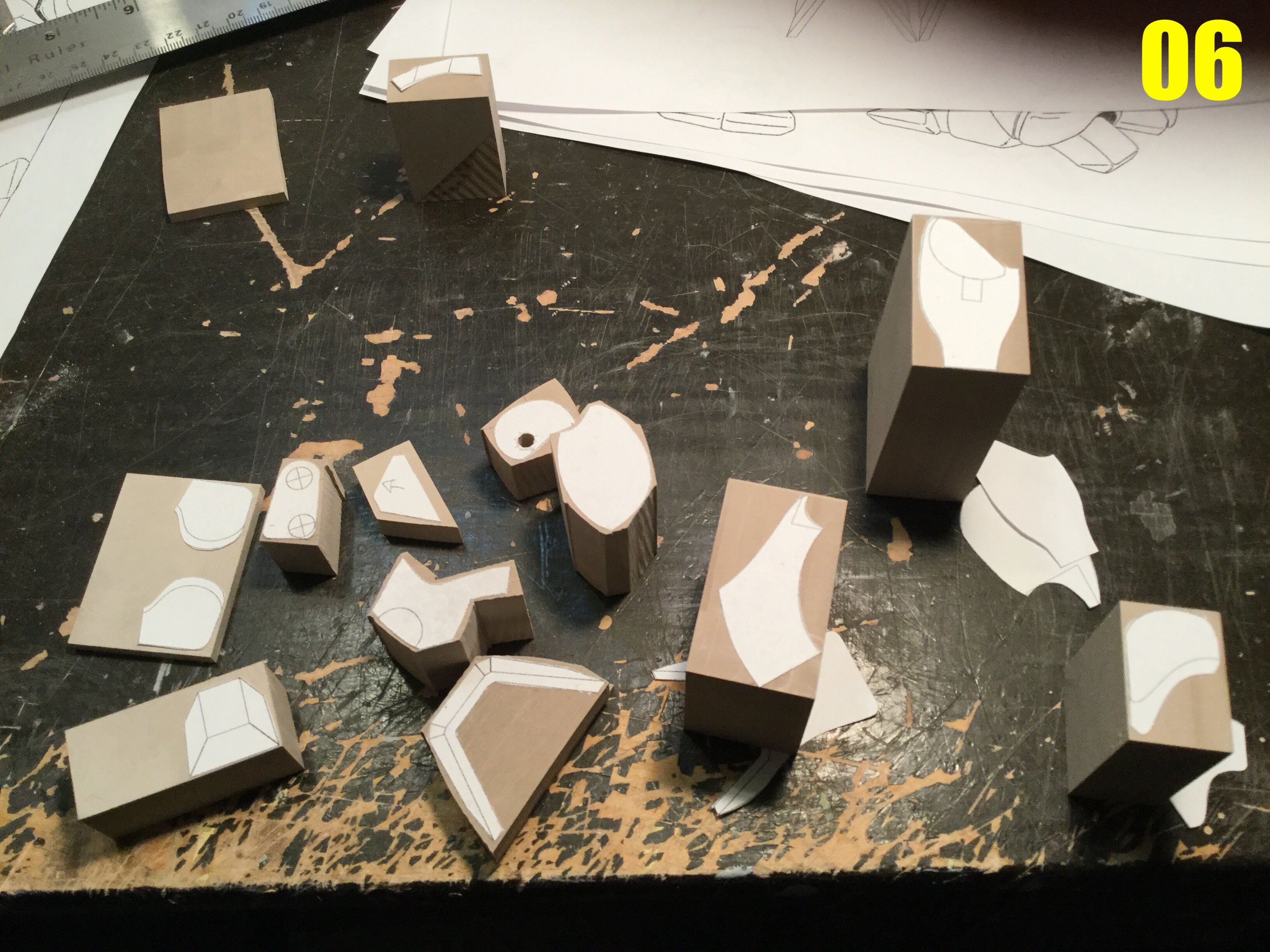
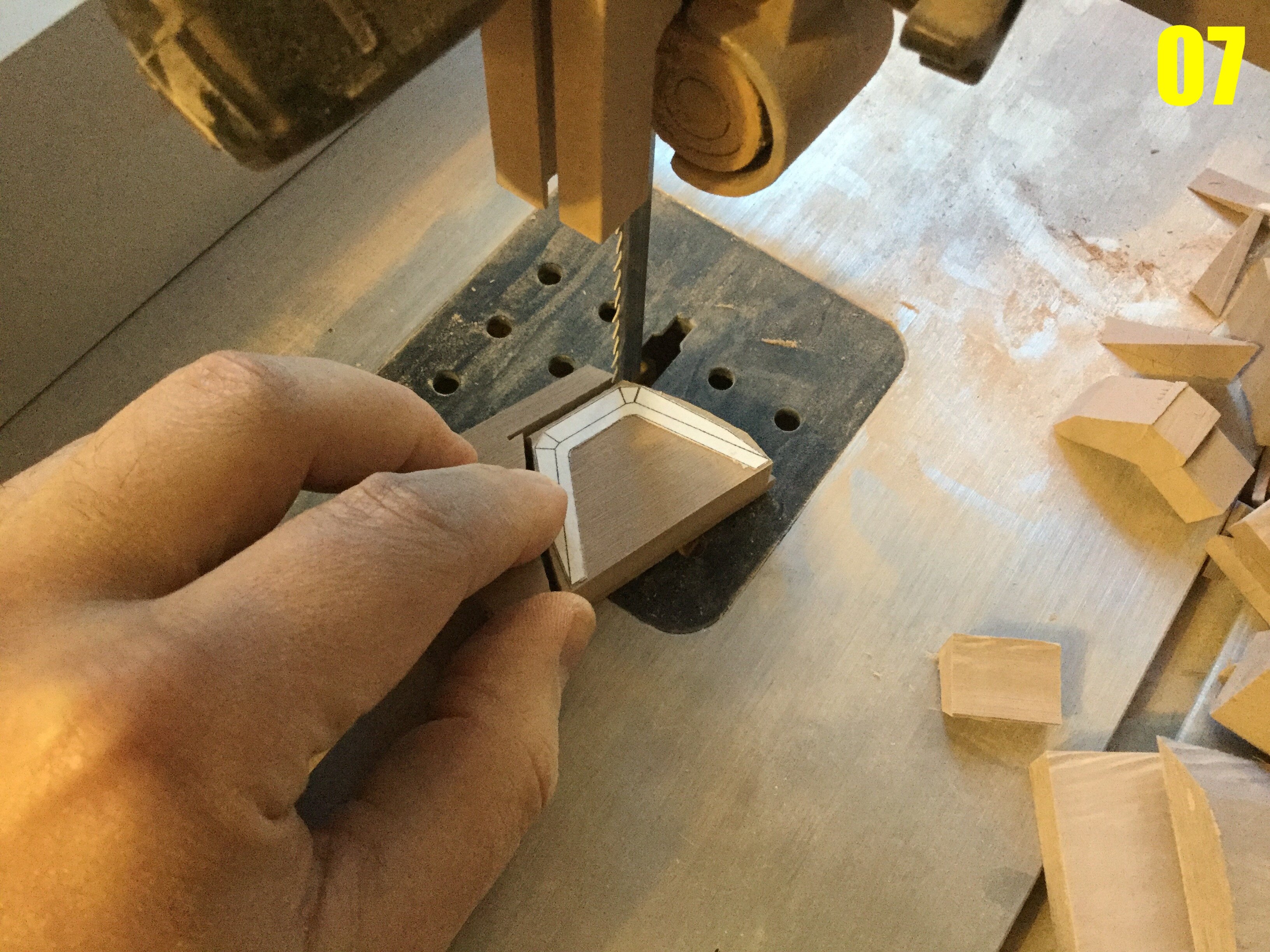
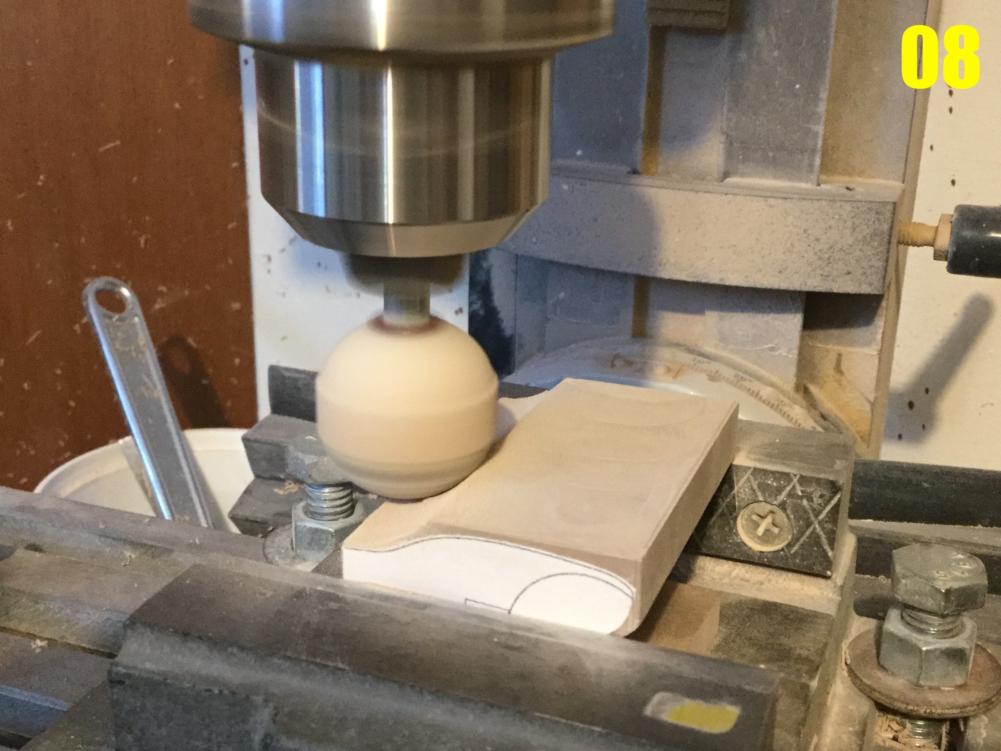
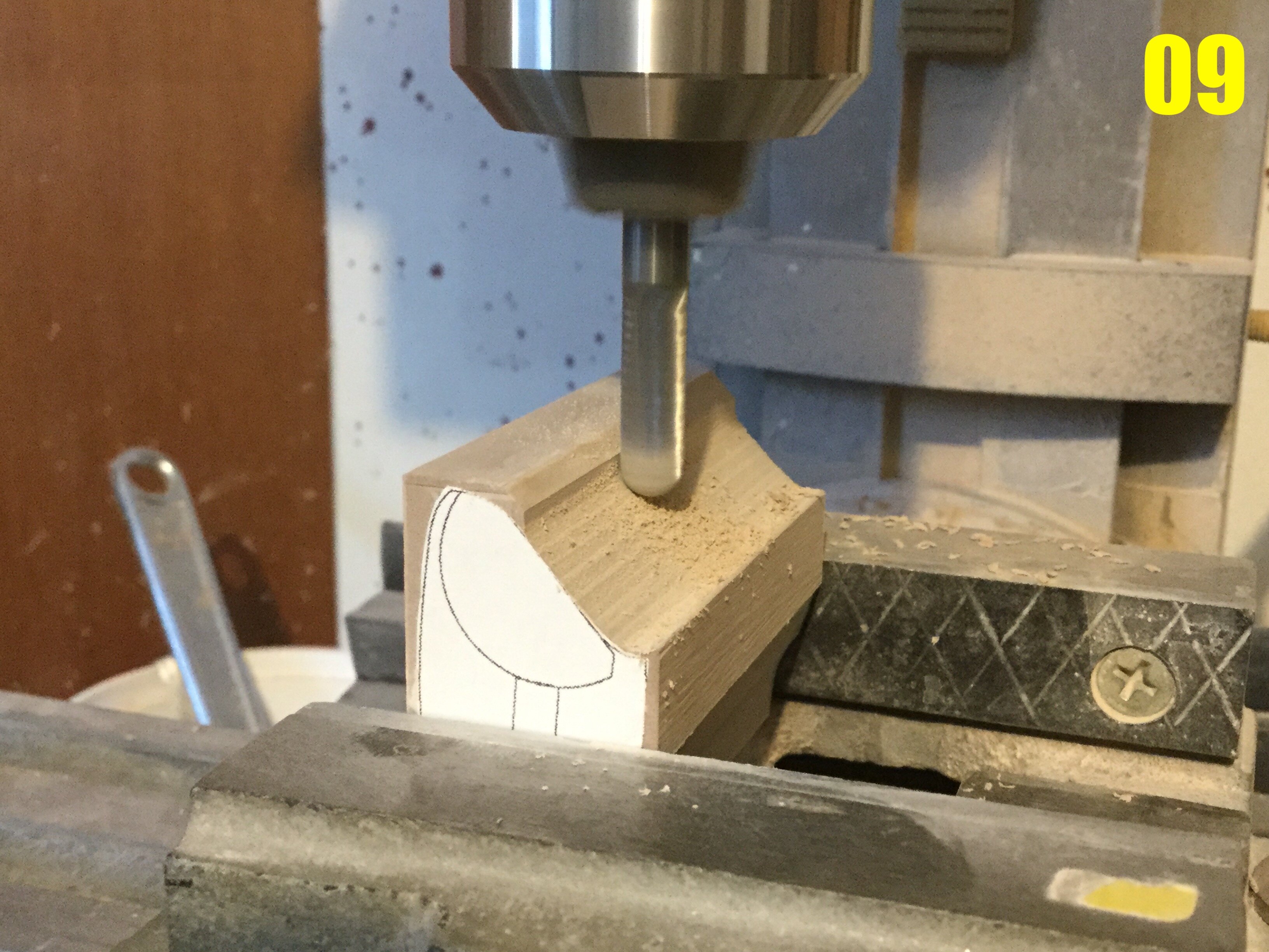
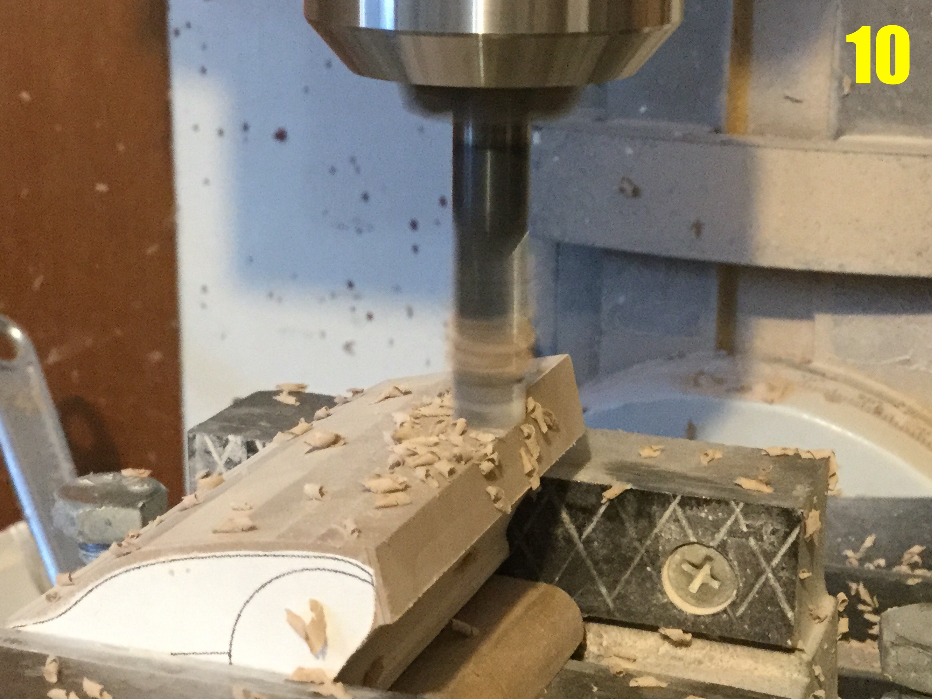
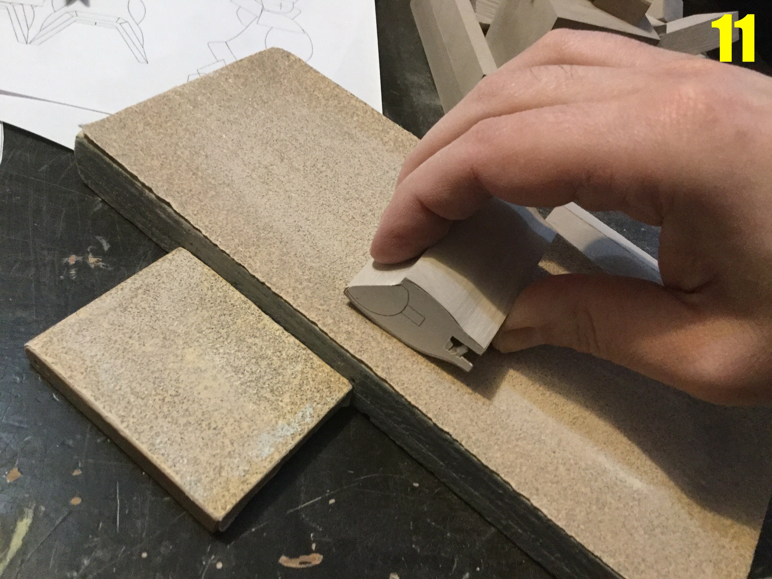
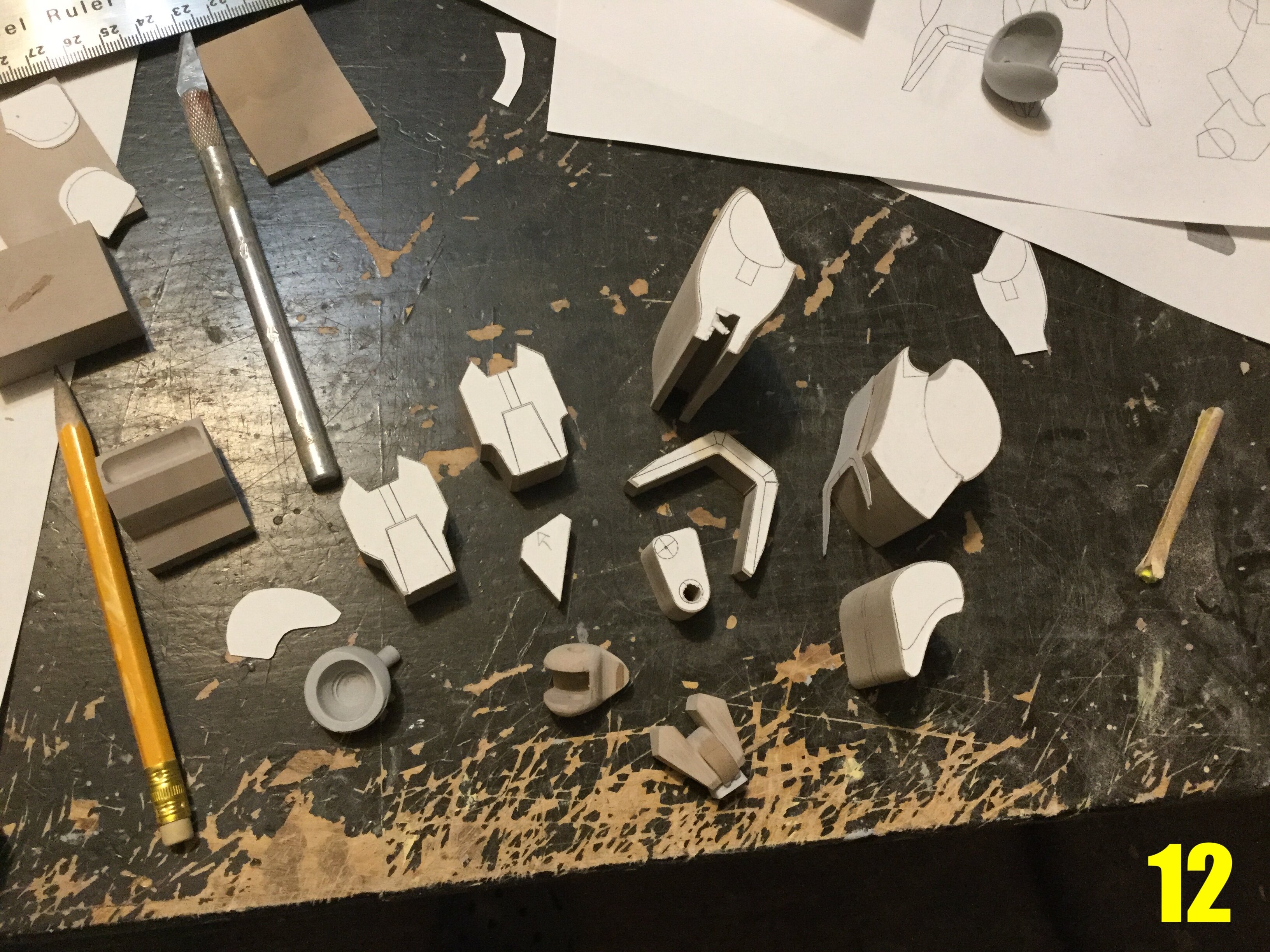
Captain’s log: Friday, January 14th. You may now send your payments, as construction has commenced on BIO LLOYD II. Take a look at pic 00. A really long, hard look. Now take a deep breath, and thank God that you’ll never have to pine or yearn for such a lackluster and uninspired sculpt ever again. Pic 01: in my own particular custom, now that the technical diagrams are (mostly) done, I can start making a mess in the shop. In addition to the schematics I made myself, I always have some copies of the original line-art on hand as reference. I also have some leftover blocks of modelling board from the last Bio Lloyd that will come in handy because they’re already squared and not too big. Pic 02: as per usual, I cut the paper templates out so that I can glue them to the blocks in order to guide the cutting and shaping process. Pic 03: … But first, some of the blocks need to be trimmed and made smaller. One particularity with these projects is that there are a myriad of small parts (blobs) which, when combined, will look like a mecha robot. Once a block is cut down to size, it then needs to go to the mill (pic 04) so that the roughly cut surface can be made smooth and square. however tedious this step is, it can’t be rushed: the accuracy with which the blocks are made will determine the accuracy of the final part and its fit with all the others. Pic 05: I’ve decided to create a new shoulder joint; something better than the MK I, so I start by drilling the peg hole that will serve as the shoulder pivot. This new, larger peg will be much sturdier. Pic 06: a number of templates have been glued to their respective blocks. This is really just the first phase, and some parts are so complex that they need a frontal and side template. Pic 07: with the templates in place, I proceed to remove as much rough material with the band saw as I can: this saves time and makes less of a mess than machining straight away. Pics 8-10: Because there are a multitude of curves in the parts to be shaped, I implement an array of different tools on the mill. Pic 8 shows a rarely used hack, which is to use a large grinding stone as a makeshift milling shank. Something like this would be unthinkable when working in metal, but because modelling board is easy to machine, I can implement this hack. Pics 10 and 11 show the use of more conventional milling shanks. I can expect to go through several different cutters on one part as a standard routine. Pic 11: the milling process can only go so far with some parts, so now that the vast majority of the excess material is removed, I can proceed to sand the parts manually for the final contouring. Pic 12: phase one of the parts shaping process has come along nicely. The plots you see in the upper-right corner are another reference I use to gauge my progress and make fit adjustments. Due to the… I will be polite… Very vague and incongruous reference material, I give myself the lattitude to make in-progress adjustments as I see fit, or to tweak the proportions to better match the 3/4 view of the mecha, which I esteem to be the prettiest. This first update is far from the most exciting, but the basic procedure laid-out for you is fundamental when employing classical scratchbuilding techniques. Things get more ineresting next week, so stay tuned!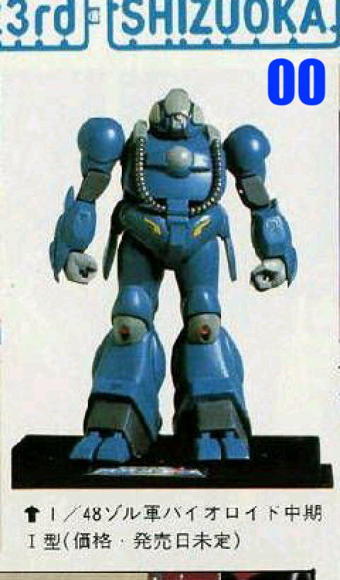
- 150 replies
-
- 2
-
-
- southern cross
- robotech
- (and 4 more)
-
1/48 SOUTHERN CROSS BIOROID PART II
captain america replied to captain america's topic in Anime or Science Fiction
It is! -
1/48 SOUTHERN CROSS BIOROID PART II
captain america replied to captain america's topic in Anime or Science Fiction
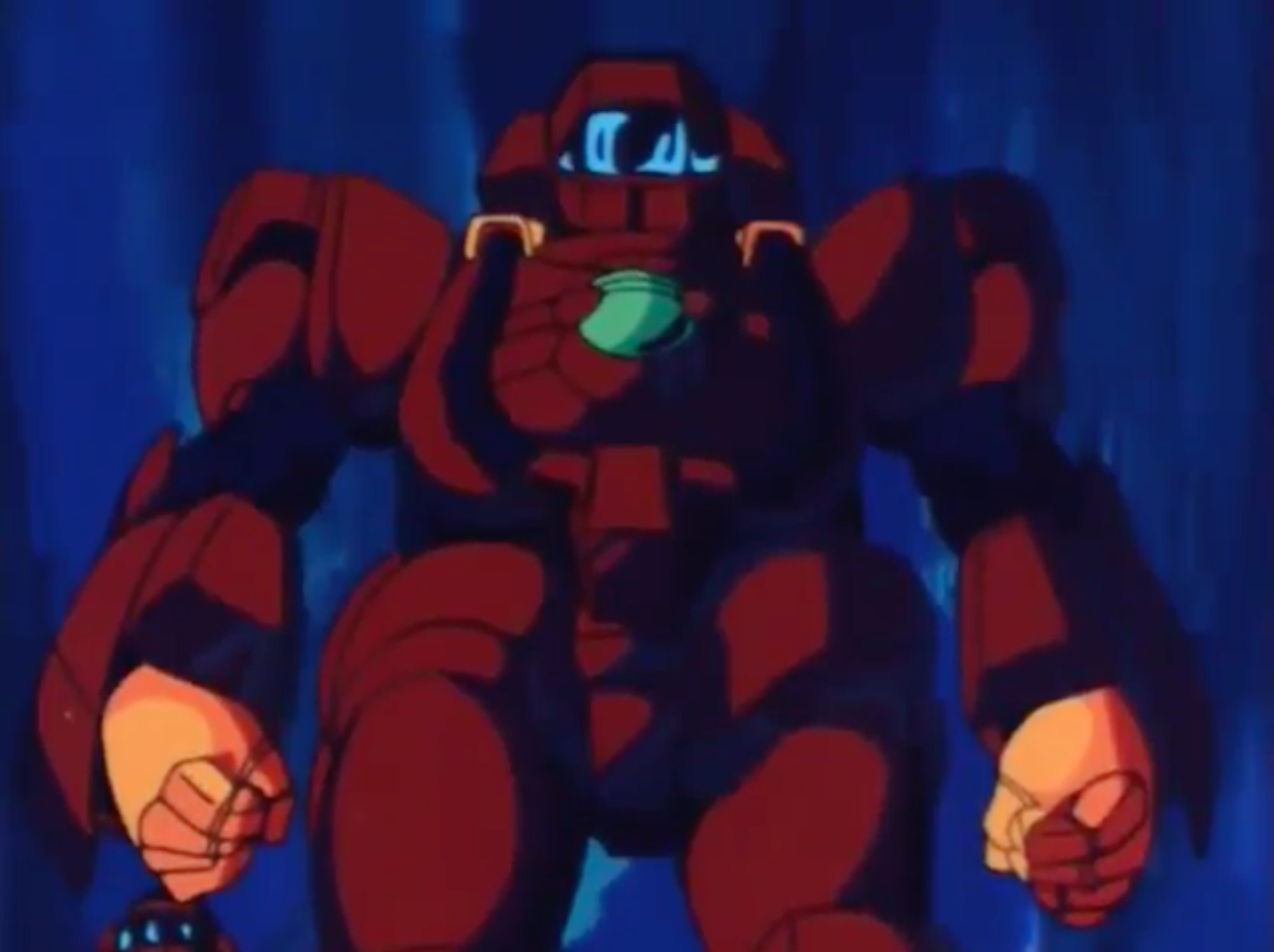
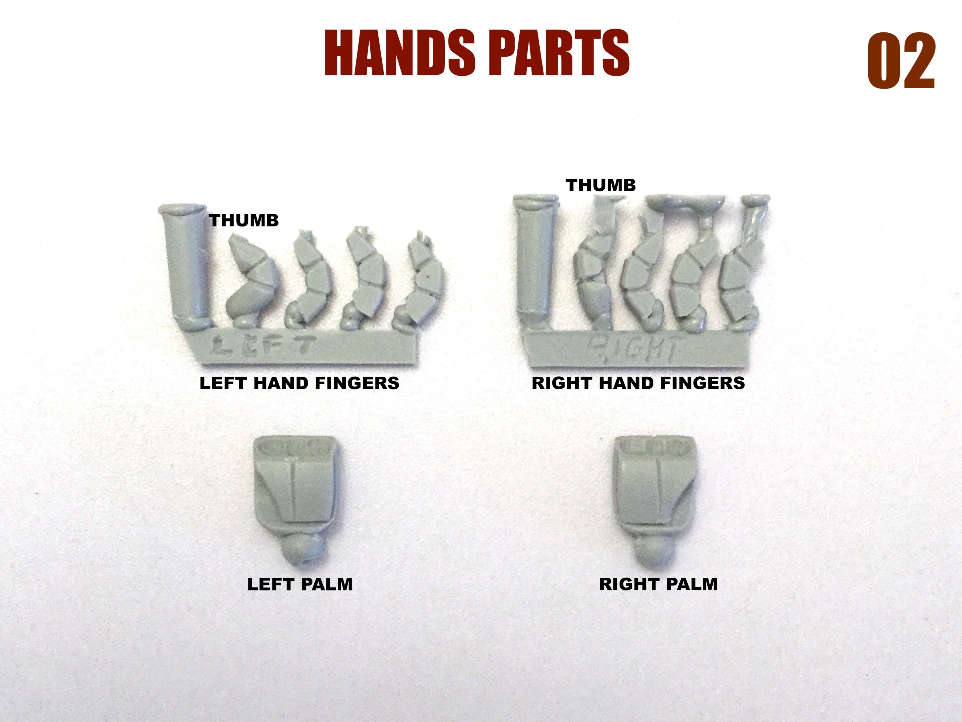
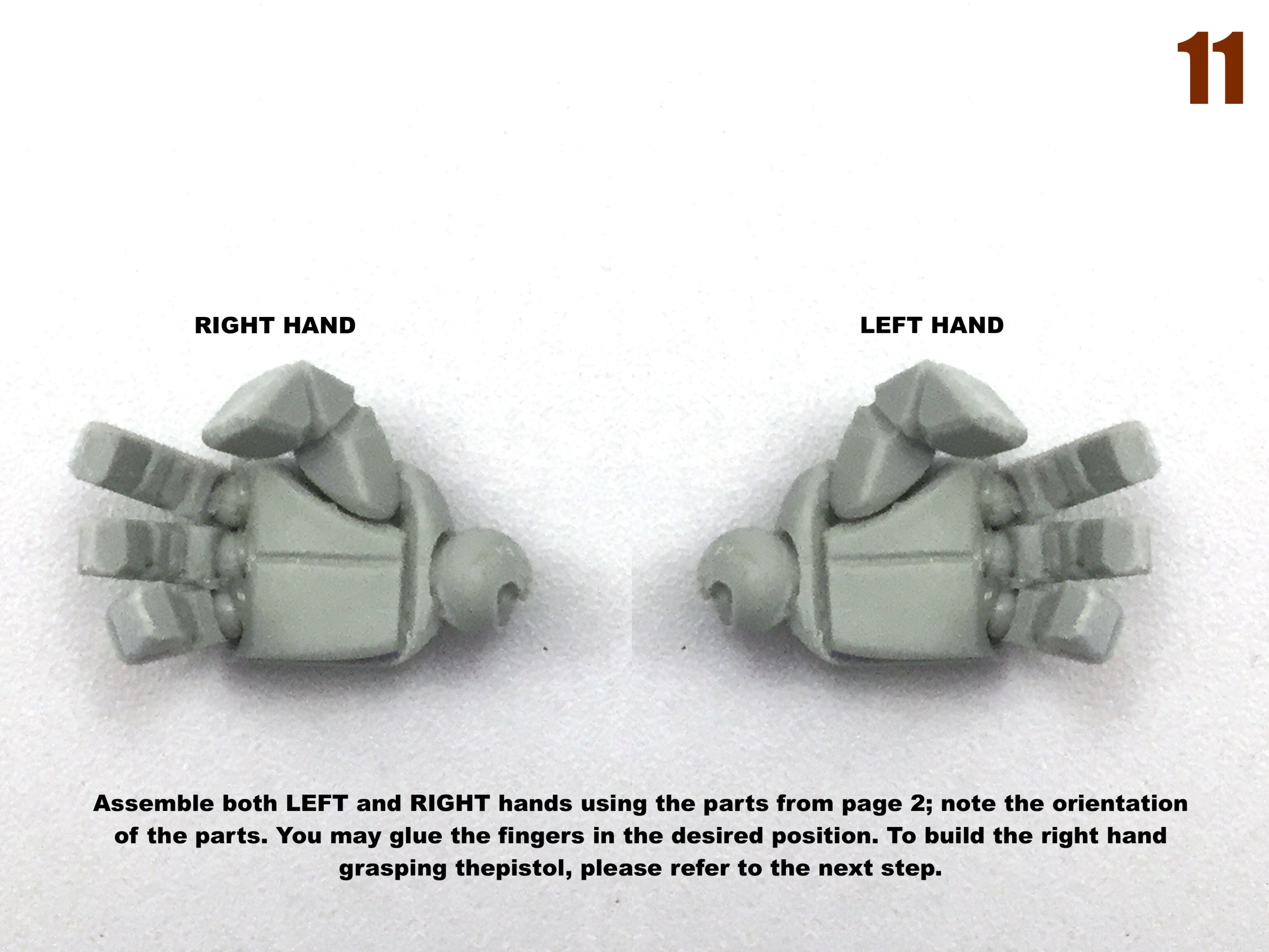
The wrist attachment will be the same as for Bio mk I. BUG FACE also appears to have 4 fingers, which makes sense, given how it's a derivative of the Biopsycher. -
1/48 SOUTHERN CROSS BIOROID PART II
captain america replied to captain america's topic in Anime or Science Fiction
The resolution on the line-art I had wasn't high enough to determine the finger count, which is why I resorted to the animation. -
1/48 SOUTHERN CROSS BIOROID PART II
captain america replied to captain america's topic in Anime or Science Fiction
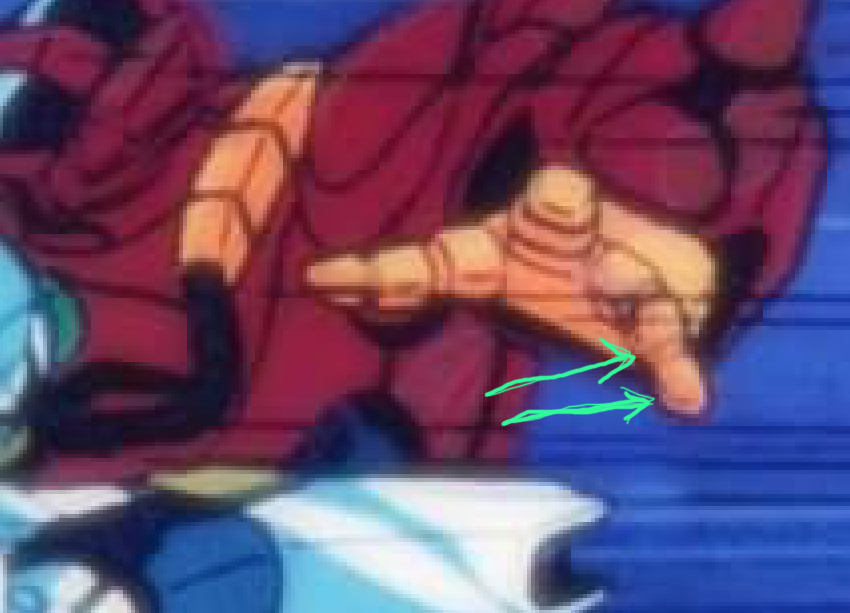
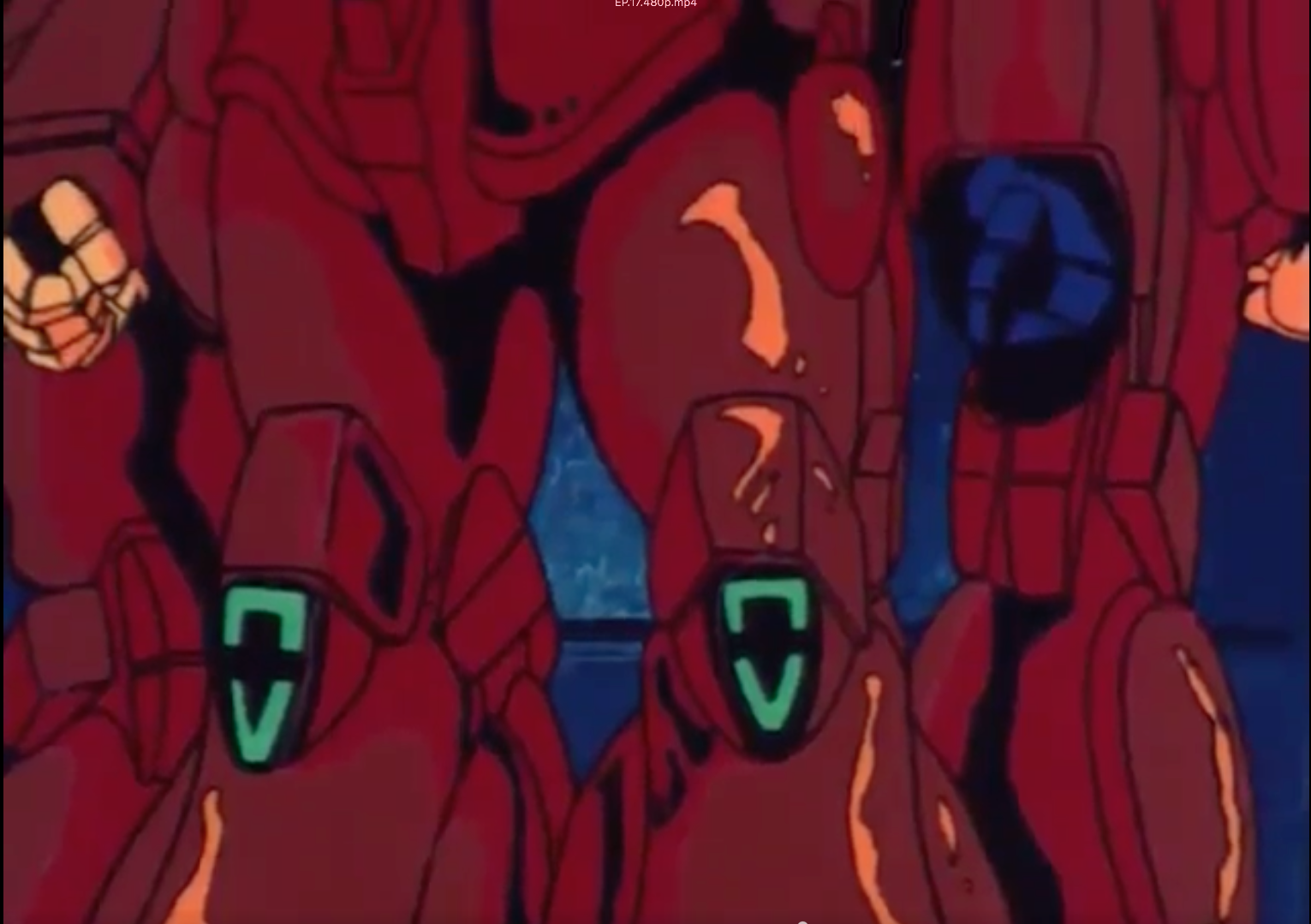
You can actually see it if you scrutinize the Biopsycher's left hand carefully. Admittedly the resolution doesn't help, but there are actually four fingers plus the thumb. When you combine that shot with these two other shots, you see that there are indeed 5 fingers and not three. Re-using the Bio-Llloyd hands would have been the preferable option, but these images dictate otherwise.