

captain america
-
Posts
3549 -
Joined
-
Last visited
Content Type
Profiles
Forums
Events
Gallery
Everything posted by captain america
-
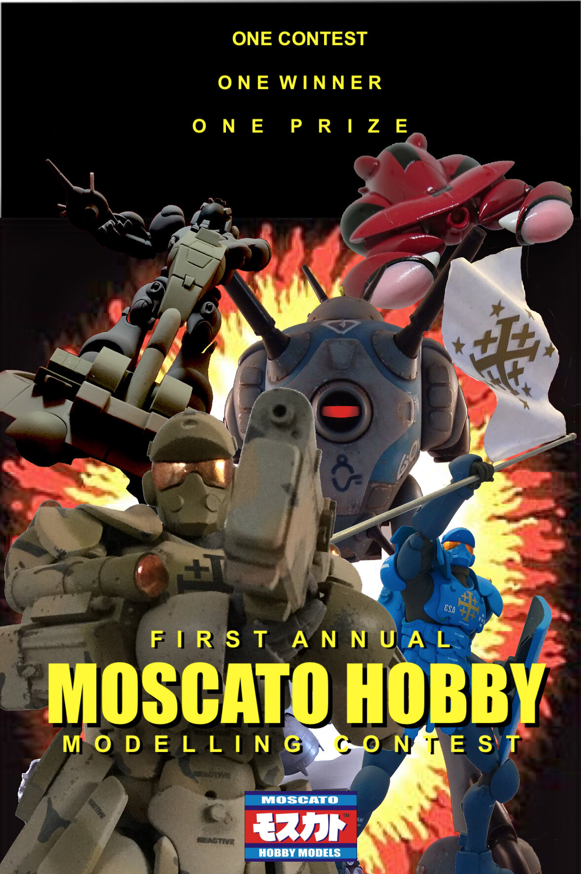
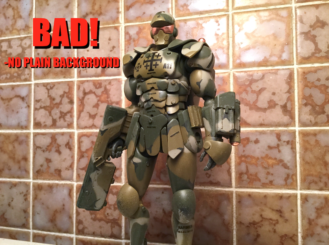
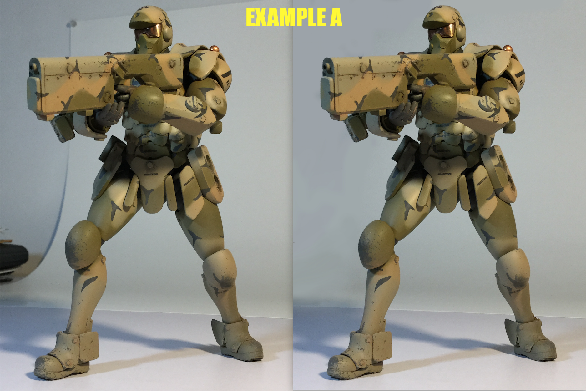
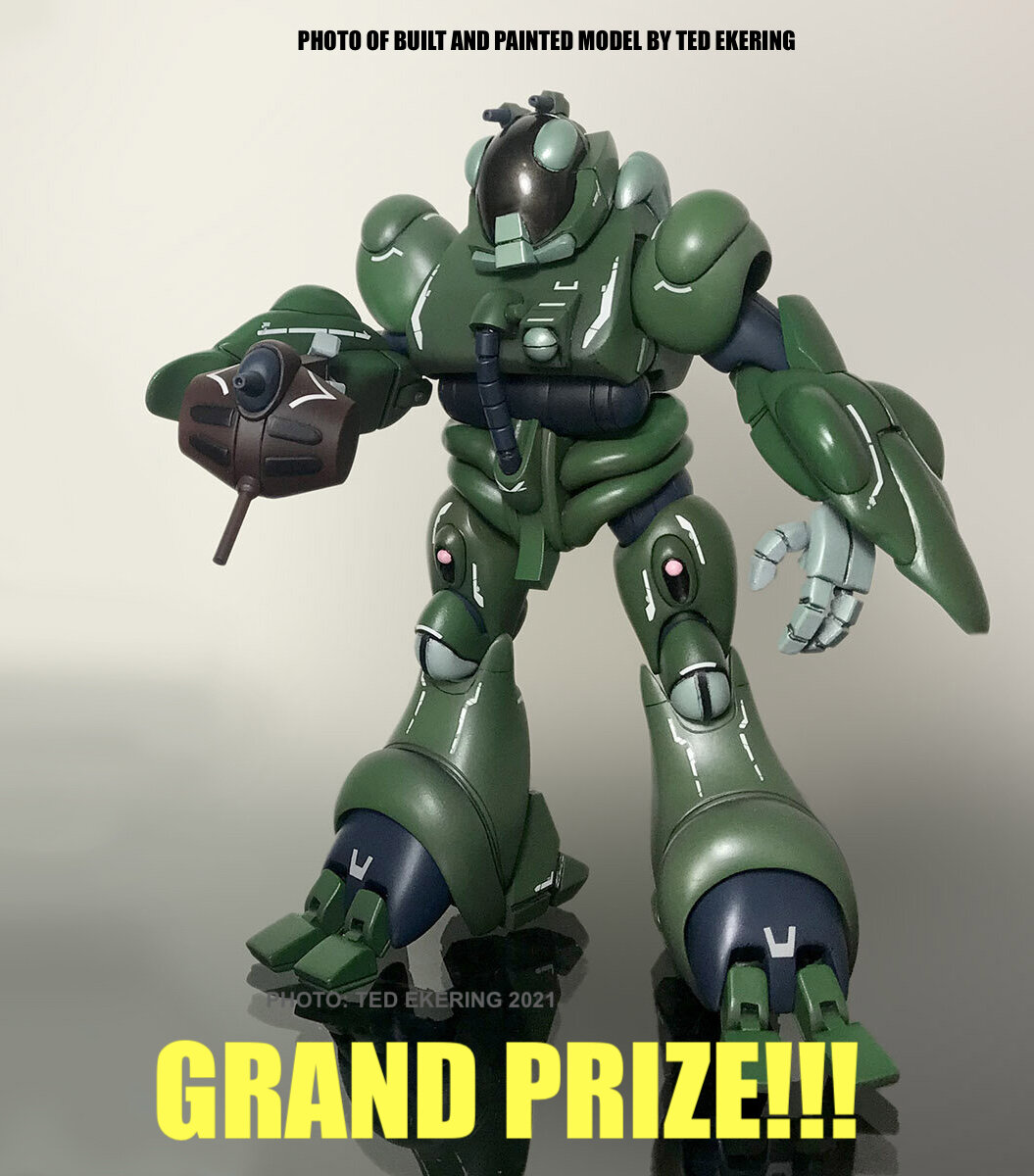
***CONTEST RULES*** -The contest will take place from September 13th to December 13th, 2021, and we will be accepting entries immediately on September 13th, if you have something ready. Last-minute entries are welcomed, so long as you respect the deadline date and time -The kit you enter must be an original Moscato Hobby Models kit. Any scale, any subject -The kit can have been built at any time in the past, so already completed kits are welcome -Modifications are welcome, even extensive ones -Two entries maximum per person -Three (3) photos per entry maximum -For judging purposes, there should only be one subject per photo -Models should be photographed against a plain, neutral background of any solid color. Even sonething as simple as a white sheet of paper or cardboard will suffice. Models photographed against a backdrop featuring your stash, your messy bedroom, your cat, etc. will be disqualified -Bribery will be grounds for disqualification! -Dioramas and vignettes are welcome also. The entire dio will be considered one subject, even if there are multiple models in the scene -Photo-editing is only permitted to adjust color balance, or blank-out the background; see EXAMPLE A -please include a watermark or your name somewhere in the photo to avoid someone stealing or passing your pic off as their own. If this exceeds your skill level or you forget, I will add your name to the pic before publishing it -Since this is the very first contest of this kind, you may use any photos you’ve taken in the past. However, take note that should there be other such contests in the following years, the photos previously submitted will no longer be eligible. Therefore, if you decide to enter the same kit/subject a following year, you will need to take new photos -The deadline for entres is December 13th, 2021 9pm EST. The winner will be announced on Dec 17th, 2021 -Each subject submitted should include a brief description: kit name, scale, and a short description of any notable modifications (60 words tops) example: «1/48 Pinky Space Crab. Kit has been modified with aftermarket ball-joints for posability, and an integrated battery and LED for the mono-eye. The beam guns are also removable with magnets. Kit was finished with Mr. Color lacqer paints. The primary color was obtained by mixing 50% H-X and H-Y and H-Z was used for the pink. » JUDGING CRITERIA Because this is an on-line contest whereby the actual kits cannot be meticulousy scrutinized with dental mirrors, actual anime or military paint swatches, and electron-beam microscopes, the judging will be based on the overall « wow » factor of the image. Each subject will be awarded points on the following criteria: -the overall build and finish quality of the model based on the photographs provided 1-10 points -MECHA ONLY- the pose or positioning of the model: does the pose of the mecha look clumsy or natural? 1-10 points -AIR/SPACECRAFT ONLY- does the angle at which the model is photographed look dynamic, or show-off its best features? 1-10 points -DIORAMA/VIGNETTE ONLY- overall composition, layout. Is it a productive use of space? 1-10 points divided between the mecha, ship/aircraft, figures, surroundings, depending on the elements included -photo quality: is the subject well or cleverly lit? Are the photos clear or blurry? Does the suject get confused with the background because the colors are too similar? 1-5 points -creativity: have you done something special to the model that makes it more impressive, like add lights, modify the pose, scratchbuild or replace meticulous parts for added realism? 1-5 points Total of 30 points possible per subject (10 for overall build quality, 10 for its category, 5 for photo, and 5 for creativity) WHO WILL JUDGE THE ENTRIES? -Myself (John), Brett from Return2KitForm, and his wife Chrissy will serve as judges. HOW DO I SUBMIT MY ENTRY? Just send a private message to me on the MHM Facebook page with your images and desired text. I will process your entry and then publish it in a special folder entitled 2021 MHM CONTEST, which will be accessible when you browse the image folders on my page. GRAND PRIZE There is only one winner, and one prize, which will be a 1/48 Moscato Hobby Jolly Green Bio Lloyd unassembled resin kit. Some Q & A clarifications Would a subject (or diorama) photographed against a real sky background be acceptable? Yes! I will ammend the rules to reflect this clarification. I'll allow it for dioramas/vignettes, since their purpose is to show models in an environment. Could said diorama include models (or toys) that weren't Moscato products? Yes, so long as the models/toys/tree products, rocks, etc. Are not the focal point of the diorama. As long as a Moscato kit is the main subject, the other, decorative props are fine. I imagine something like this is out of the question, then...? Correct. I want the physical model to be as clearly visible as possible, so while I enjoy lens flares and muzzle flashes and things of that sort, not for this competition. That said, I would be happy to have the modeller show-off those extra effects in a side-by-side pic without the digital bells and whistles after the competition is over. How about, say, a pose that required the support of a stand? Could the stand be edited out of the photograph(s)? Yes, the stand can be edited out. That actually falls under the umbrella of EXAMPLE A, where some cluttering elements can be digitally removed. How about extortion, kidnapping, or blackmail...? 😄 Love me a challenge!
-

MOSPEADA HORIZONT in 1/350?
captain america replied to captain america's topic in Anime or Science Fiction
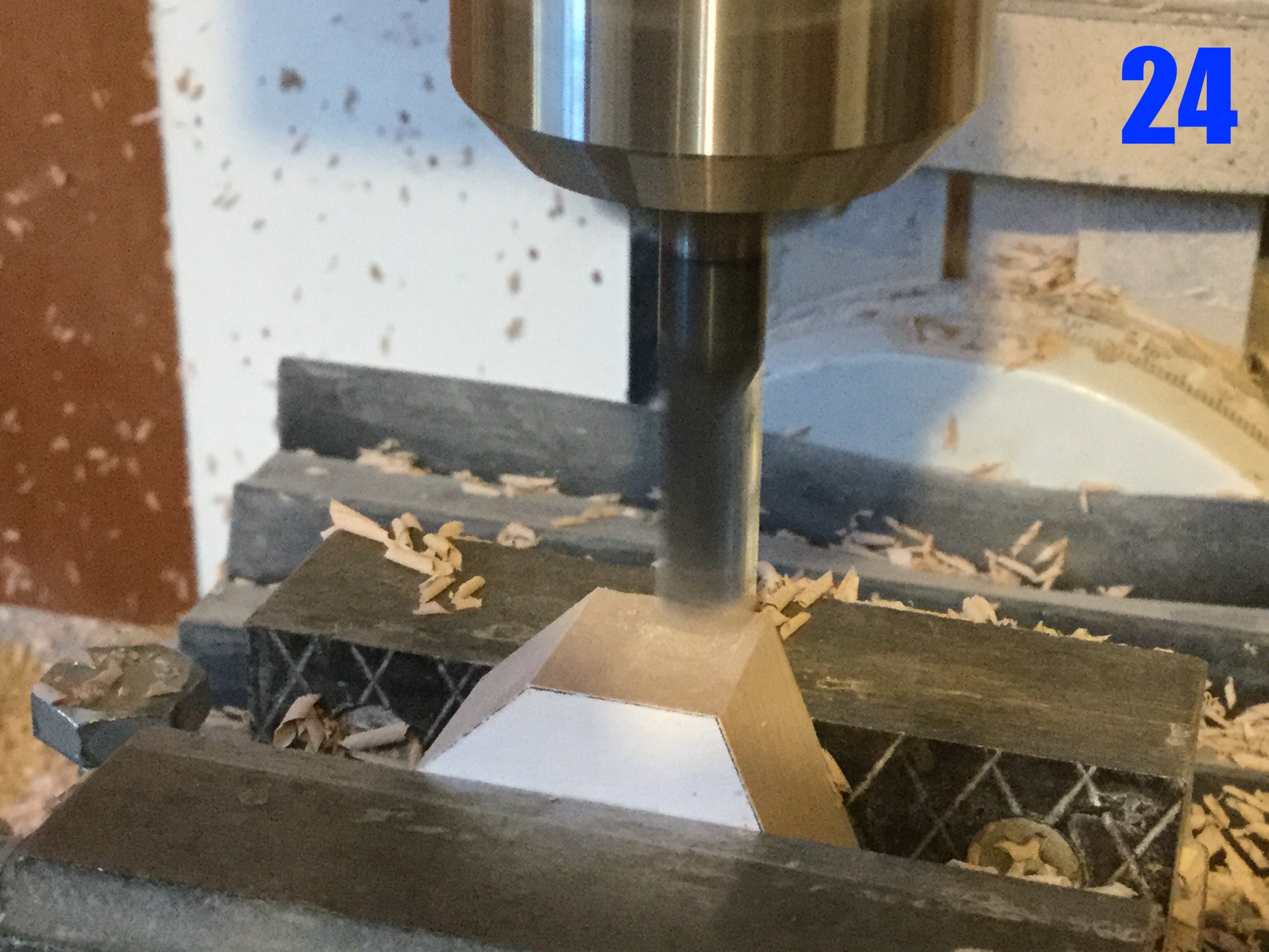
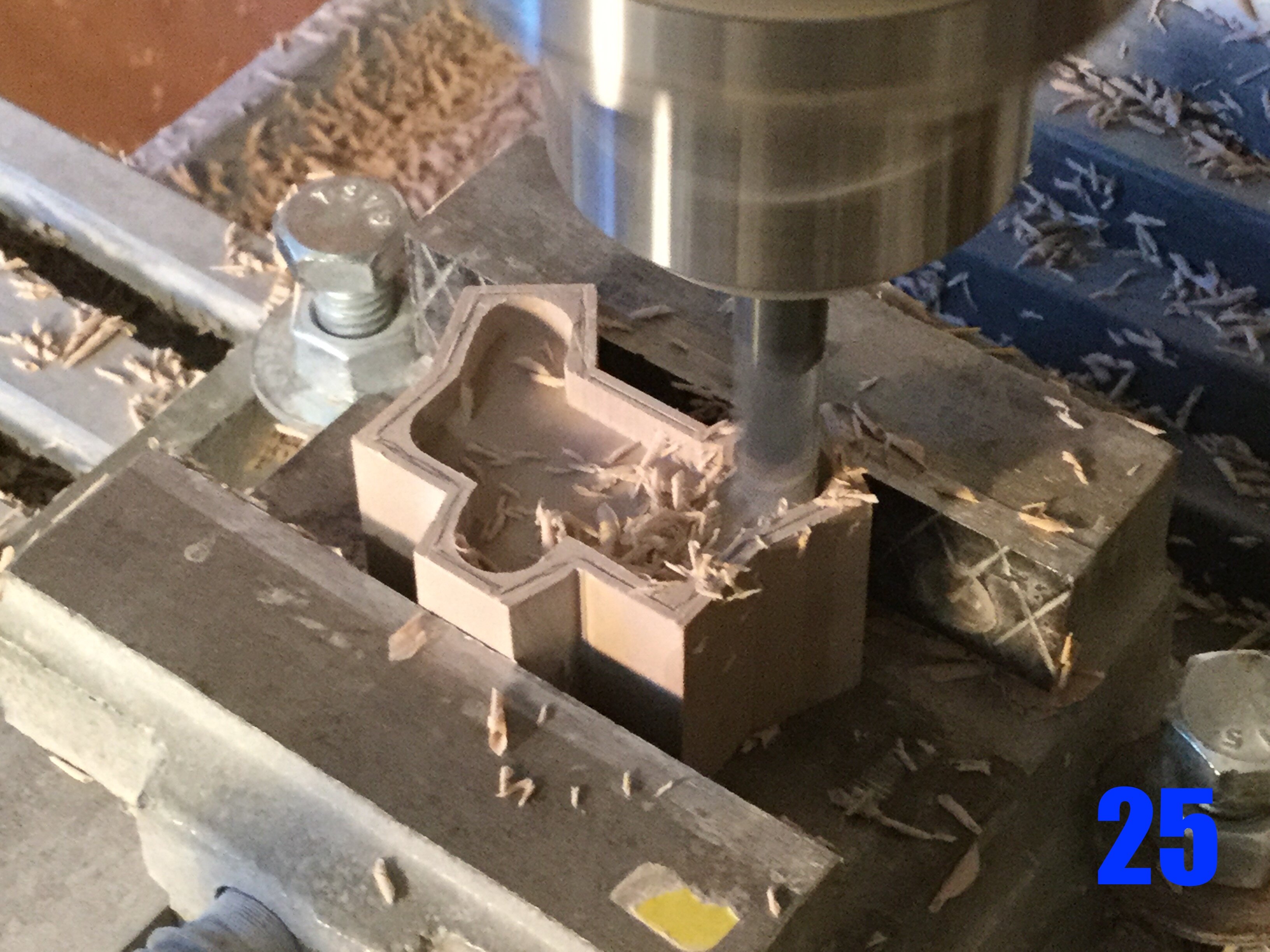
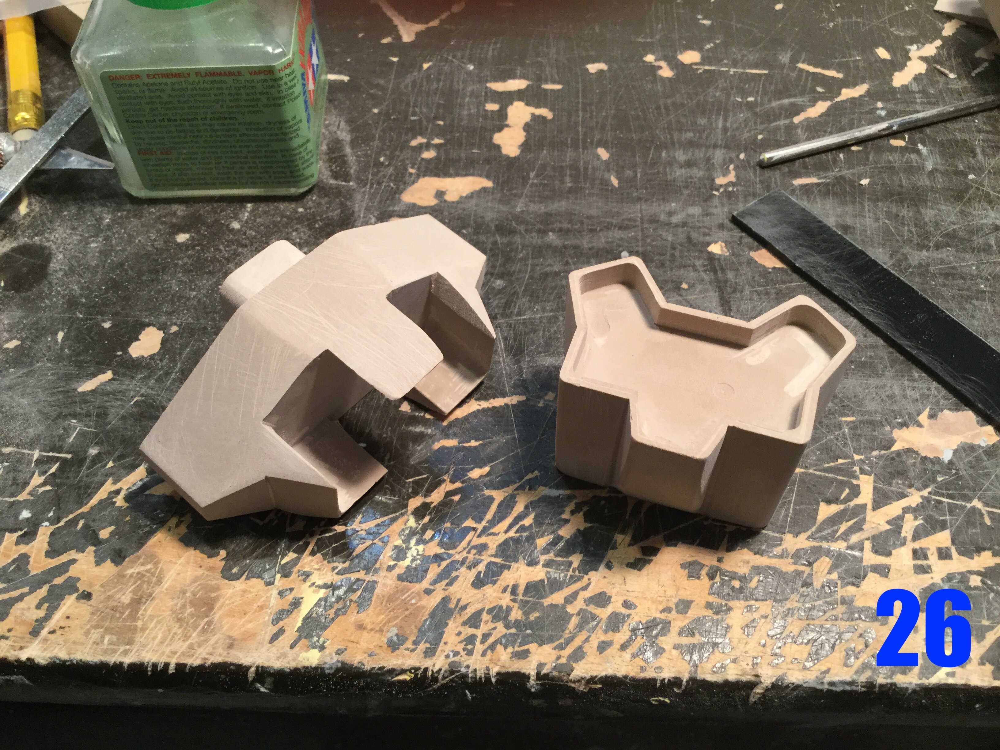
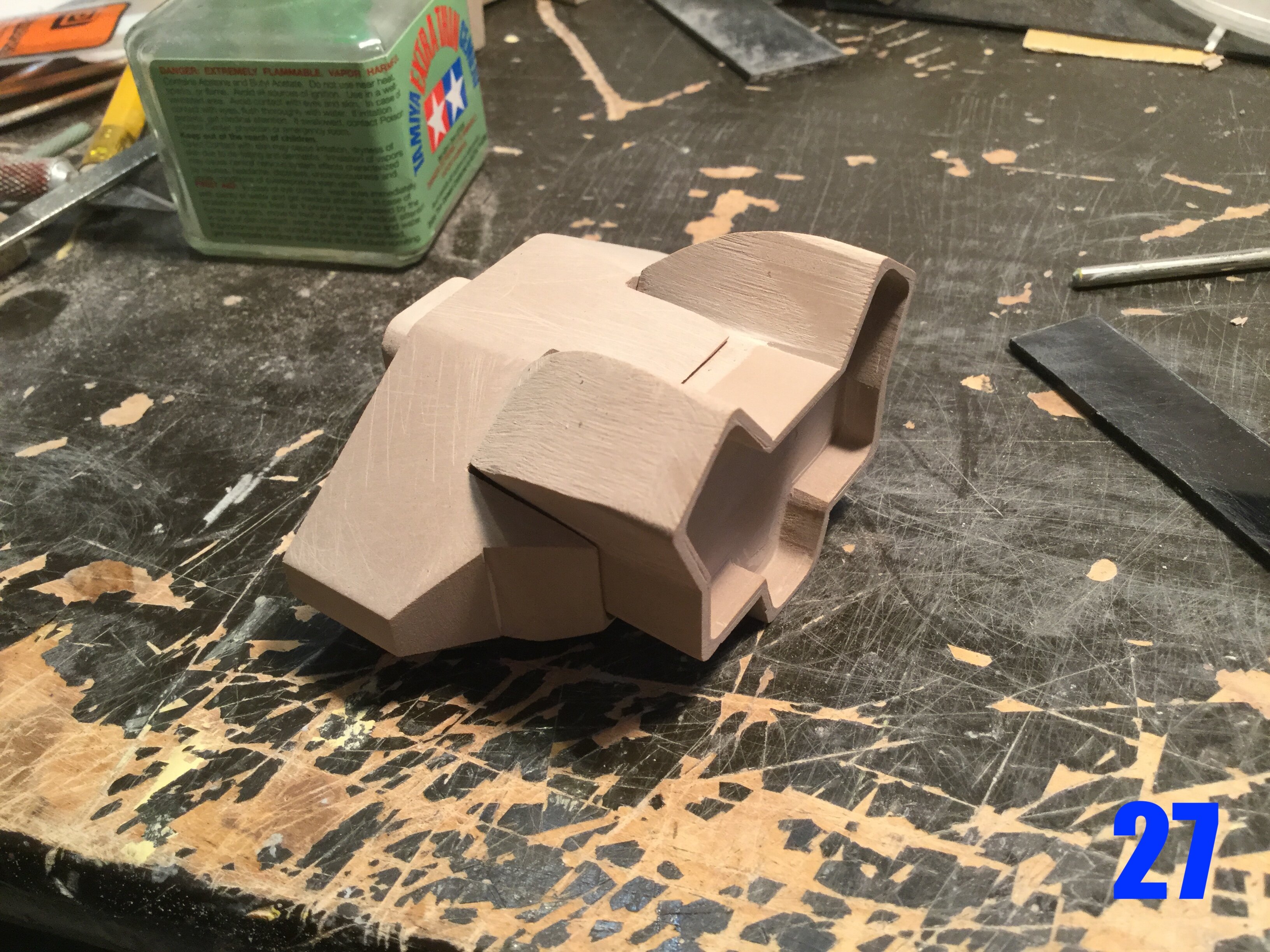
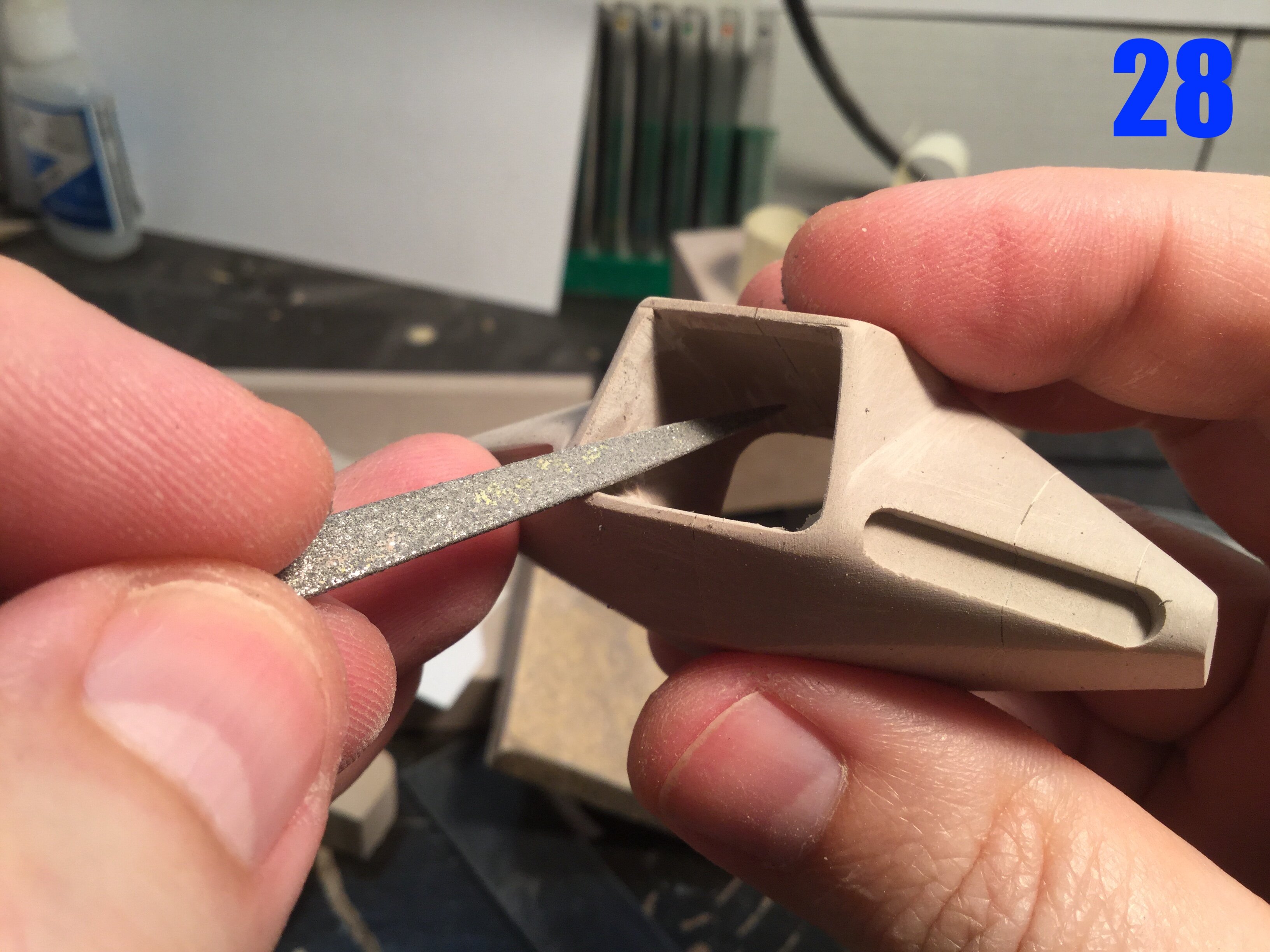
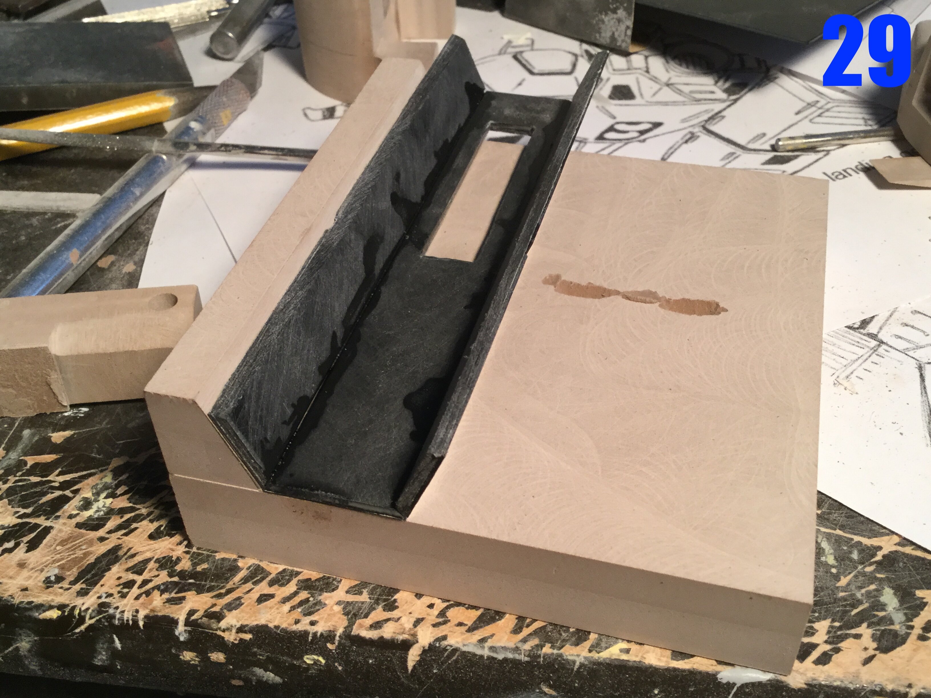
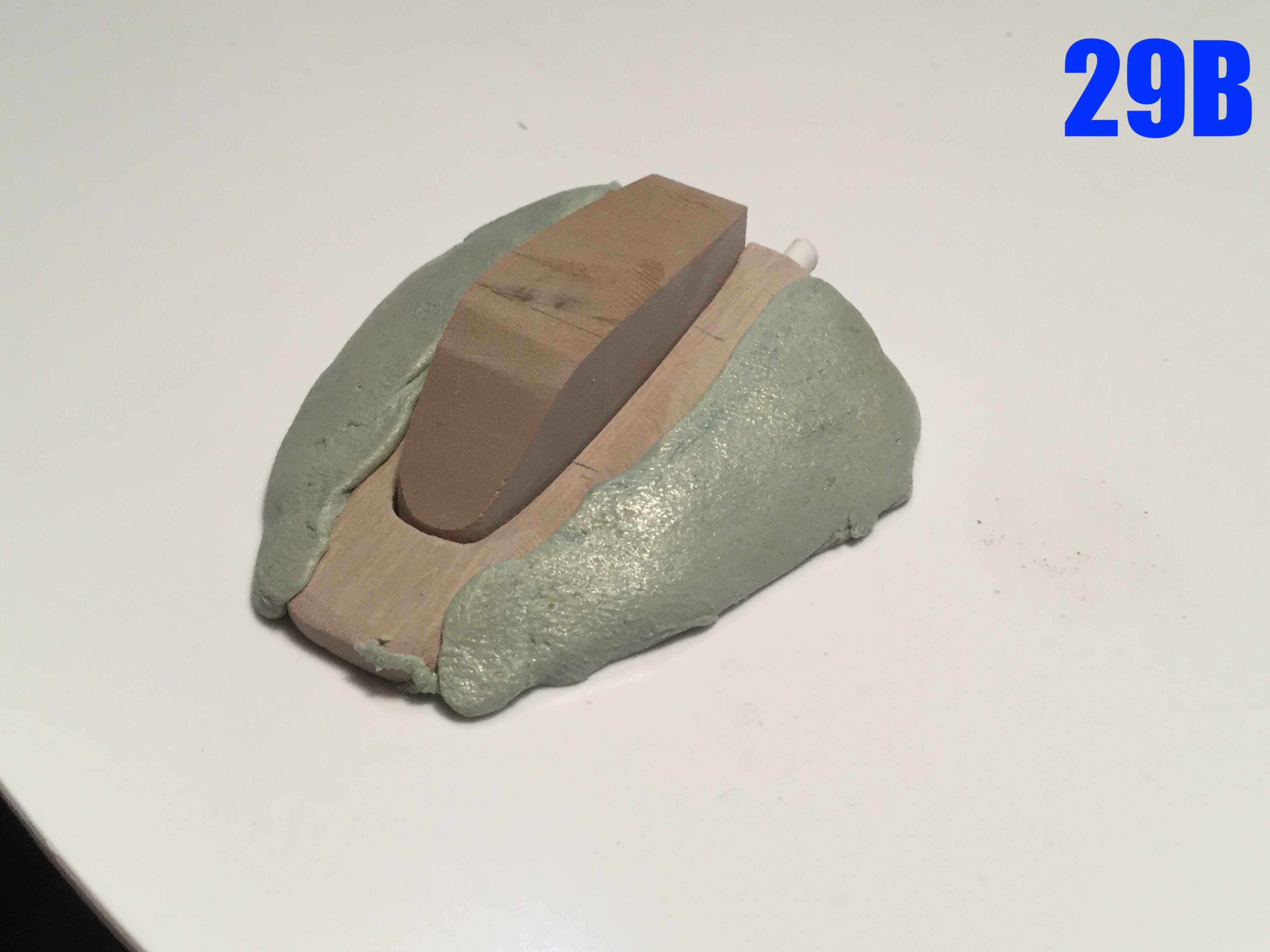
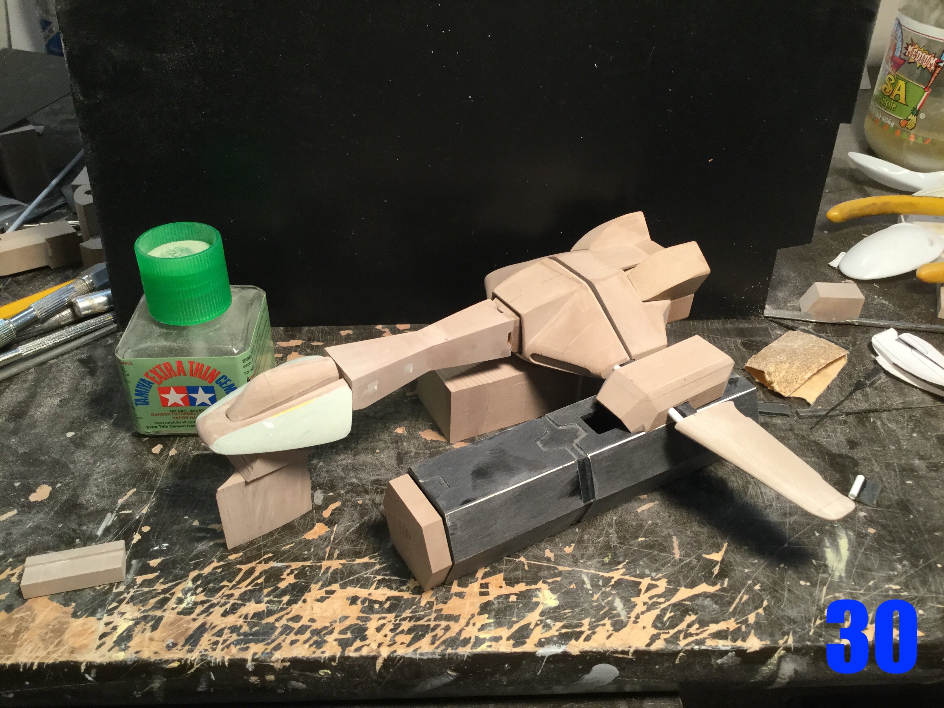
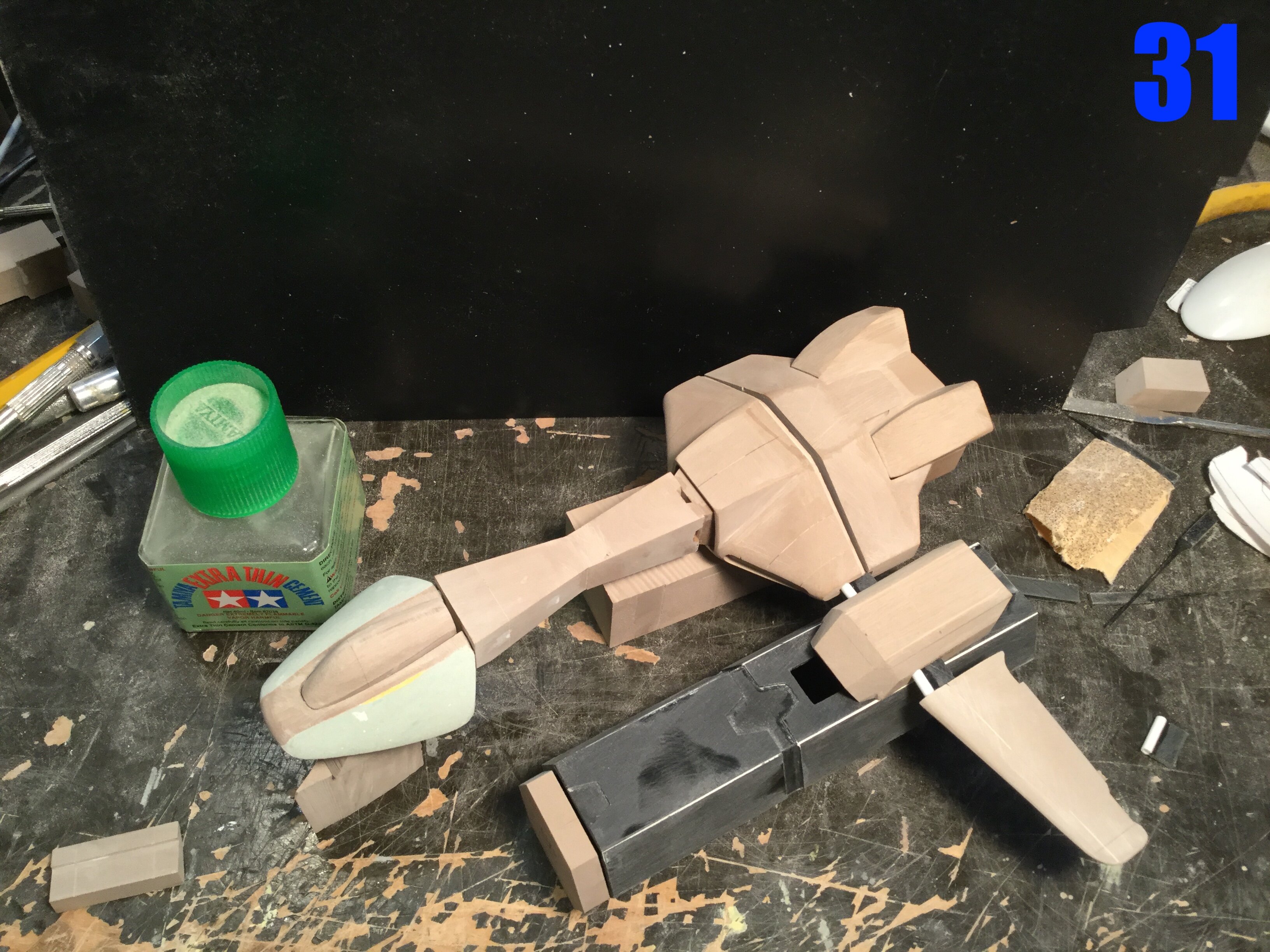
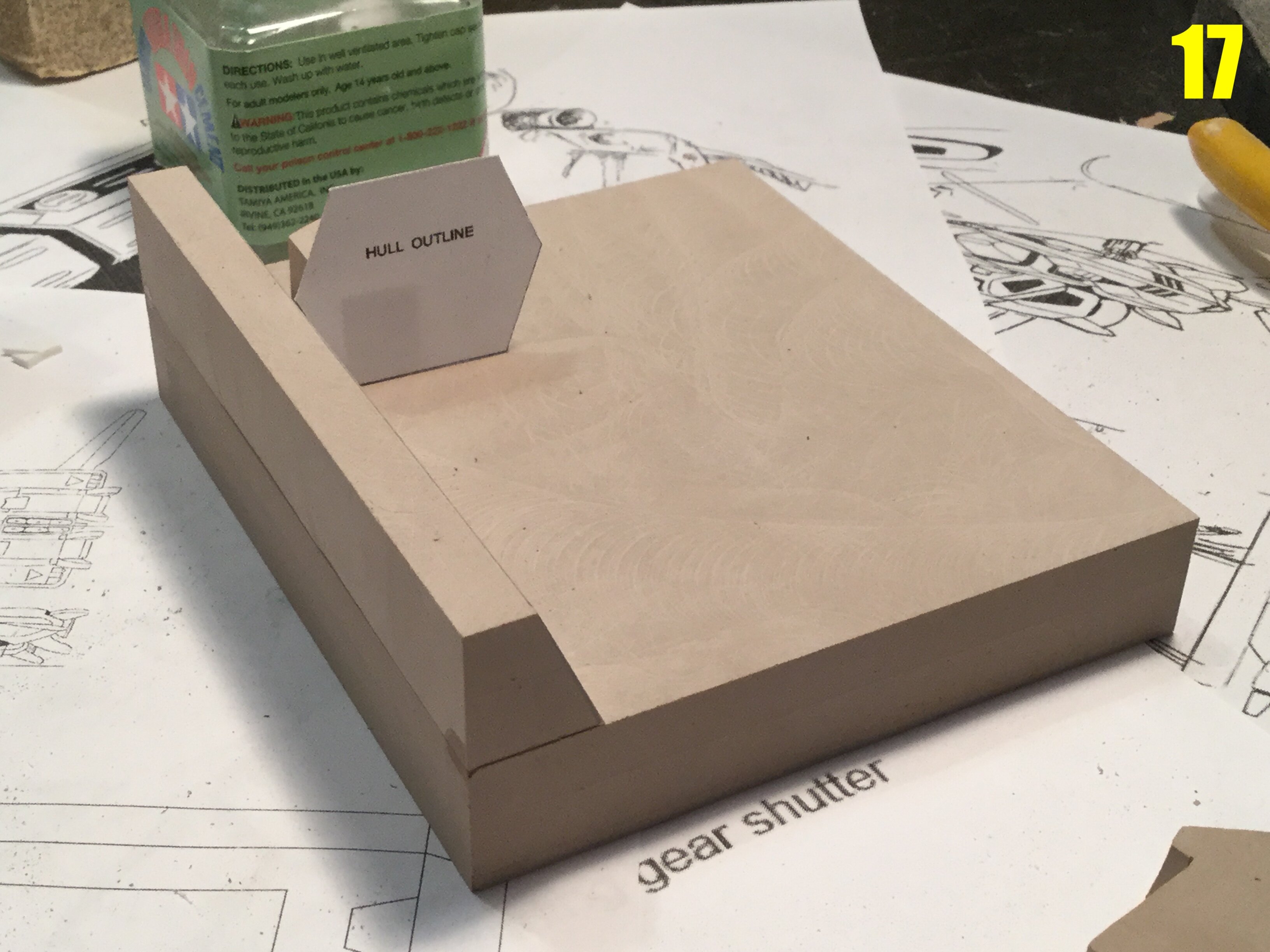
Captain’s log: September 2nd, 2021. Construction continues unabated, and you will see a great leap forward in this installment, as we go from seemingly generic shapes to parts that actually look like a ship that is very Horizontal. Pic 23: last week we saw some blocks with paper templates attached, and now we begin some basic cutting and parts shaping with the band saw to remove the excess. I could have gone straight to the mill, but chopping the excess is faster, and creates a whole bunch of smaller parts that can be useful for smaller parts. The mill would have just turned all that excess material into confetti. Pic 24: now that parts have been crudely trimmed on the saw, I can start milling more precise dimensions. The paper templates act as eyeball guides and are useful so long as there’s enough flat real estate for the template to be stuck to. Pic 25: after a multitude of smaller milling operations on the piece that will be the thruster housing, a very meticulous series of passes are made to hollow the part out. The hull outline was scribed with the jaws of my calipers, and roughly traced over with a pencil for better visibility. Pic 26: these two parts will form the blue-grey aft section of the ship, and will be combined into one part shortly. The shapes were simply too complex to make as one single piece, so it’s quite common for me to break-down certain parts into several sub-assemblies and then combine them into something easier to mold. Pic 27: the same two parts now combined. Now will come the careful filling and sanding of the gaps. Pic 28: the fuselage part just aft of the neck. This is in fact the main hub for the kit, as the neck, aft section, cargo mounts and cargo containers will all attach to it. Here I am doing some parts shaping with a diamond file. Pic 29: the beginnings of the cargo containers. The parts are bonded with plastic cement and placed in the jig to solidify. Pic 29B: the cockpit module still very crude. The main gull was originally much narrower, but as I began sculpting, I noticed that I’d have to widen it for it to look faithful to the line-art, hence the copious amounts of putty. Pics 30-31: after much sanding and test-fitting, the parts are actually starting to look pretty good. While there are still lots of parts to fabricate, at least the main structure looks pleasing. Tune-in for more progress next week!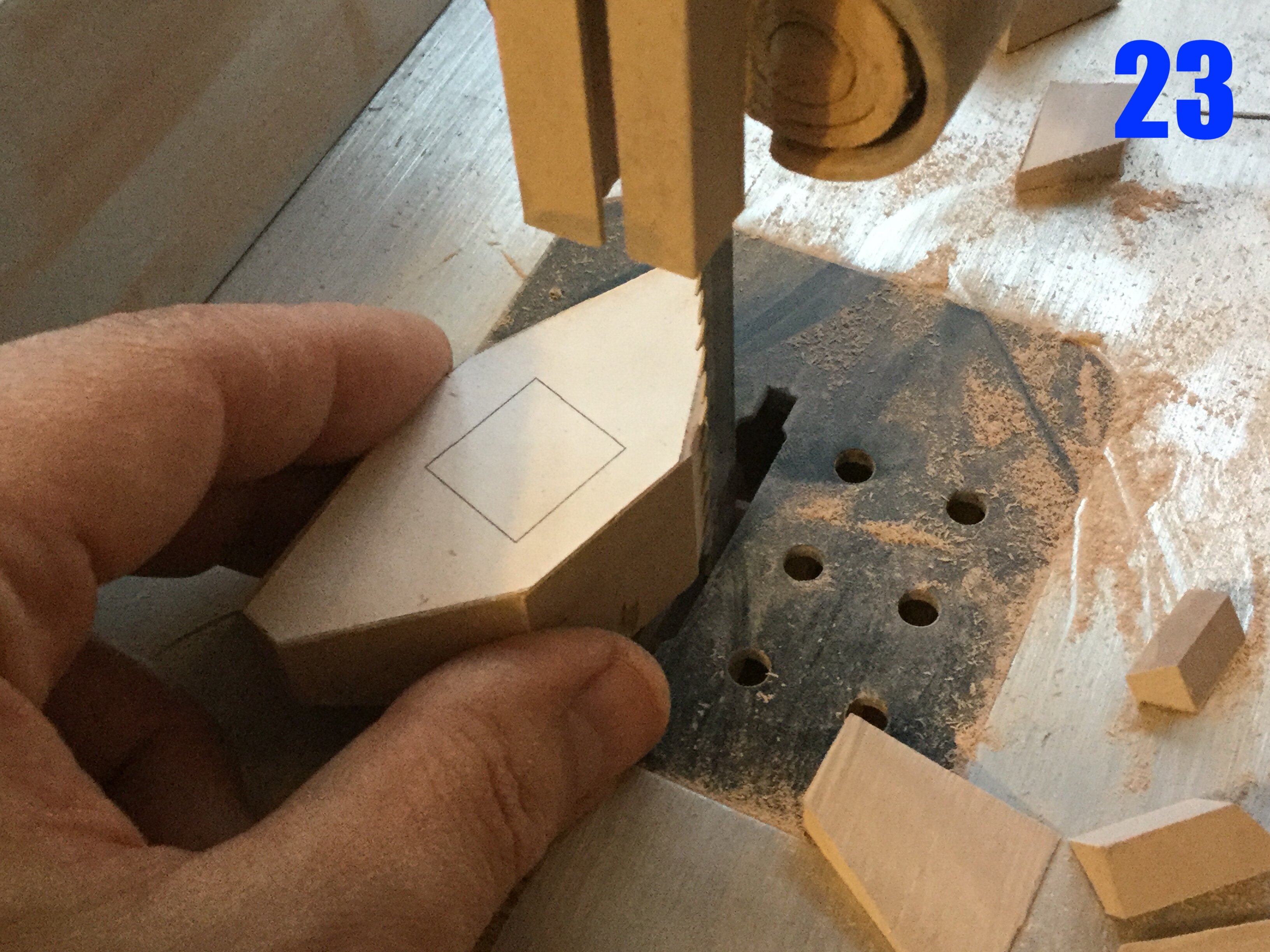
-
The Official Moscato Hobby Models Thread
captain america replied to captain america's topic in Anime or Science Fiction
I would've totally asked to use your pic for the contest poster, but as you'll most likely be participating, I also understand the need to remain impartial. Guys, I have a small favor to ask: can you go troll Brett on the Return2KitForm Facebook page and ask him to be a judge for the contest? It would really mean a lot. -
The Official Moscato Hobby Models Thread
captain america replied to captain america's topic in Anime or Science Fiction

-
MOSPEADA HORIZONT in 1/350?
captain america replied to captain america's topic in Anime or Science Fiction
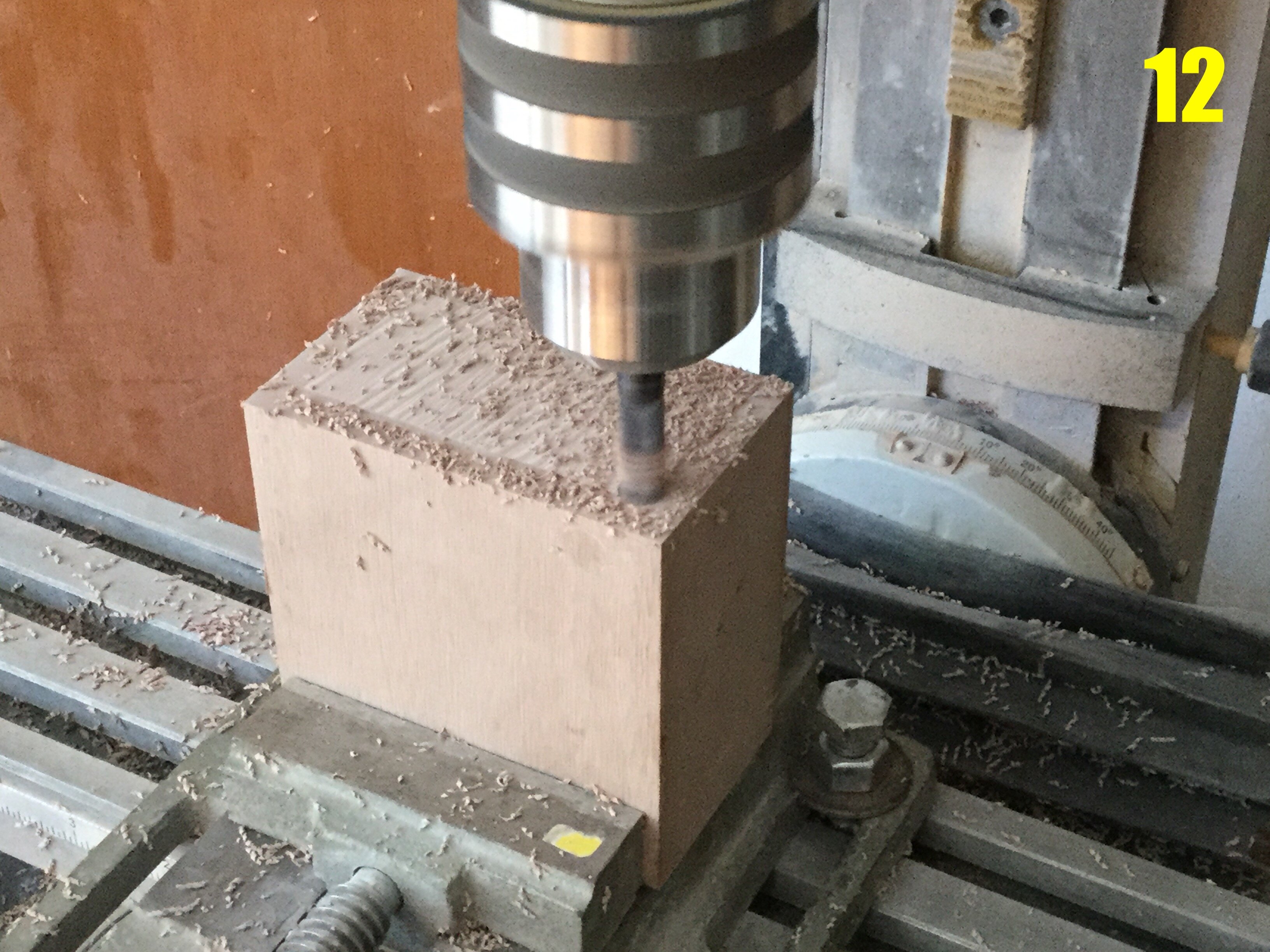
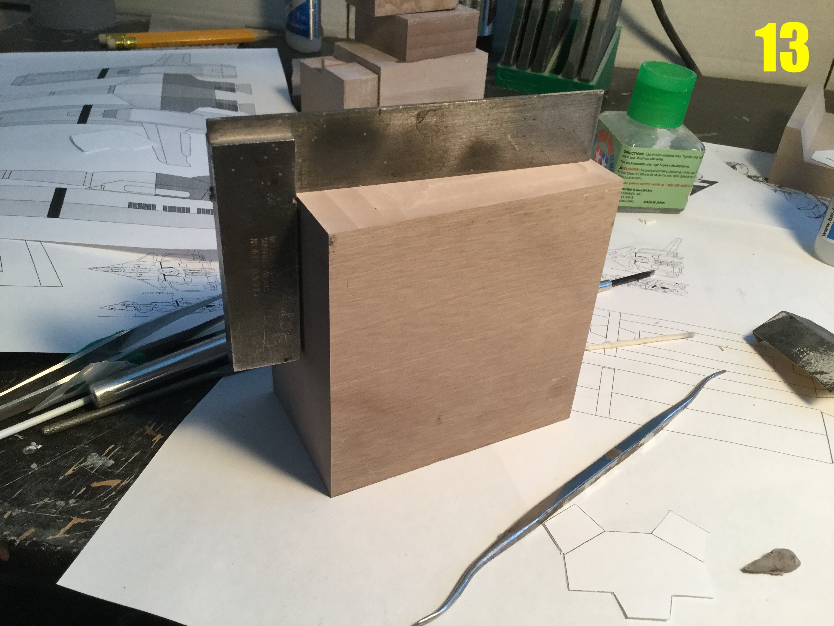
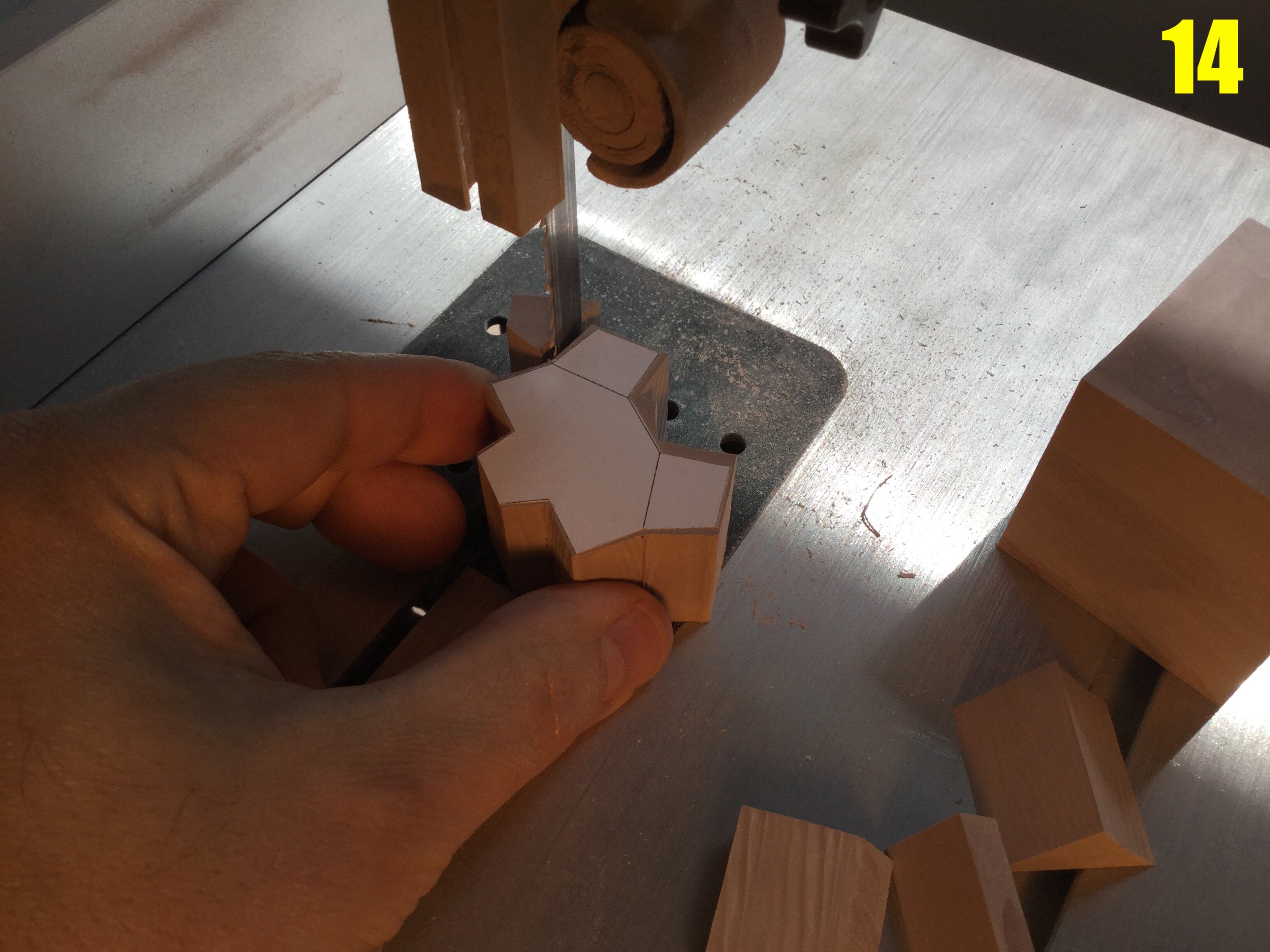
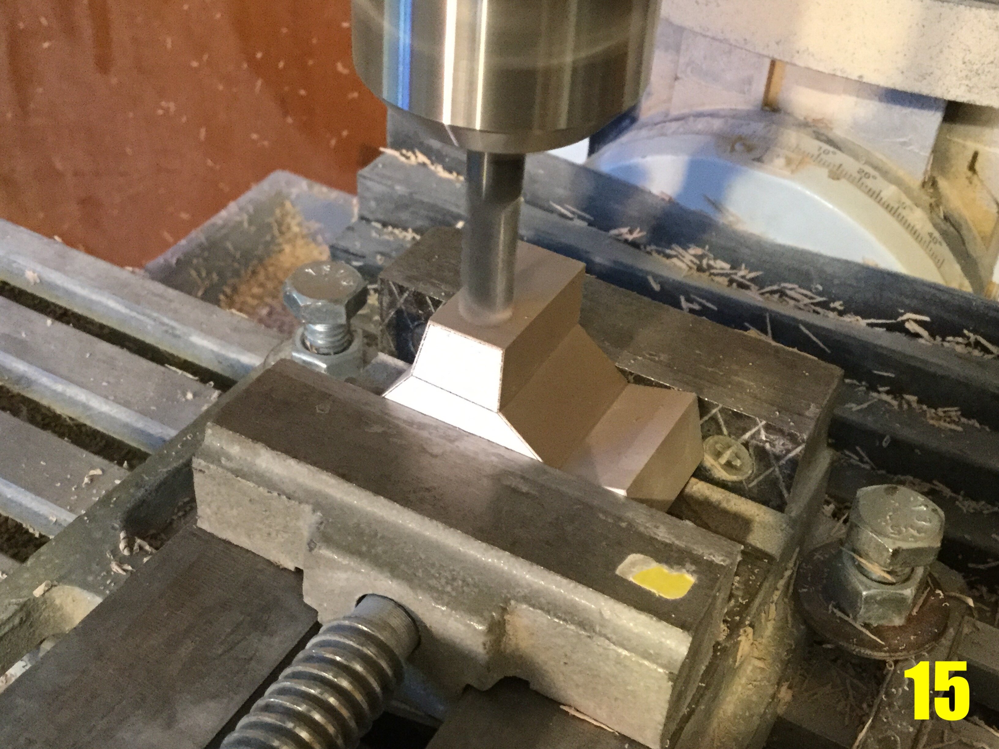
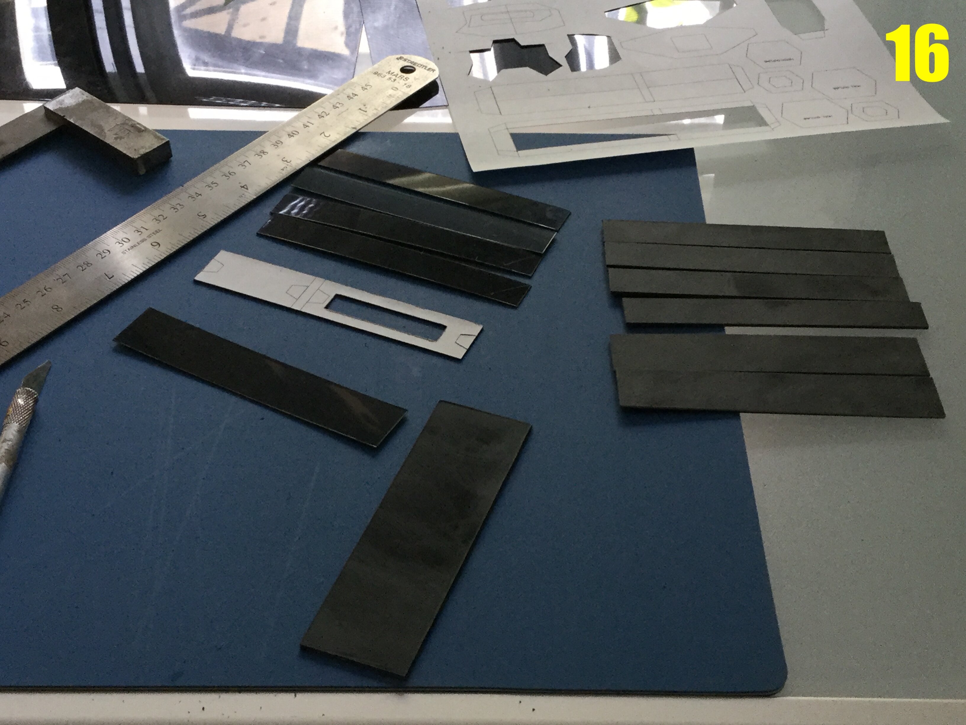
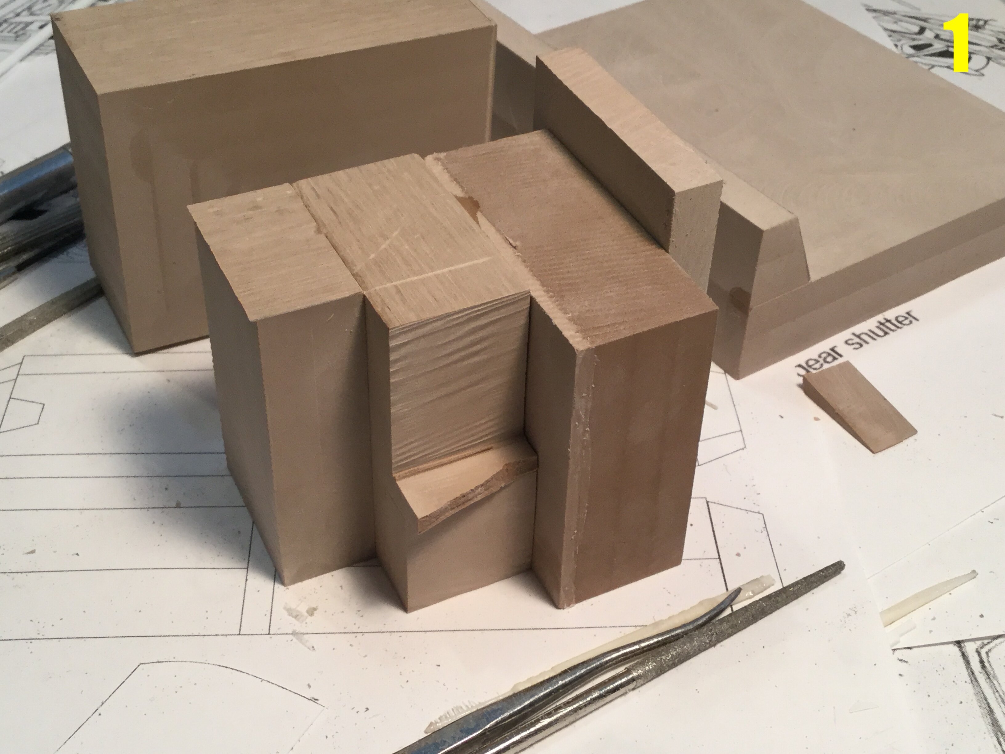
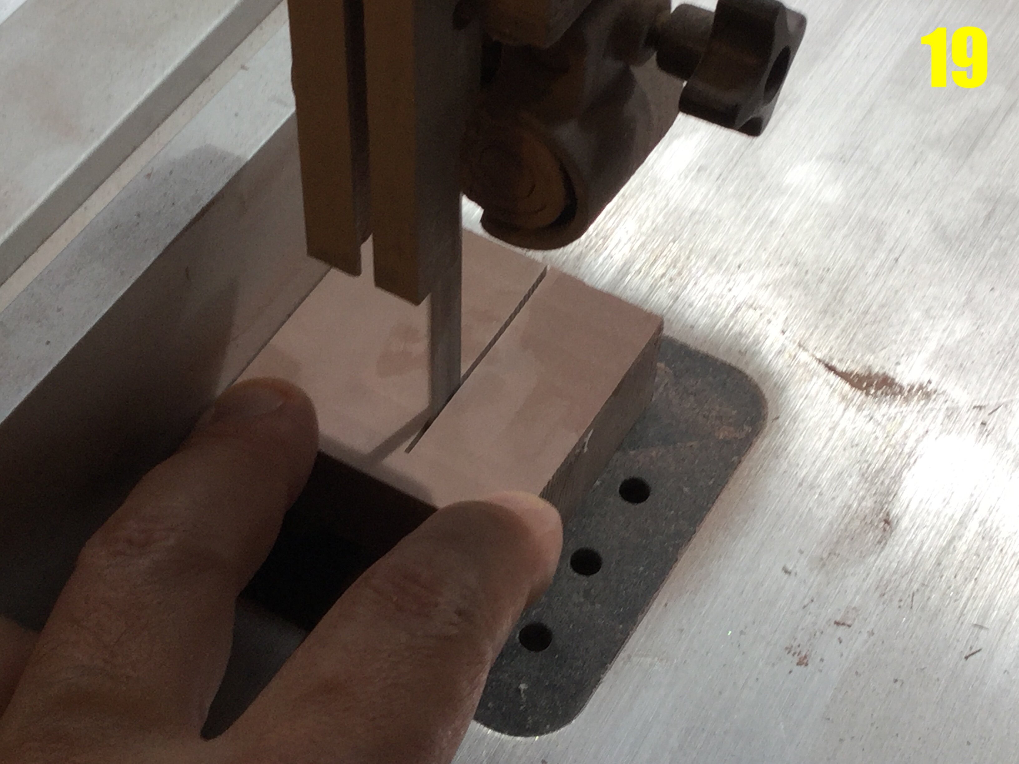
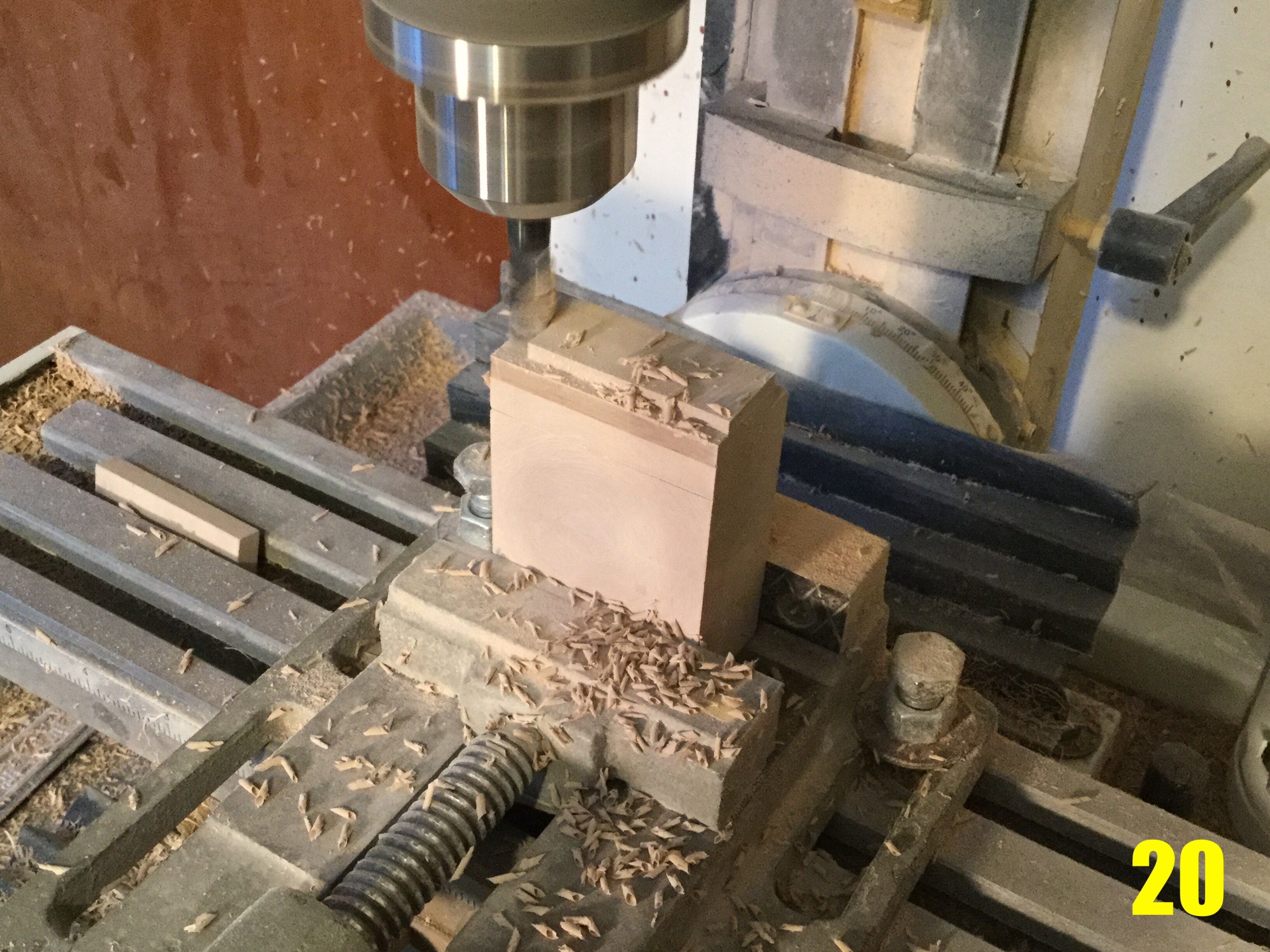
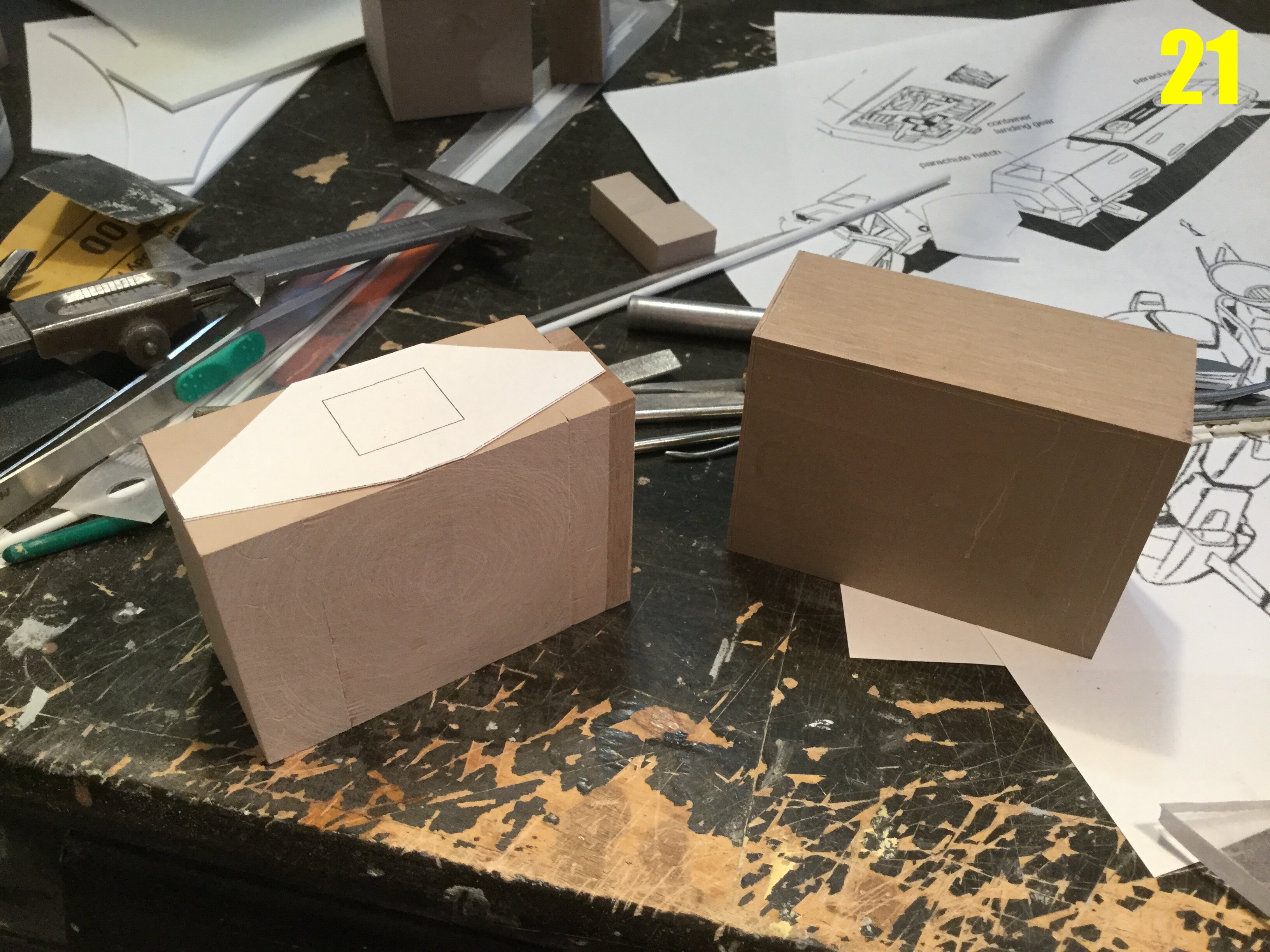
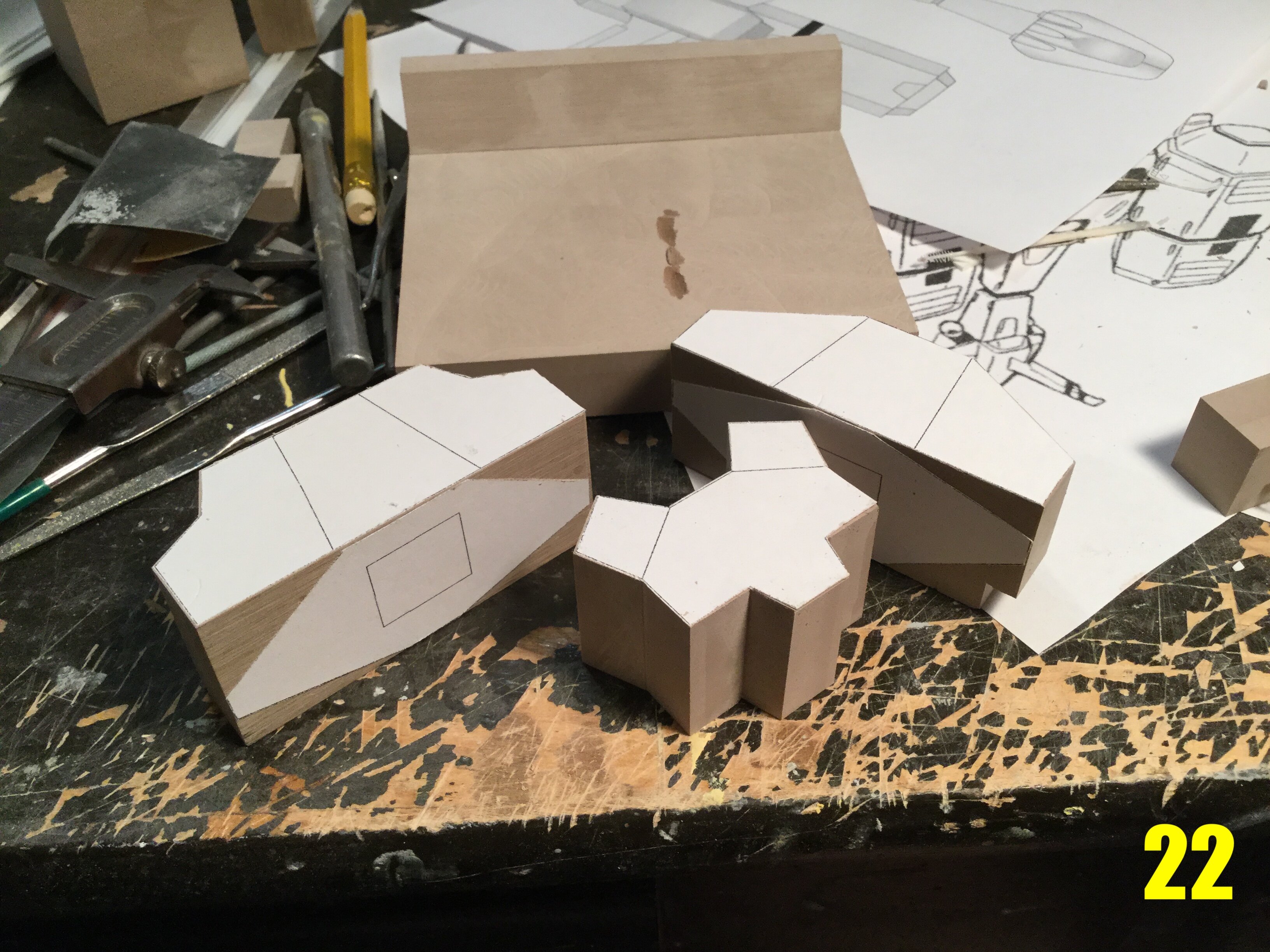
Captain’s log: Thursday, August 26th. Now that the fighter/booster is done, I can concentrate on the main ship. Since the various views of the ship don’t match-up, I opted to take the prettiest view and extrapolate the blueprints from that. Pic 11 shows the almost complete diagrams. Pic 12: in anticipation of the build, I start by milling some blocks of modelling board to create perfectly square blocks which will be needed to create precise shapes. Pic 13: the scrap block from pic 12, now perfectly squared and ready! Pic 14: with paper templates now affixed to a variety of blocks, I can begin the initial construction by removing some of the excess material with the band saw. Pic 15: the same part is now placed into my milling vise and more precise shaping is achieved with the mill. As with all parts, there will be a variety of operations needed to obtain the proper dimensions, with much backing-and-forthing. Pic 16: I needed a change of scenery, so I put aside the modelling board and began cutting the initial components for the cargo containers. These will be made mostly from styrene sheets of various thickness. While seemingly simple in design, they actually have many awkward details. As such, they will be very tedious and time-consuming to build, so I might as well start on them sooner rather than later. Pic 17: because of their hollow nature and hexagonal cross-section, I decided to make a crude jig for assembling all the hull components. This will ensure that the containers look precisely engineered, and not the result of some fly-by-night ham-fisted model-maker. Pic 18: I had a few smaller blocks which I decided to merge into a larger block to minimize waste. The beauty of this material is that it can be bonded very quickly and safely with CA glue, and then machined as if it were a single piece. Pic 19:… But before I do that, I decide to do some minor trimming with the band saw. Those smaller scrap pieces will be useful later on. Pic 20: a little extra machining before I bond all the scraps together. Pic 21: the block on the left was made from the scraps you saw in pic 18. You can still see a few seams here and there, but those will disappear as I begin to shape and refine the block. Pic 22: some of the major hull components in crude form, awaiting further refinement. While the initial build photos probably aren’t very exciting, these steps are the foundation of any project, and lay-out some of the most critical steps in the evolution of a project. The time and effort spent carefully calculating, measuring and cutting will yield far more precise shapes than could ever be made by simply hand carving, so it’s time well spent. You probably can’t tell, but at this rate, I will already have most of the structural parts fleshed-out by next week. Stay tuned!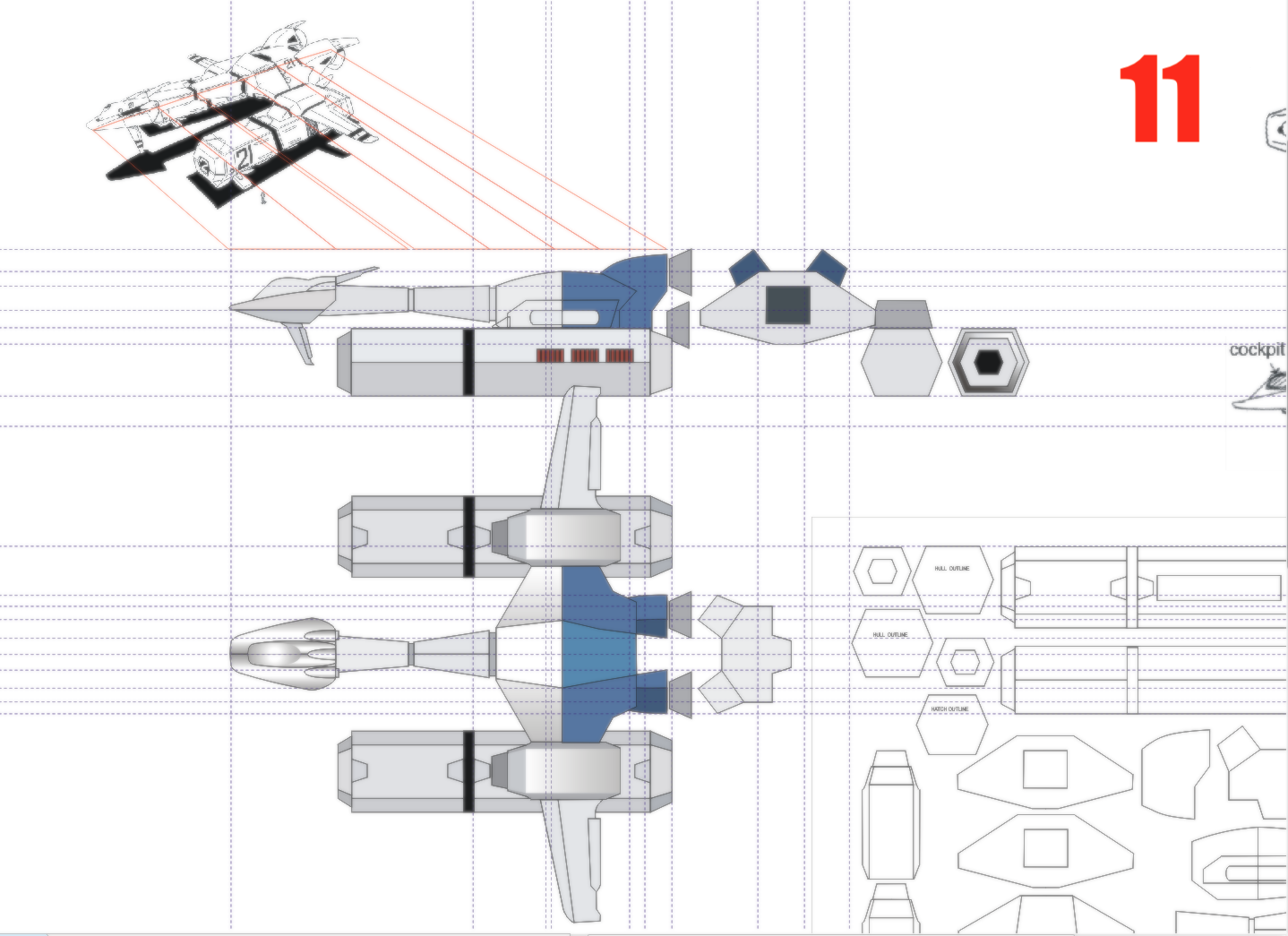
-
1/48 SOUTHERN CROSS BIOROID
captain america replied to captain america's topic in Anime or Science Fiction
That was/is one of the bigger issues with the design (one of many): it makes no functional sense, and posed a challenge to the overall mobility of the model. The old 1/48 plastic model is itself a testament to this fact. I suppose that a modeler could add a thin piece of black nylon stocking to the underside of the rib parts to reproduce the black area shown in the line-art,but I tend to think it looks better (and more alien) open. -
MOSPEADA HORIZONT in 1/350?
captain america replied to captain america's topic in Anime or Science Fiction
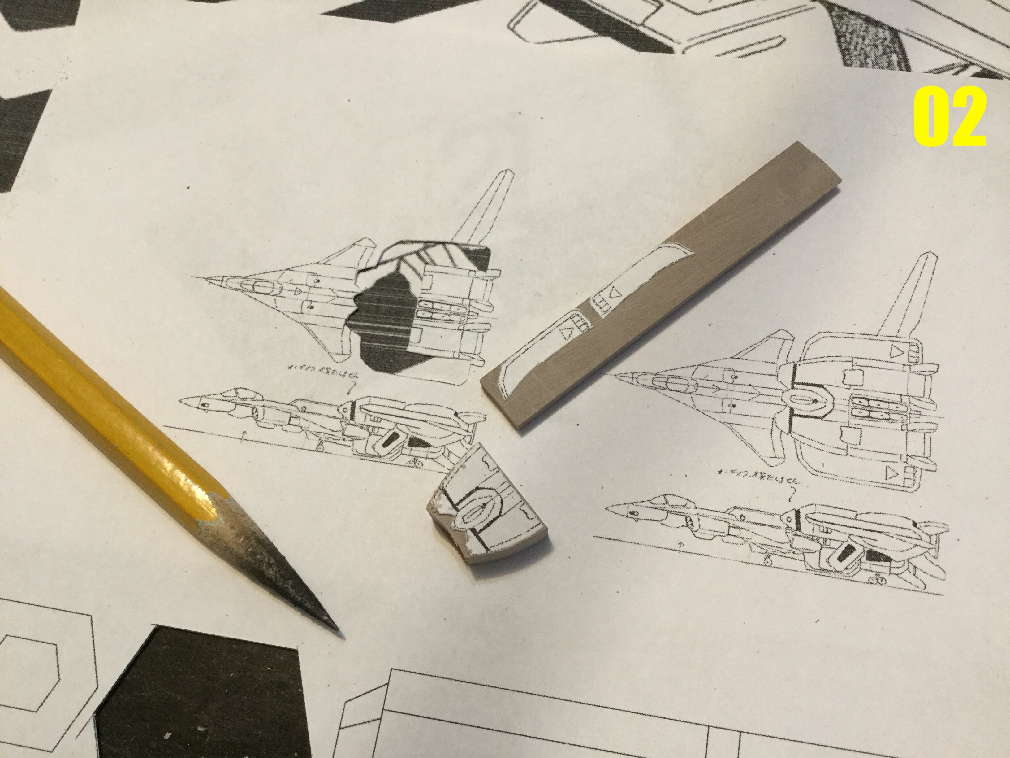
The plan and side diagrams of the Legioss/Tread in image 02 are reference drawings that the animators used: everything that was drawn for the anime/publicity art was based on that standard. Even the toys and resin models reproduce that gap, so I'm not quite sure what you're referring to. -
MOSPEADA HORIZONT in 1/350?
captain america replied to captain america's topic in Anime or Science Fiction
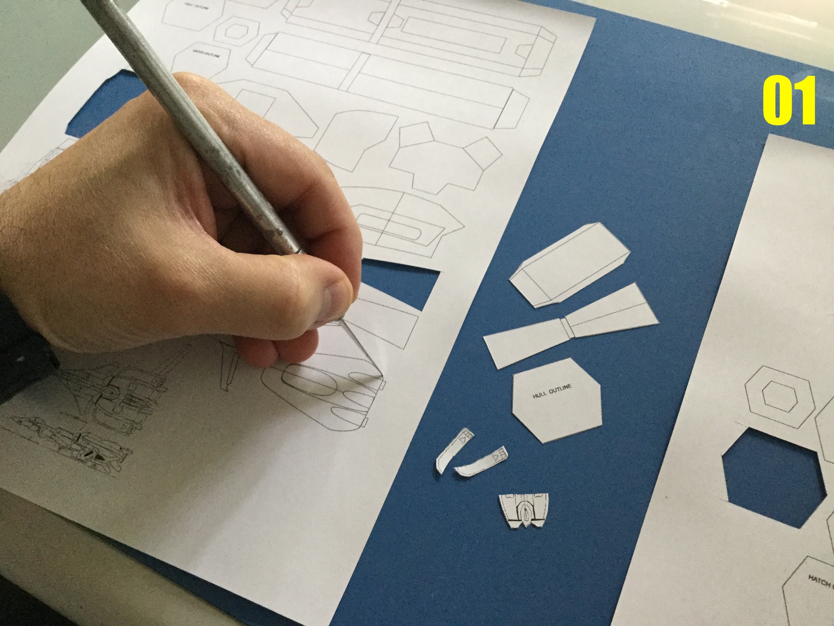
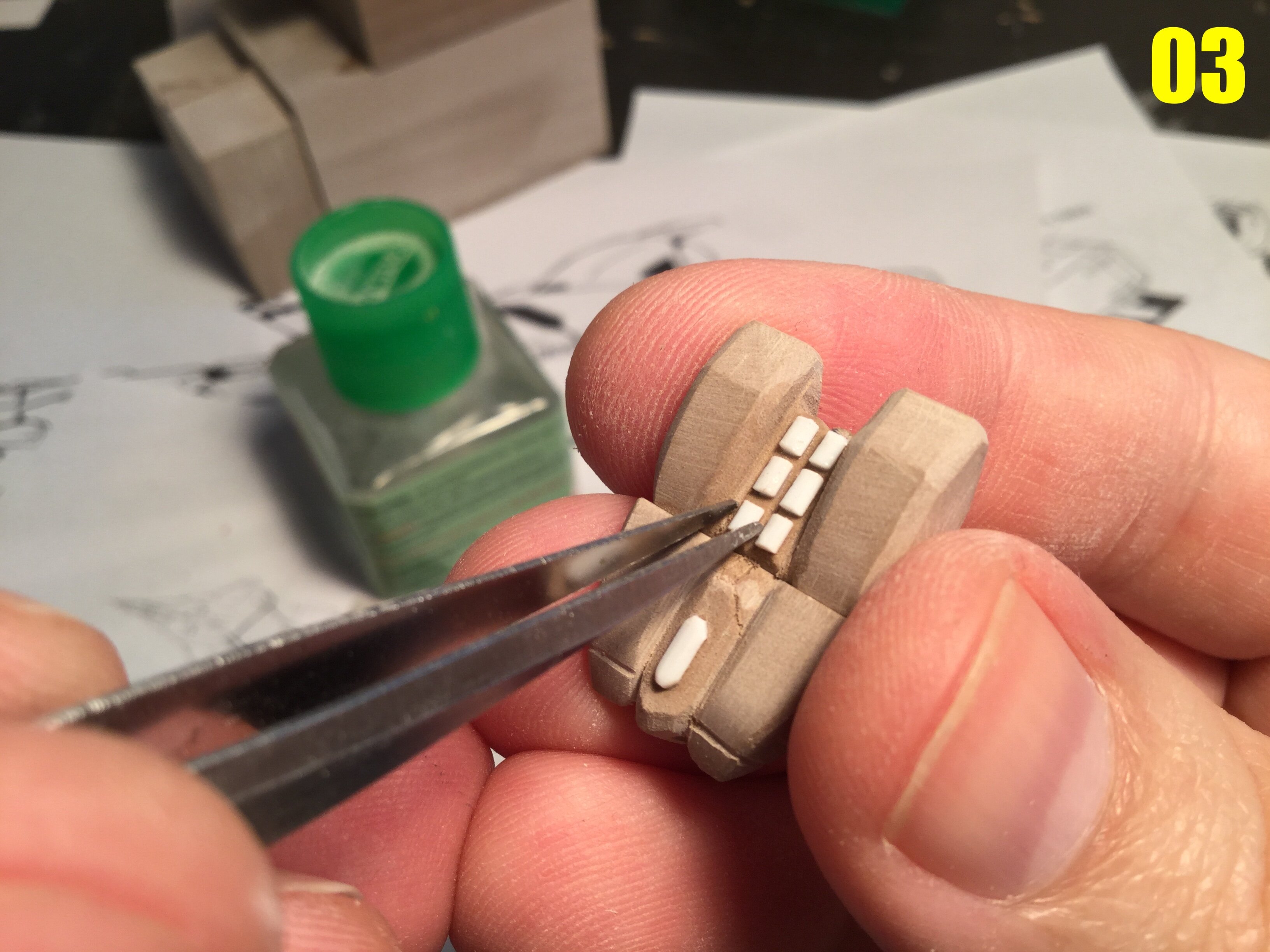
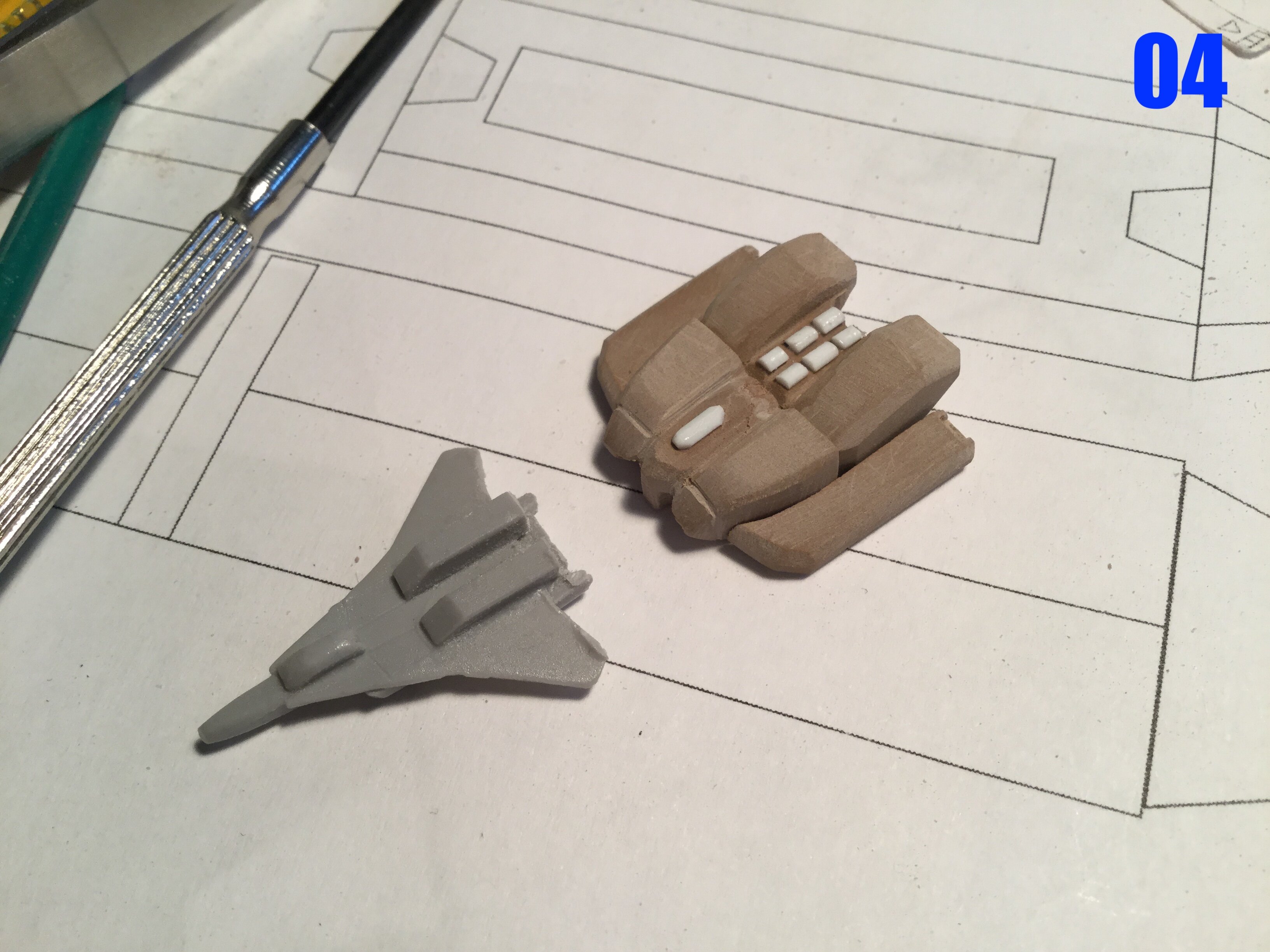
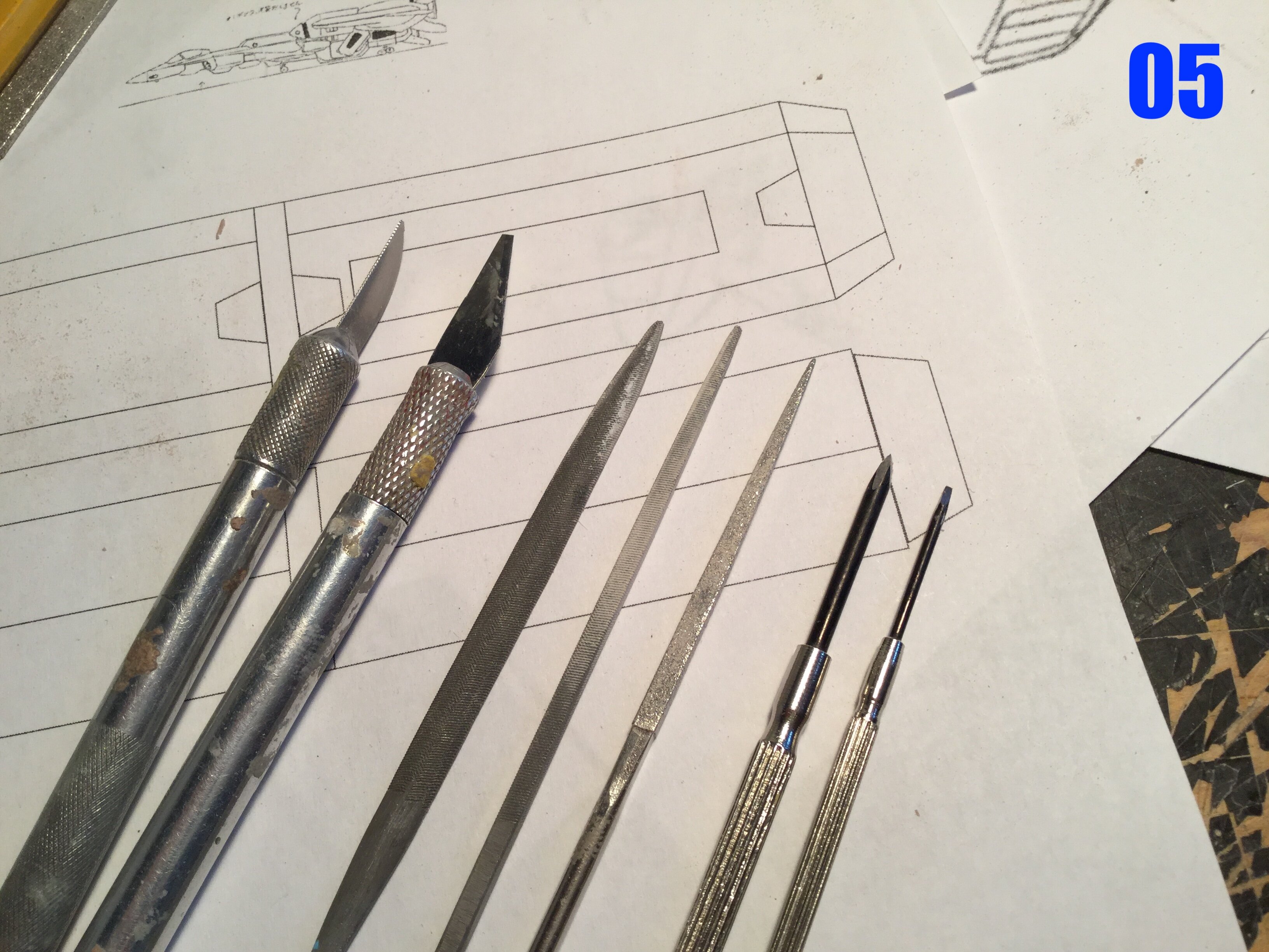
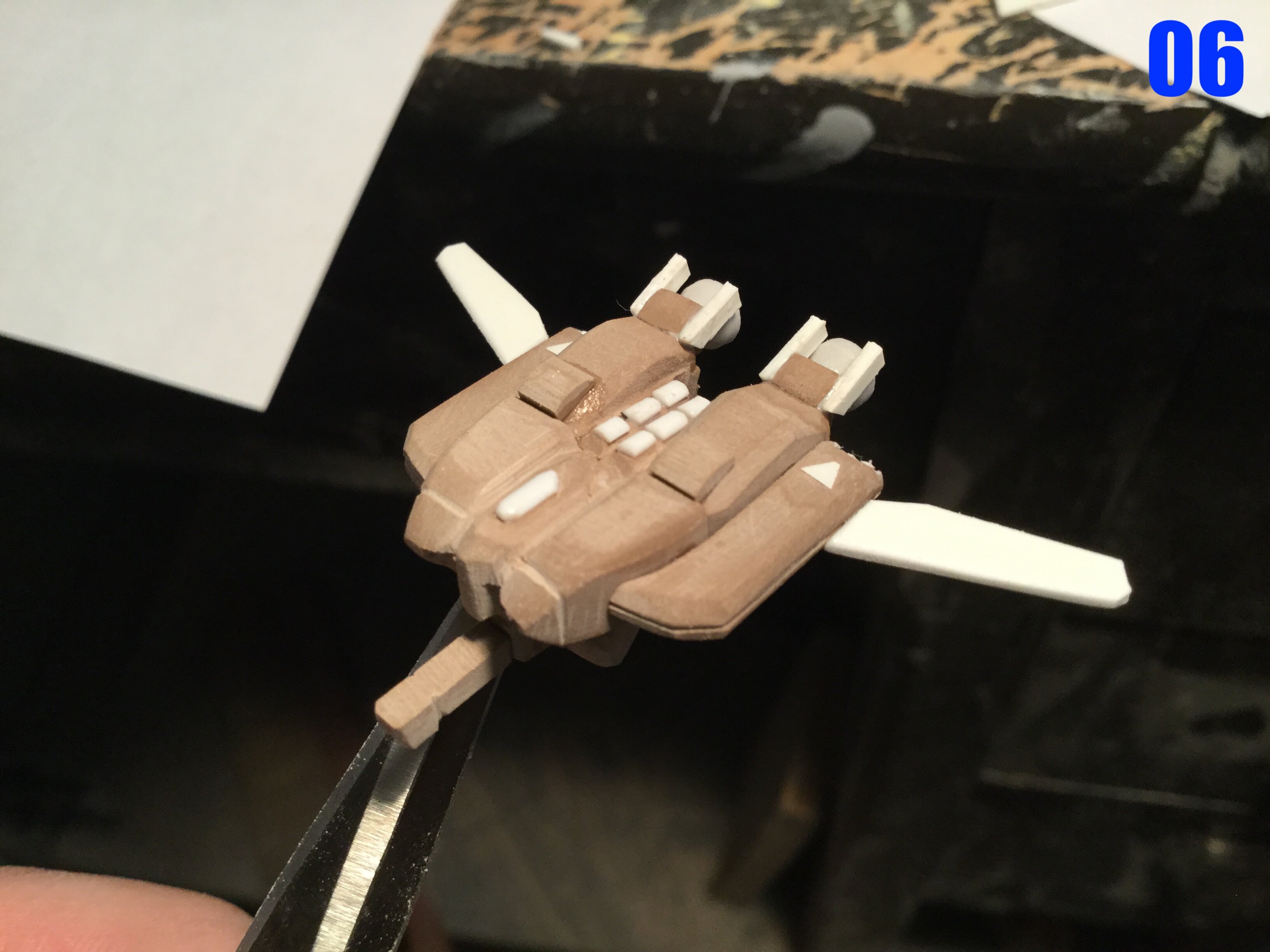
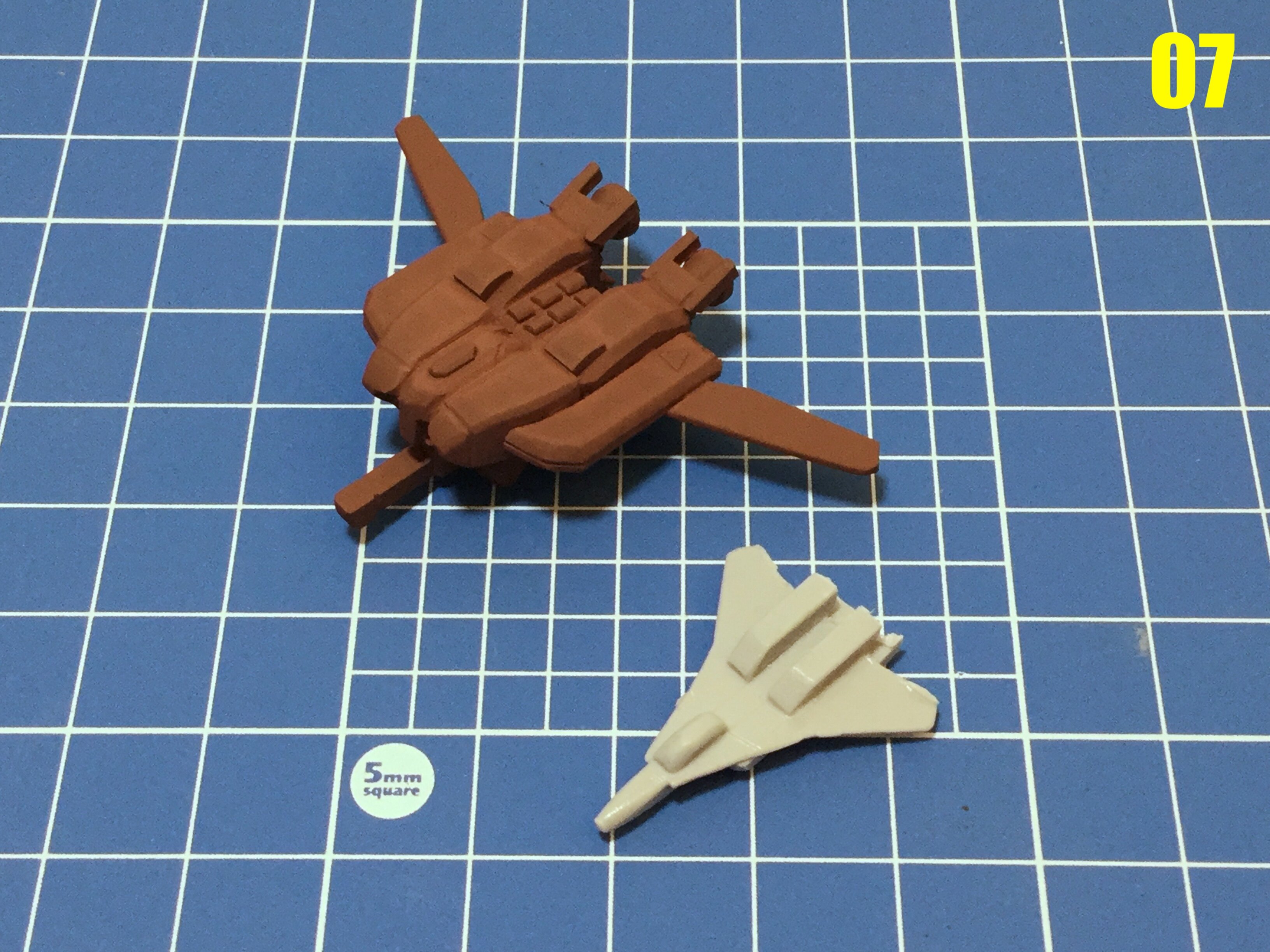
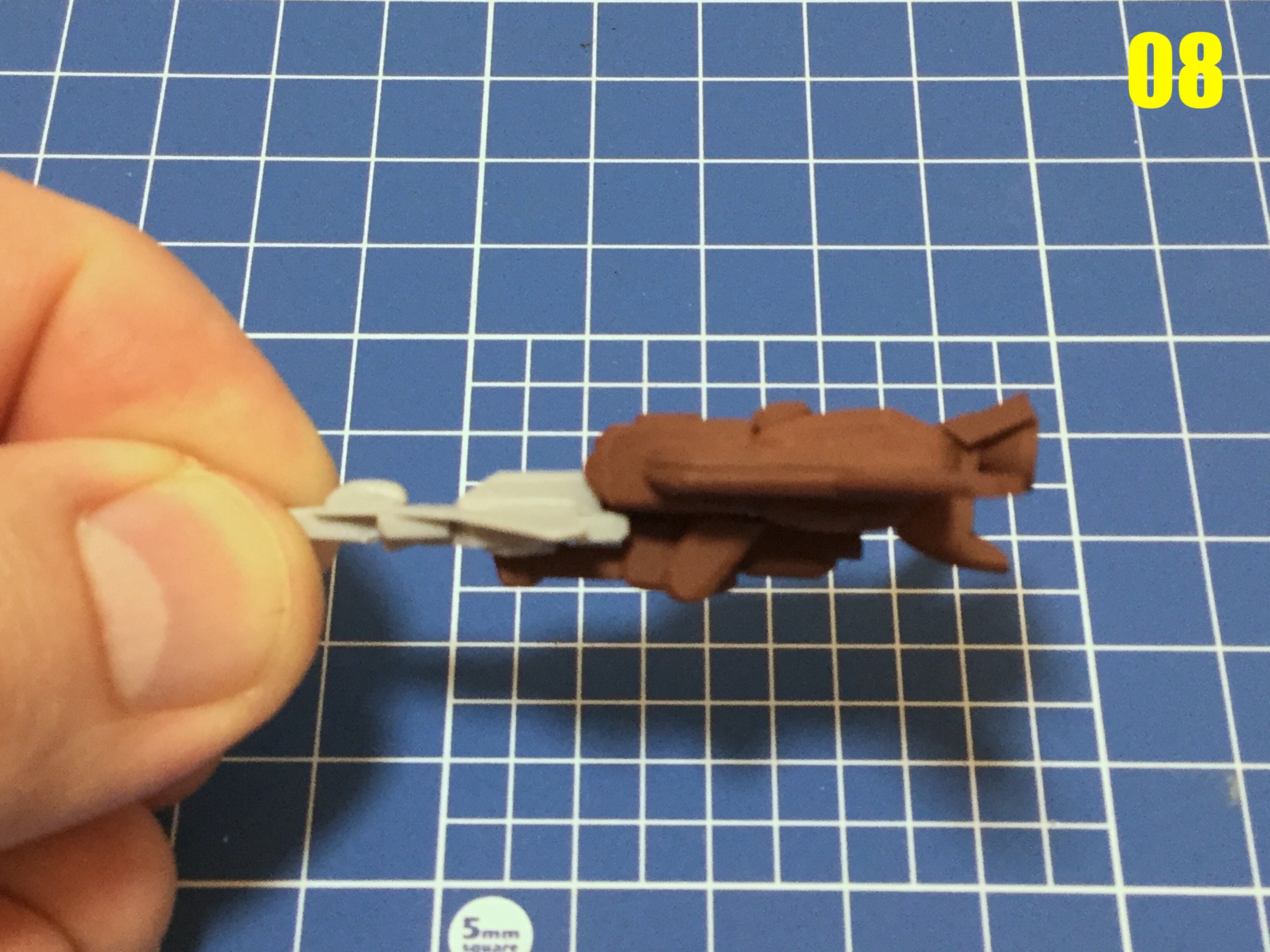
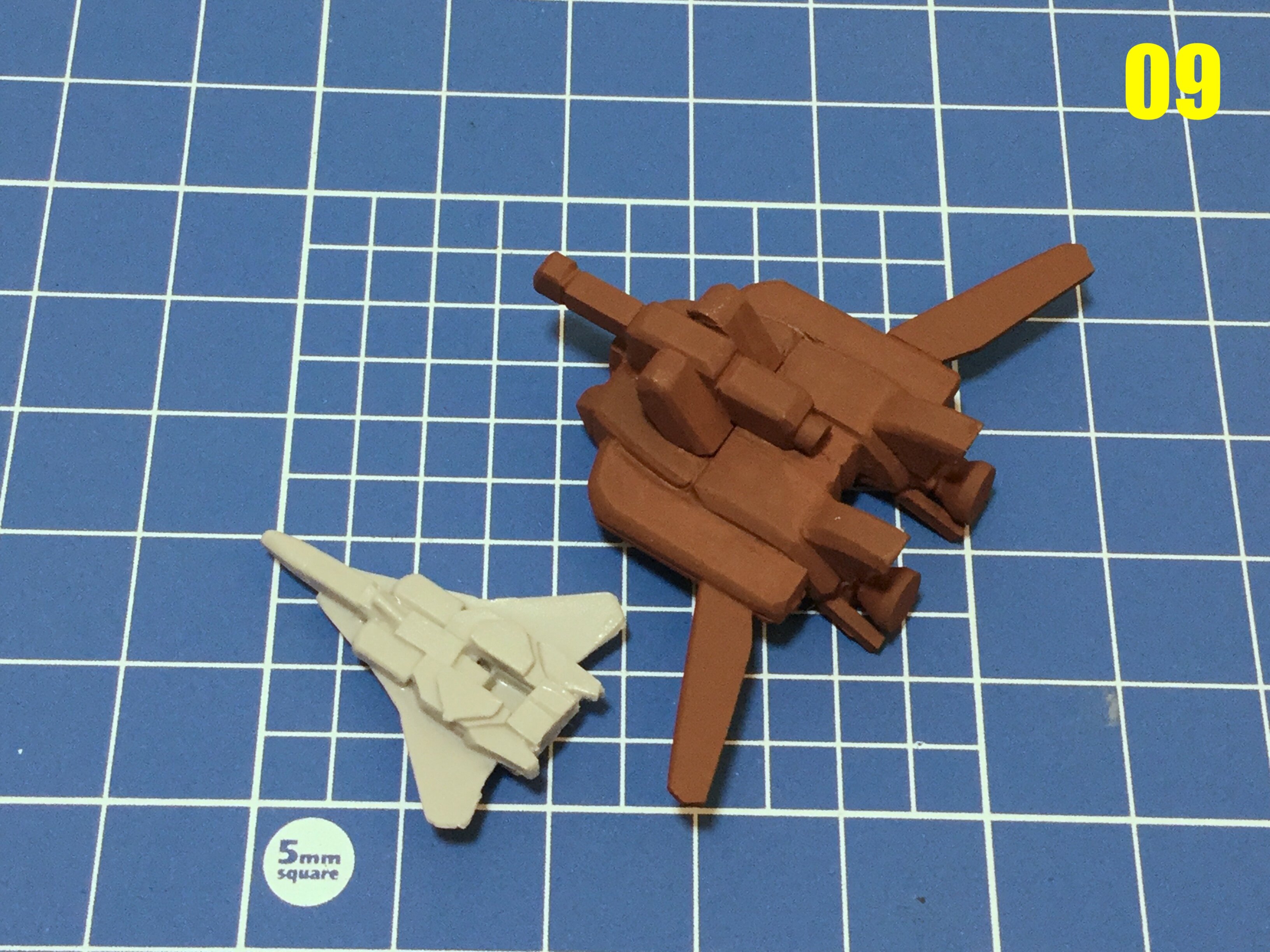
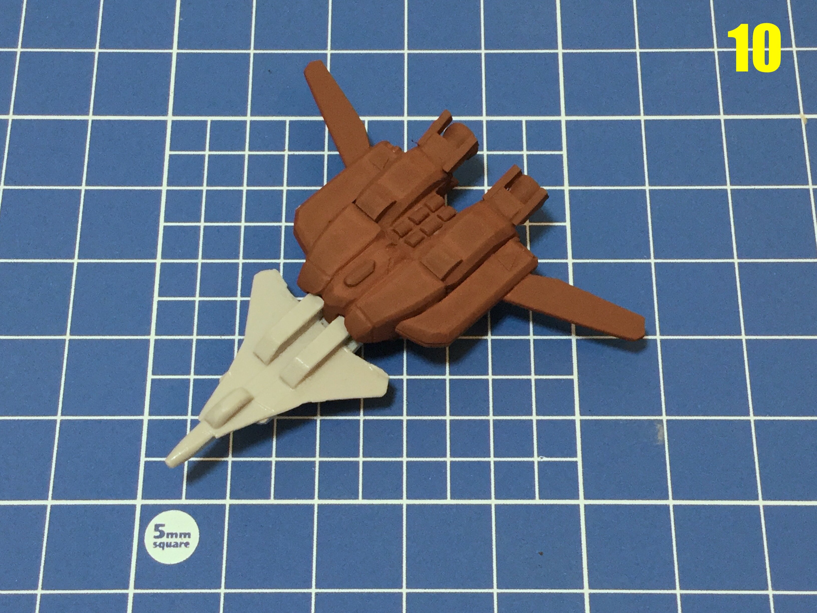
Captain’s log: August 19th, 2021 And so it begins! As per my usual procedure, I’ve collected as much visual reference as I could on the ship itself, scrounged-up a few blocks of modelling board, and some styrene sheet, which will be needed for the cargo container hulls. Upon scrutinizing the Anime style sheets, I was (not) shocked to learn that, just like everything else from the series and this era, the drawings don’t correspond to each other. Fair enough, I decided to back-engineer the most prominent beauty-shot and make usable diagrams from that. I printed those out, as well as scale diagrams for the fighter/bomber, and since that’s probably the most challenging part of the build, I decided to start there. Pic 01: since I’ve got the diagrams printed, I might as well start cutting some of them out. This is warm-up for the uber-tiny Tread diagrams. Pic 02: my poor eyeballs! The parts are so small that I can barely machine them, and will need to resort to some old-school hand sculpting to get this little guy looking right. Pic 03: after a bit of hand carving, those fiddly little bits are starting to look like something. Smaller details are made with styrene, and bonded to the modelling board with regular old Tamiya cement. Pic 04: not looking too shabby. I’m using one of the castings for the fighter I included with the Starfish (Garfish) to adjust the fit of the Tread. The fighter itself is absurdly tiny at 1/350, and the (Tread) booster isn’t much bigger. Pic 05: some of the tools I used to carve the Tread mini-me. From left to right: dine razor saw, hobby knife, steel files (for finer finishing), diamond files for shaping, and home-made chisels made from old flat-blade screwdrivers. Pic 06: it’s kinda starting to look right at this point. A little more refinement is needed, then I can prime it. Pic 07: the finished part, now primed and awaiting a little wet-sanding. No, it doesn’t transform!! Pics 08-10: the two units can be built combined or left separate, so you have even more display options. Now that this little falla is done, he’ll be put aside so that I can turn my focus to the mothership. Tune-in next week to see more!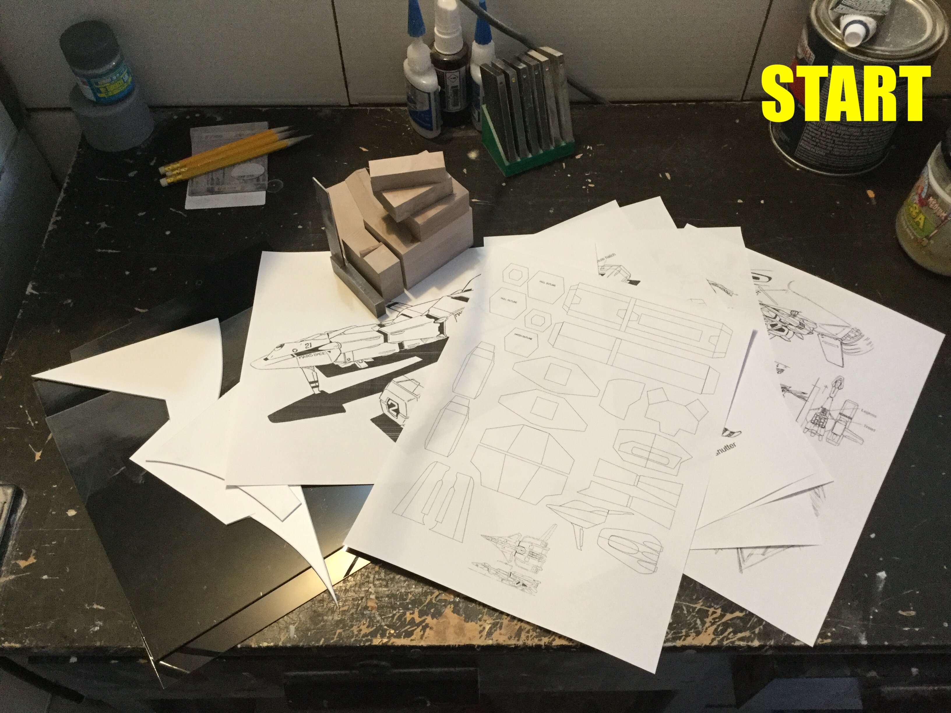
-
MOSPEADA HORIZONT in 1/350?
captain america replied to captain america's topic in Anime or Science Fiction
First build update coming tonight! -
MOSPEADA HORIZONT in 1/350?
captain america replied to captain america's topic in Anime or Science Fiction
2 pre-order slots left. -
The Official Moscato Hobby Models Thread
captain america replied to captain america's topic in Anime or Science Fiction
Let me concentrate on the Horizont for now. When that's done, we can revisit it. -
The Official Moscato Hobby Models Thread
captain america replied to captain america's topic in Anime or Science Fiction
I'd tackle it. I think over the years I've proven my competence in translating line-art into three dimensions. Can't be worse than the old B-Club sculpt, which looks like a Happy Meal toy. The critical factor is demand... And available reference material. In that order. -
1/48 SOUTHERN CROSS BIOROID
captain america replied to captain america's topic in Anime or Science Fiction
It's possible. My concern is that offering a Biopsycher and Spartas in the same year would be too much of a financial burden within the same series for most people, so if I elect to do one subject next year, the other would have to wait until the following year. I also have a potentially interesting Mospeada subject in mind that I think would be well received. -
The Official Moscato Hobby Models Thread
captain america replied to captain america's topic in Anime or Science Fiction
That echoes my thoughts on the subject. The sketchy, imprecise rendering and the lack of alternate views means I'd have to spend lots of time engineering something physical that I suspect too few people would be ready to pay for. -
MOSPEADA HORIZONT in 1/350?
captain america replied to captain america's topic in Anime or Science Fiction
-The fighters will be separate from the bosters. Aircraft mode only, as the booster is so small at 1/350 that it's barely larger than a quarter (wings excluded). -Yes, the Horizontal Ship will have attachment points and the drop-down box for the fighter cockpit as a display option. -
MOSPEADA HORIZONT in 1/350?
captain america replied to captain america's topic in Anime or Science Fiction
Oe Horizontal Ship kit includes one fighter/booster. The addition of the fighter/booster combo (3 Legioss, 3 Tread) brings the total to $206, as detailed in the first post. -
MOSPEADA HORIZONT in 1/350?
captain america replied to captain america's topic in Anime or Science Fiction
Yes it is, because only the first 30 orders will be able to get escort sets. From order 31 onward, they will no longer be available. -
MOSPEADA HORIZONT in 1/350?
captain america replied to captain america's topic in Anime or Science Fiction
Everyone knows the shelf eventually wins! Y'all can start sending your payments in now. Ready, set... GO! -
1/48 SOUTHERN CROSS BIOROID
captain america replied to captain america's topic in Anime or Science Fiction
Those builds make my heart go pitty-pat! ... Oh, and I fixed your pic.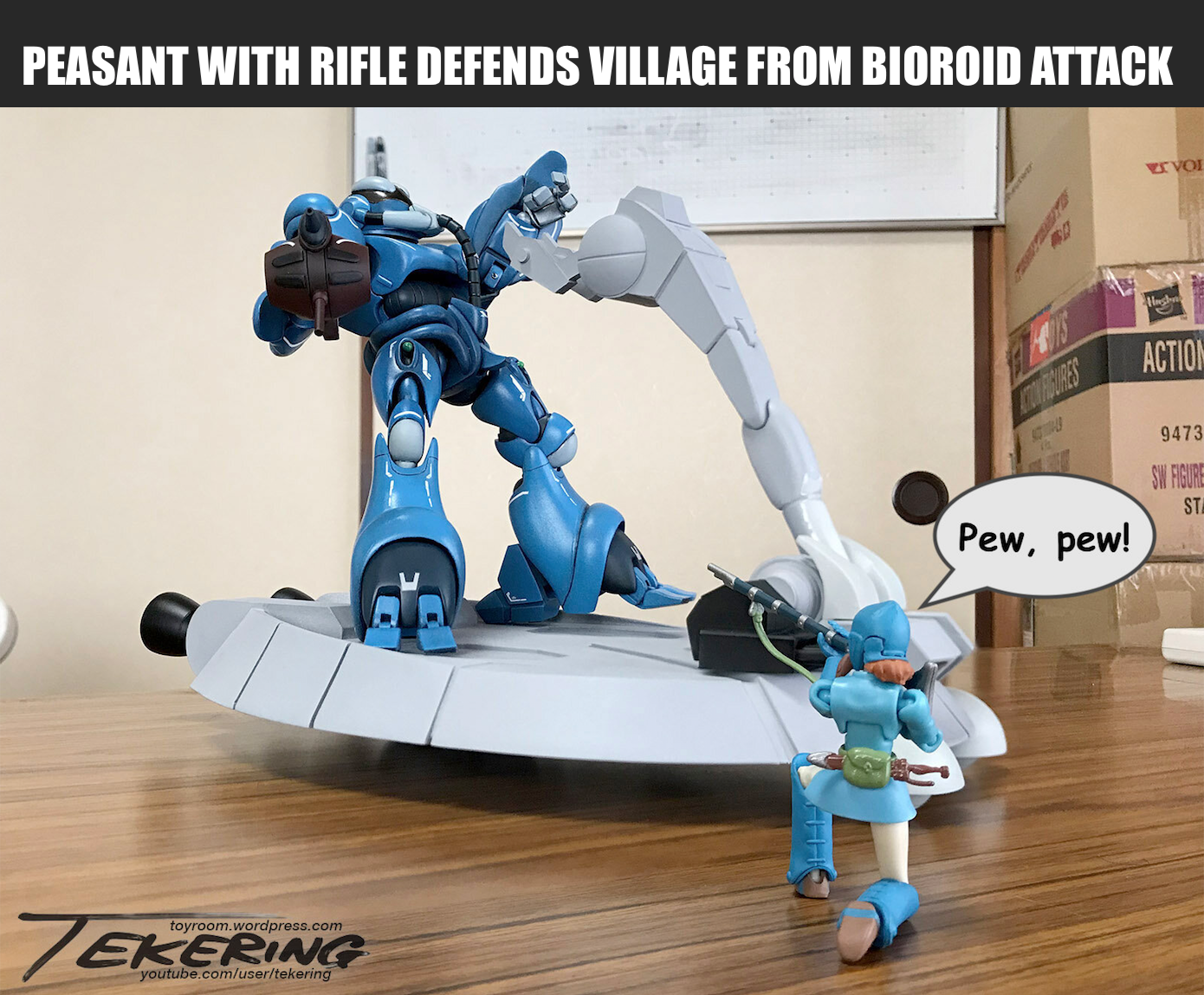
-
1/48 SOUTHERN CROSS BIOROID
captain america replied to captain america's topic in Anime or Science Fiction
I'm just giddy looking at all these progress pics! In fact, you've inspired me to bring some of those much-needed corrections to the Biover platform, so when I get around to offering the Hemorroid (Biopsycher) kit next year, the sled will have the updates. So now with all you guys building like crazy, I have to get serious about this modeling competition I'm setting up for September. In the meantime, please accept my humble meme.
-
MOSPEADA HORIZONT in 1/350?
captain america replied to captain america's topic in Anime or Science Fiction
You Need A Fleet Of Ships!!! -
MOSPEADA HORIZONT in 1/350?
captain america replied to captain america's topic in Anime or Science Fiction
Hi guys. I'm officially opening up the payments for the kits today. All payments by Paypal and Bitcoin are welcome, as usual. You can use the price list in the first post to determine the amount to send, just be sure to include a breakdown of your order along with your payment so that I know what to process! If paying with BTC, just send me a PM when you're ready to send payment and I'll do the currency conversion on the spot, because it fluctuates quite a bit. Example: -2 Horizontal ships: $325 -1 fighter/booster combo (3 fighters, 3 boosters): $20 -Total: $345 CAD For international customers, you may place your orders with Return 2 Kit Form as usual I've already started drafting technical drawings for the ship. Shocking thought it may seem, none of the reference art ligns-up properly!! So back to my tried-and-true method of starting with the most prominent line-art and back-engineering it. I'll start the actual building process once the first 30 orders are placed. Aaaand... Go!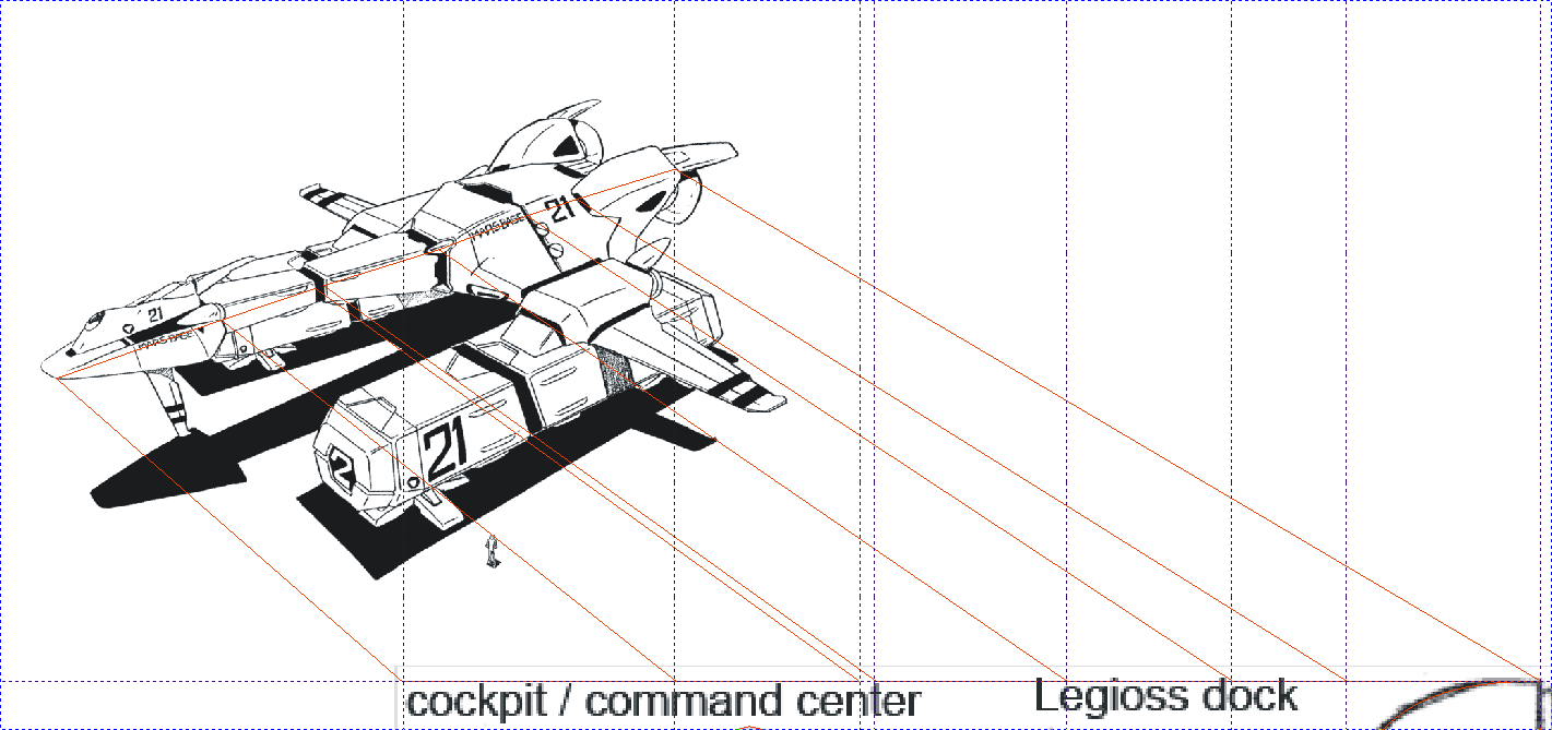
-
MOSPEADA HORIZONT in 1/350?
captain america replied to captain america's topic in Anime or Science Fiction
This might be a better place for that question https://www.macrossworld.com/mwf/topic/45610-the-official-moscato-hobby-models-thread/page/7/ -
1/48 SOUTHERN CROSS BIOROID
captain america replied to captain america's topic in Anime or Science Fiction
Hey Ted, Excellent work on the kits, by the way! FWIW, there were a lot of design elements with the design that had me scratching my head, like that wider gap/partition on either side of the front of the sled. I figured it may have been an animation error (one of many) so I just made them all consistent. The yoke guards I can alter without too much trouble, that's my bad. Sled blasters: once again, I think this is just due to horrible animation (and design) inconsistency. You'll notice that the animation also shows the control column in a very reclined position, but for that, the whole sled would have to be *pauses* significantly larger than it already is, to say nothing of the size of the control column itself. If I take one of the screen caps you posted above, and compare it to one I took during the build, you can see a huge discrepancy in the size of the sled, as well as how the sled parts/details are deformed from one view to the next. As such, the rendering of some details I just chalk-up to personal preference.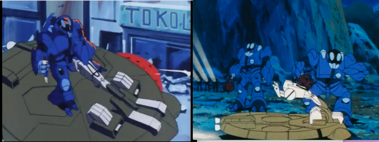
-
MOSPEADA HORIZONT in 1/350?
captain america replied to captain america's topic in Anime or Science Fiction
I think we're a go on this baby. Will start taking payments next week; will have already done most of the technical drawings by then.
