Jaustin89
-
Posts
170 -
Joined
-
Last visited
Content Type
Profiles
Forums
Events
Gallery
Everything posted by Jaustin89
-
Symmetrical Gundam 00 Quan[T] Metal Build Mod
Jaustin89 replied to Jaustin89's topic in The Workshop!
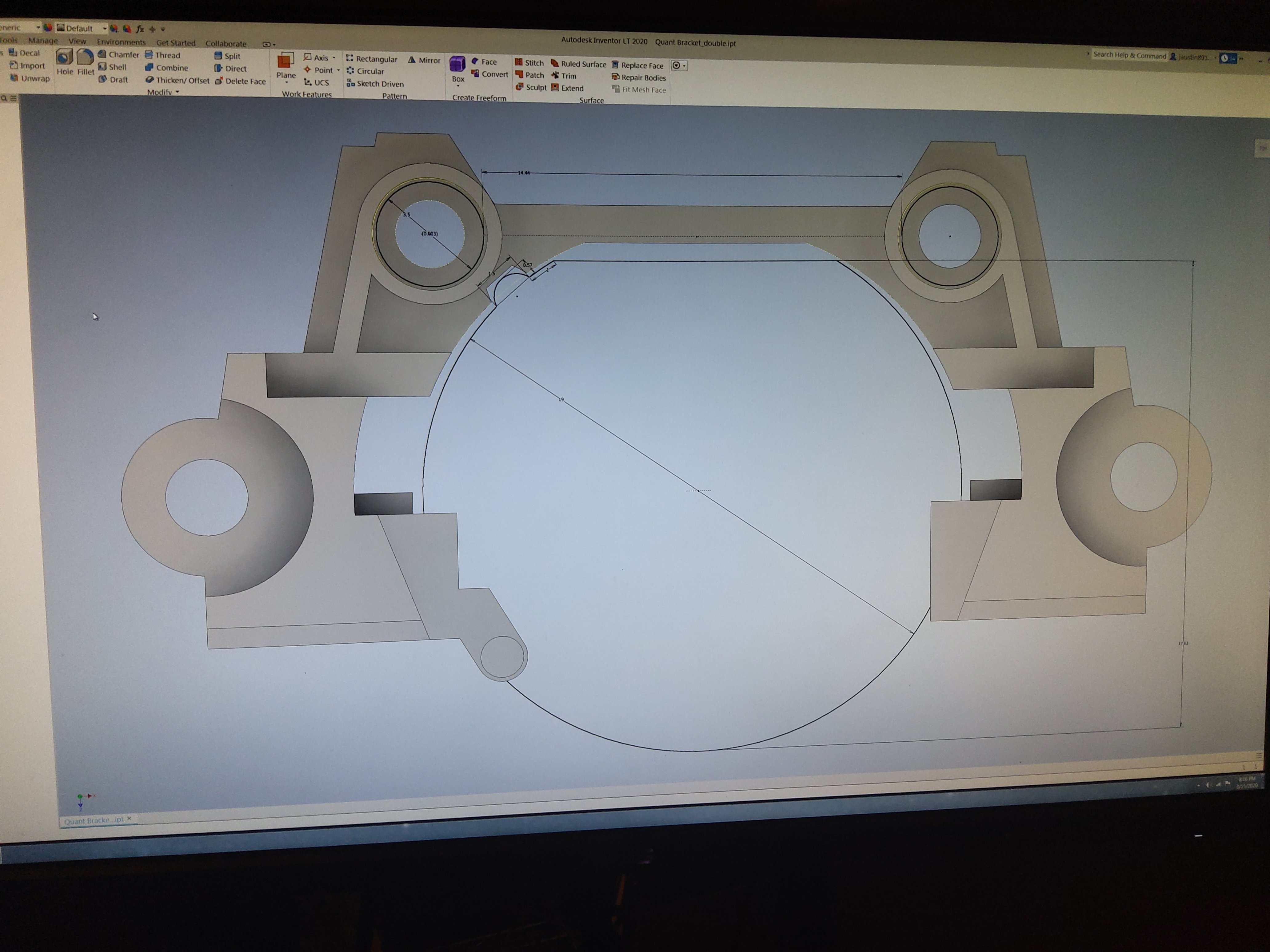
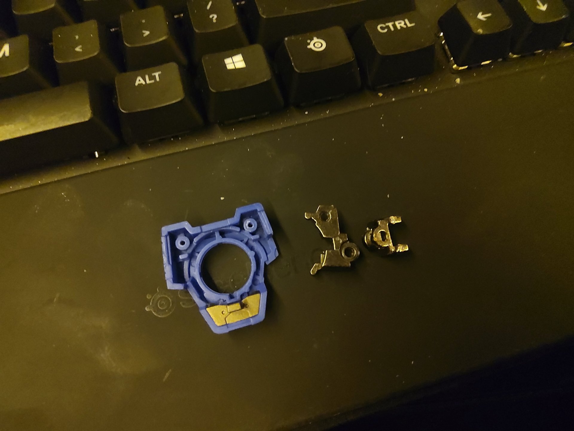
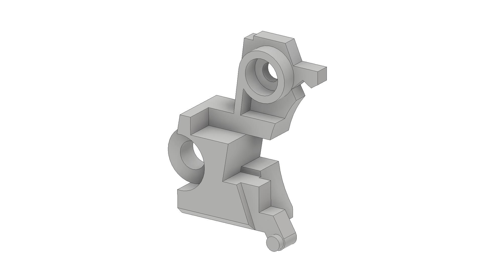
Thanks for the help. The past two days saved me ~$50 and a month and a half of iterating through shapeways; the money's relatively trivial compared to te rest of the costs on this project but the time it takes drives me insane. The nub and missing cutout on the mirrored side are fine. The nub is coming from just chopping off the lower portion of that side rather than checking the features in the shell; since I'm going to be cutting the shell off at that point anyway it won't be an issue. The cutout is for the indicator on the LED switch it's only present on one side; I know the original plastic inset on the other side has the same feature but it serves no purpose and is a potential failure point in printing/polishing so I deleted it. The shortness is concerning though; it means the radius that drives upwards of half the geometry is off. There's so many dimensions and constraints tied to it that trying to change it blows away the rest of the geometry. Fortunately I made a construction sketch of the drive body (Really should've thought of that earlier but I'm so used to being able to interrelate parts through the assembly environment It didn't occur to me.) and it looks like in theory everything will work with the existing radius though some areas are a bit tight. Should be close enough that I can just grind down a bit of the bracket if it doesn't fit. Now it's just a matter of if shapeways can print it accurately enough. Their page on the steel process says that the tolerances vary wildly and are unpredictable due to cooling shrinkage but can be as much as 5% which is massive compared to some of the margins I have to work with.

-
Symmetrical Gundam 00 Quan[T] Metal Build Mod
Jaustin89 replied to Jaustin89's topic in The Workshop!
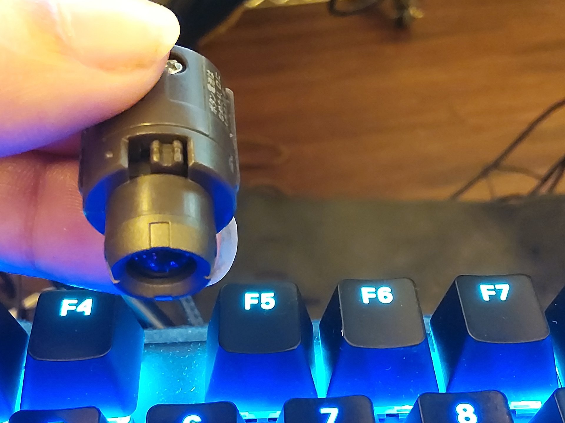
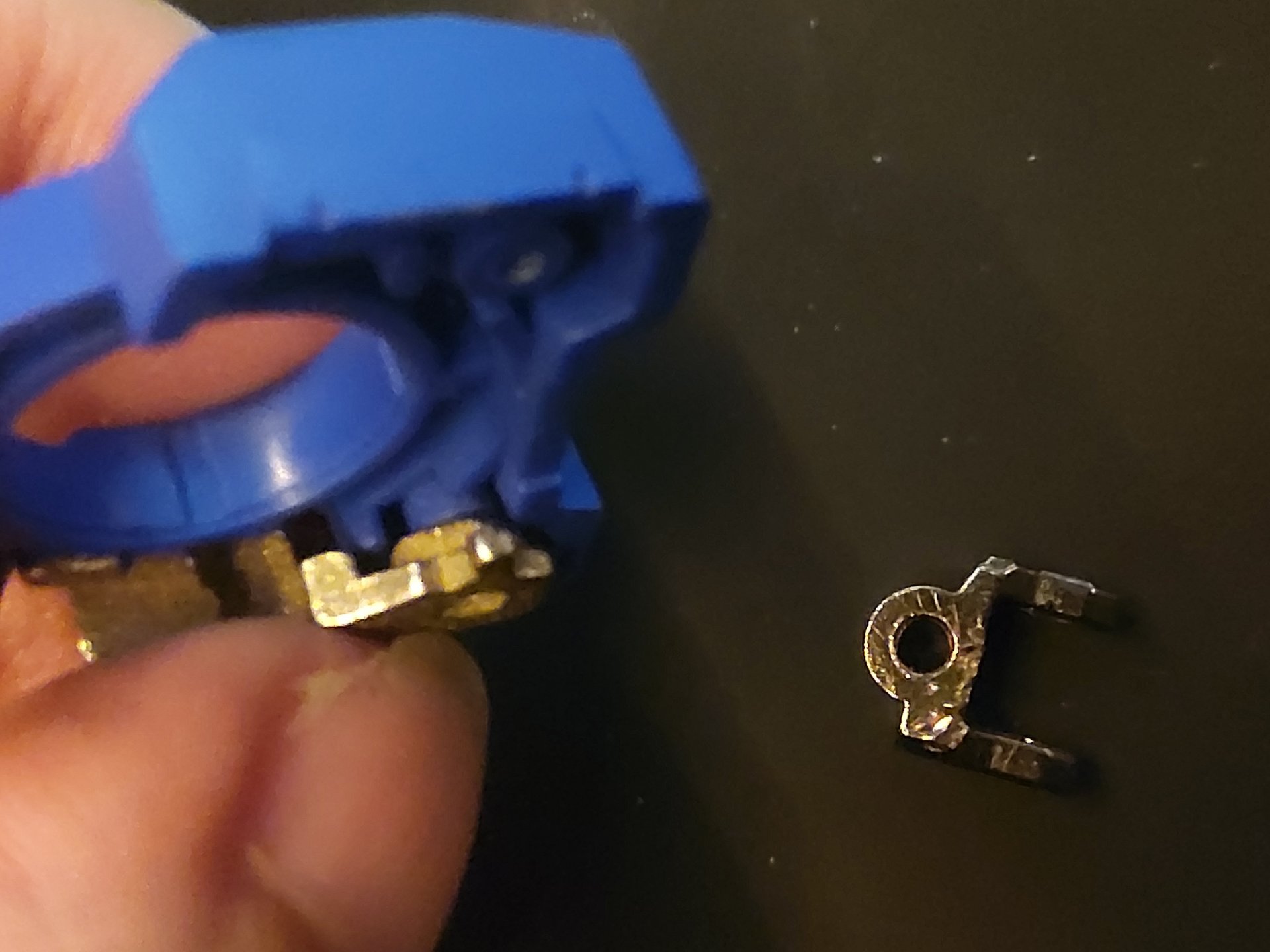
Awesome; thanks. It looks like the I.D. of that circular feature and the O.D. of the boss it fits around are tapered; I'm getting measurements from 3.55mm at the base to 3.75mm at the lip. It's probably just drafted for mold removal so I went with a straight I.D. of 3.75mm. Quant Bracket_double.ipt If you want to try that to see if everything lines up I'd appreciate it. Then I can get it ordered and find out if I have to adjust anything for the relatively low accuracy of the steel printing process. -
Symmetrical Gundam 00 Quan[T] Metal Build Mod
Jaustin89 replied to Jaustin89's topic in The Workshop!
Thanks for the offer but I had version 2 of the bracket and version 1 of the arm joint ordered before I even made the post here; if you want to check it out anyway I've attached the .ipt file. Quant Bracket2.ipt It's not my best work since I'm stuck with Inventor LT at the moment (Burning through my free trials before I bite the bullet and get a personal licence; might end up going Solidworks since it's a one time payment rather than a subscription but that's a good chunk of money.) and doing an assembly of the easier to measure parts to drive the bracket off of is a non starter but it's decent for what I have to work with. -
Symmetrical Gundam 00 Quan[T] Metal Build Mod
Jaustin89 replied to Jaustin89's topic in The Workshop!
Yeah; I'm replicating the existing parts as test print); once I get them working I'll print the mirrored versions. I actually might end up using the printed version of the first joint depending on how cleanly I end up separating the one from the second arm. As you can see in the third picture above I tore up this one pretty badly getting it separated and while it'll still function fine it looks like crap. I don't have access to a 3D printer; I bought a Prussa I3 kit last year and got it functioning but constantly re-leveling it made it too much of a hassle to use for the quality I got out of it and I ended up selling it. I considered getting a cheap printer or using plastic for the test prints but I figured it's better to work with the same printing process and tolerances to dial it in. Getting it printed in steel isn't really a whole lot more expensive than plastic anyway; that part was $15 in bronze-steel vs. ~$7 in plastic. -
Symmetrical Gundam 00 Quan[T] Metal Build Mod
Jaustin89 replied to Jaustin89's topic in The Workshop!
Bracket prototype #1 is a bust; doesn't fit either the shell or the first joint of the arm. It's fairly close for trying to model something that complex with nothing more than a pair of calipers though. It looks like I've got to open up the features a lot to account for the low precision of the printing process. I'll probably leave the holes for the pins as they are and drill them out to cause the kind of tolerances they seem to get in printing just won't work for a force fit pin. Now to revise the model and wait another month for shapeways to print it.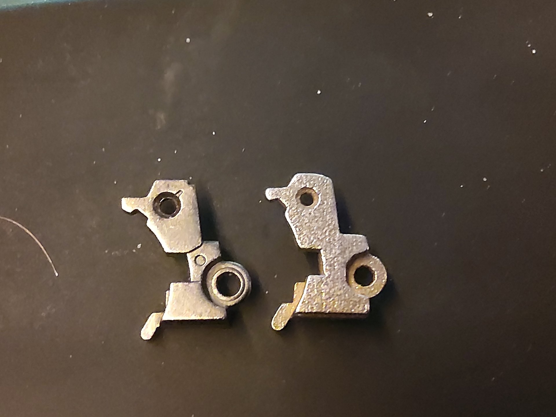

-
Aircraft Super Thread Mk.VII
Jaustin89 replied to David Hingtgen's topic in Anime or Science Fiction
Looking at that I'm gonna go with pop up splitters to stabilize the airflow around the muzzles so it doesn't mess with the bullets trajectory. With the position of the guns on the nose I could easily see the airflow diverting bullets a bit without some form of correction. Thinking about it I'm guessing that's also why most newer fighters have the gun in the wing root as the airflow is largely stable and in line with the plane's axis in that region. -
Aircraft Super Thread Mk.VII
Jaustin89 replied to David Hingtgen's topic in Anime or Science Fiction
Not sure where the hatches you're referring to are but looking at how the gun mounts I'd guess they're likely used to eject spent casings. Also it's not quite the same but the F-22's gun is fully internal with a hatch that opens to allow it to fire in order to minimize radar return. I'd guess the F-35A has a similar setup. -
Aircraft Super Thread Mk.VII
Jaustin89 replied to David Hingtgen's topic in Anime or Science Fiction
The snub nose on that radial engine plane is really throwing me; other than that I'd say it's almost dead on for an F4U Corsair. It's definately got an inverted gull wing but the only aircraft I can find that had that wingplan and had that short a nose forward of the wing root is the A5M prototype which had fixed gear. -
Your most recent Macross or toy purchase! General thread.
Jaustin89 replied to Gakken85's topic in Hall Of The Super Topics
My second MB Astraea finally showed up so I could get them set up (at least till the avalanche packs come out in a month or two and I can gear up all 3 of them).
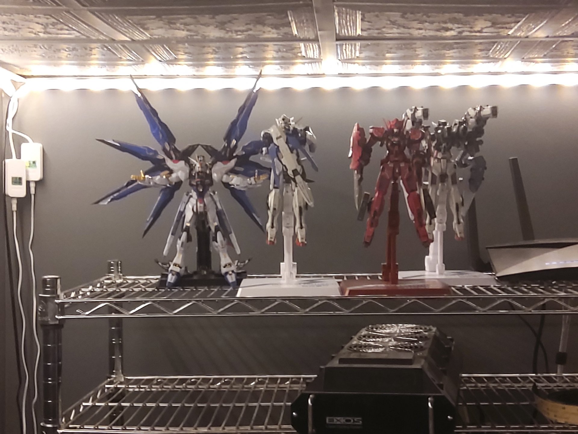
-
Bluefin may or may not do a US release. It's also currently still available at N-Y if you're willing to take a chance on it turning into a Kairos situation; the last couple P-Bandai releases haven't seemed to have issues but they also sold out in seconds where this has been up for a while. Edit: It's also still up on Nin-Nin Game though from what I've heard they've got a disturbingly high rate of "running out of stock" and canceling preorders only to suddenly have stock available at the current market rate.
-
Symmetrical Gundam 00 Quan[T] Metal Build Mod
Jaustin89 replied to Jaustin89's topic in The Workshop!
I'm still not sure exactly how I want it set up but the backpack assembly (the shield, the arm it's connected to, and the backpack itself), the left shoulder, and the sword are the parts I know I'm using. Once I get the custom completed I'll see if there's any interest in what I'm not using. I may end up keeping both and having a shield-less Quant in addition to the double shield one; depends on how it looks. -
Symmetrical Gundam 00 Quan[T] Metal Build Mod
Jaustin89 replied to Jaustin89's topic in The Workshop!
It won't; the Astaea has a completely different attachment method. Some of the product photos for the High Maneuver Test Pack option parts seem to indicate that they may include a mirror of the launcher mounting arm. If it doesn't I may end up making one but I'm waiting to see if they include it first. In the meantime the Astraea Type-F comes with a matched set of brackets (the same type the Astraea comes with to mount the shield) so you can do a symmetrical Astreae if you get 2 copies (or find a second launcher somewhere) and a Type-F as long as you don't mind the launchers sitting higher over the shoulders than they should. I'm still waiting for delivery on Astraea #2 but I'll grab a picture once I get it and attach the second launcher. -
I got my hands on the Quant and this is very doable. I started a thread in the workshop if anyone's interested in watching the progress so I'm not derailing this thread.
-
Not a Macross project but there's enough miscellaneous stuff in this section already I figure it's okay. I've never been a fan of strongly asymmetrical designs but liked the overall look of the 00 Quant otherwise; after seeing the Exia R4 and mentally overlaying it with the quant I decided to kit bash a pair of metal build Quants into a custom double quant. Still fairly early in the process as I just got my parts quant to tear down but this is looking verry promising. Stock backpack disassembled: The two metal pieces are handed and will need to be mirrored, and I'll need to cut the left side of the shell to match the existing opening on the right. Beyond that this shouldn't need any modification. I've already got the larger piece modeled and on order through Shapeways; once I get it and the second joint to assemble in place of the stock pieces I'll mirror it, join the tops to reinforce the structure (There's only ~.75mm available but with both sides screwed down it shouldn't see significant stress; it'll mostly just supplement the small protrusion the stock bracket uses for anti-rotation) and I should be all set to go. I'll try to keep this updated as I go and if there's any interest I can make the models available once I get it working for anyone that wants to mod their own.
-
Thanks, this is actually looking a fair bit easier than I was anticipating. I'd assumed the backpack was closed and sealed and I'd be destroying it to even get a look at the structure; but with that construction it looks like I should be able to fully disassemble it without damaging anything (provided nothing is glued in). Assuming what people are saying about the range of motion on the arm is accurate (and that seems to be the case based on the joints in those pictures) this could end up being as simple as pulling the arm out of a second Quant, grinding down that protrusion on the bottom, cutting an opening on the other side of the shell and installing the arm. Absolute worst case seems to be that I have to 3D print a new shell and a mirror of the metal bracket and re-pin the arm to the new bracket. It should be ~$30-50 through shapeways to print that in steel; expensive but fairly negligible against the cost of 2 more Quant's if I go through with this.
-
Thanks, it does look like it's going to need a new backpack design to accommodate the armatures. It also seems they're not mirrors; the design sketches on P-Bandai's page show the Exia R4's arm attaching at a ~45° angle vs. the horizontal attachment in the Quant which could make it tricky to accommodate both without looking weird. I ordered an R4 and the cheapest Quant I could find (~¥16000/$150 shipped); I'll evaluate whether I want to pick up spares and start cutting or resell them once I have both in hand.
-
Anyone with a 00 Quant willing to take some close up pictures of the armature for the shoulder attachment and how it connects to the backpack so I can get an idea of the level of modding I'm signing up for before I start spending money on this plan? I'm a mechanical designer so no matter how it attaches reworking it isn't impossible; especially since from all the pictures I'm seeing on product pages seem to indicate the repair 4's backpack/armature is largely a mirror of the Quant's which should eliminate the factor of prducing a mirrored armature. At worst I'd just need to dissect and splice the backpacks together. At the same time there's a reason I go for Metal Builds rather than model kits so if I'd need to really tear things apart and do a lot of finish work to get it looking decent I'm not sure the end result would be worth the effort and money (especially since my OCD won't let me cut up my only copy of something and I'm automatically in for two copies of each figure).
-
I've never been a fan of the Quanta design but that's just 'cause it looks horribly un-balanced; I'll probably get one of these and a Quanta in the hope of rigging up a mostly symmetrical Quanta with both shoulder attachments. If it works it seems like it should look like an actual upgrade of the 00 Raiser.
-
What Current Anime Are You Watching Version v4.0
Jaustin89 replied to wolfx's topic in Anime or Science Fiction
The original version of that is one of my favorite Shinkai works; not so much for the story but for the fact that he did everything but the female lead's voice (which if I recall correctly was done by his wife/girlfriend) himself. -
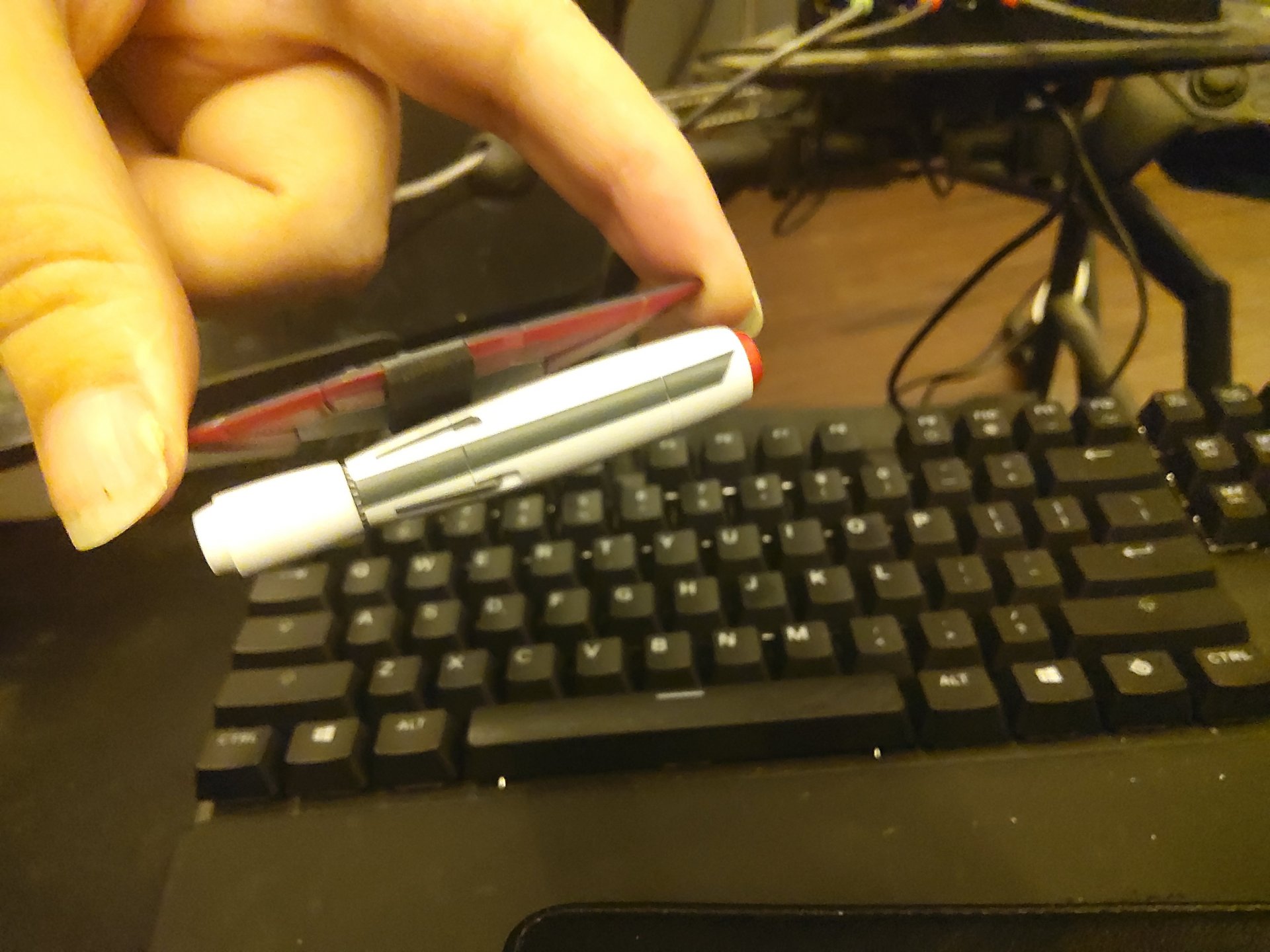
The prototype shield adapter came in and it works well enough to open the product on shapeways. https://www.shapeways.com/product/QXMNJYDW8/vf-31-shield-adapter-reeplacement I will note that it's not a perfect fit. You don't get the snap where it locks into place like the stock adapters do and due to the material the lip that secures it wears away after cycling it on and off a few times. It still works afterwards but can be shaken off the shield. I'll probably try to refine the fitment eventually but for now this should work.

- 20154 replies
-
- 1
-

-
- macross delta
- vf-31 siegfried
- (and 4 more)
-
I may have to make those two separate versions due to the geometry of the shield; I'll play around with the options and see what I can do.
-
Your most recent Macross or toy purchase! General thread.
Jaustin89 replied to Gakken85's topic in Hall Of The Super Topics
The driver for my old house never bothered to get out of the truck; with one exception every package that didn't fit in the mailbox we had to pick up the next day. That one exception was when I had a day off and was in the driveway when he stopped; I walked up and was handed a stack of mail with an already filled out delivery attempt slip. His response when I asked for the package was "Oh. Yeah, I guess." -
I'm hesitant to do the missiles for a couple reasons. One is the increased risk of running afoul of Bandai since their inclusion of the missiles is a selling point of the super packs or certain valks; offering a replacement option for people that lost or broke their adapter is likely a non-issue even if Bandai became aware of it, offering something they'd see as a product or potential product likely would be. The othe reason is the quality; an adapter you're not going to care if the surface is a bit rough or if it's a solid color, the missiles are something you're going to be looking at directly and getting any semblance of decent appearance out of a 3D printed part takes a ton of work sanding and painting. I'm not really comfortable offering something that I don't see as being able to meet my standards of quality. That said one of the projects I've been working on is a series of adapters based around the ones included with the YF-19; two of the pieces I've designed are that shield bracket but with either a pylon that matches the 19 missiles or the standard hardpoint in place of the peg used by the 31 reaction missiles. Once I have everything tested and any issues worked out we can get some pretty interesting setups like having the AMRAAM style misses from the 19 on the shield or a cluster of reaction missiles rather than pair (one of the hardpoint clusters from the post below mounted to the shield-hardpoint adapter). I'm just working on it in my spare time so it'll take a while but it's in process. Thanks. To me a model like that is pretty trivial; I'm a mechanical designer in the aerospace industry so I deal with far more complex modeling than that on a daily basis. It's been a while since I made it but I think I spent an hour on it at most.
-
Yes; I've got a pair of precision calipers that I use for whatever measurements I can, though on something like this I have to do a lot of eyeballing because of the curves. Between slight inaccuracies from that and the difference in tolerances between molded and printed plastic it's entirely likely I'll need to tweak the design; Bandai seems to use tolerances on their peg joints which typical 3D printing just can't match yet.
-
Your most recent Macross or toy purchase! General thread.
Jaustin89 replied to Gakken85's topic in Hall Of The Super Topics
https://www.magellanmodels.com/nasa-saturn-v-rocket-large-scale/?gclid=EAIaIQobChMI_p7P86Xw5gIVjP7jBx1Pbw6eEAQYBCABEgIszfD_BwE Magellan's got one at 1/100 coming out soon but I can't justify $500 on it when I don't have the space to display a third 3-4 ft long rocket model (I've got their 1/100 Atlas IV and the lego Saturn V is ~1/110).