captain america
-
Posts
3539 -
Joined
-
Last visited
Content Type
Profiles
Forums
Events
Gallery
Everything posted by captain america
-
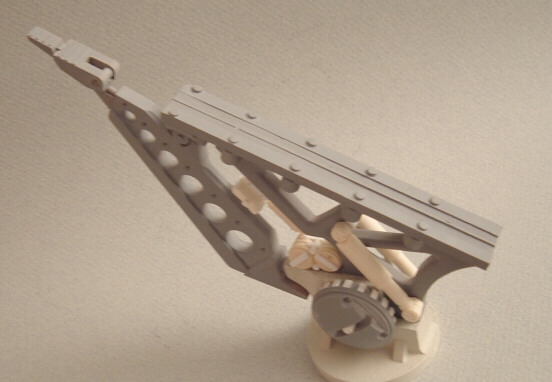
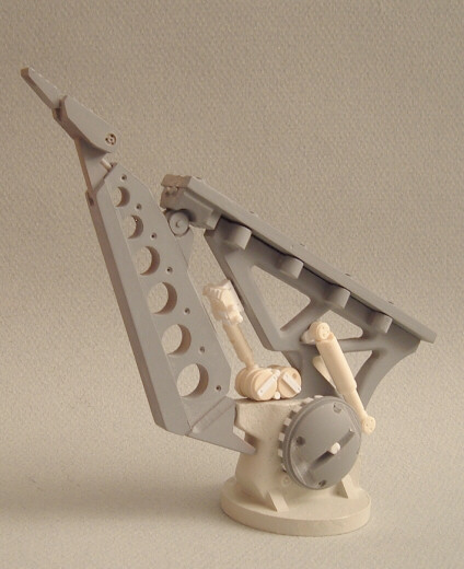
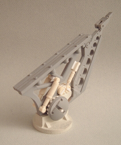
Hi Super O. Actually, the whole point of the launch rail/base is that it MUST be strong enough to support the weight of the finished booster, and it will--> see pics below. Regular resin would've been too brittle and insufficiently strong to do the job, so I switched to a high-impact, high strength polymer in which to cast the base and part of the support pylon. The down side of this is that this material is more expensive than regular resin, but it sands/putties/machines every bit as nicely. The central column part (with the 3 triangular openings) is set to be cast in metal for oprimal strength, but I'm still going to experiment with the new polymer; the stuff is so tough that it might very well be strong enough to cast the main support in as well.
-
Hi Tony. Yes, the podium will definitely be included with the launch rail. I'll post some pics of it later this week.
-
Hi guys. Let's see, where do I start... Firstly, much to my own chagrin, the booster pylon doesn't swivel up or down: because of the relatively heavy weight of the booster unit, and the thin cross-section of the launch rail would have made the model dangerously unstable if I were to allow it to pivot, so I decided to make the launch angle fixed. Also, as the booster unit is VERY back-heavy ( full resin nozzles, versus a VERY light plastic kit at the front) makes the whole booster assembly want to fall on its tailpipes, even in full horizontal. Therefore, I'm designing the whole thing to mount to the launch rail via eight hex-head screws, to hold the booster firmly in place. I suppose that you COULD unscrew the vehicle and remove it once complete, but generally, I'd tend to say that it should be affixed permanently for stability reasons. Price: the launch rail/pylon is seemingly going to be about the same price as the booster; I think it's set at $105, but that will include the paypal fees. The fact that there will be about 14 screws, metal cast parts and wires, not to mention using a slightly more expensive plastic all had to be taken into account financially.
-
Also... It was decided that the launch vehicle, because of its extreme size and cost, would be offered in two components: the first being the launch rail/pylon assembly/podium and then after, the launch vehicle itself. The idea behind this is that firstly, it helps to defray the cost of the whole shebang into much more affordable segments for those who want the whole booster launch system, but also, for those who may not have the means to afford /don't want the whole monty, those customers may simply want the booster and then use the launch rail as an elaborate display base.
-
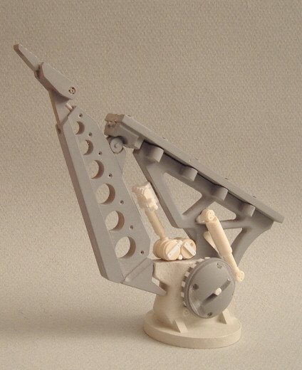
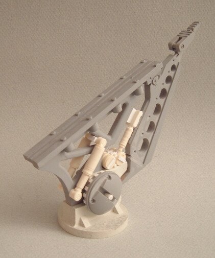
Last pic. The raised, circular locks are designed to mate with the recesses on the lower fuselage of the booster. As the booster kit itself is rather heavy, new-generation polymers will be used in the launch vehicle castings for extra strength.

-
Pic 2. Though it's not finished, some of the detailing I've opted to enhance are more subtle, like the rough, cast texture of the main pylon; giving it a sturdy, "tank turret" heavy steel cast look.
-
Hi all. At the request of Samurai Monkey Models, I'm posting some preview pictures of the 1/72 Launch Vehicle for the Valkyrie Booster. The core of which is the launch pylon/rail, atop which the Valk and booster sit. The detail herein was extrapolated as best as possible from the singular (and minuscule) sketch of the launch vehicle. I've also obviously improvised to fill-in the gaps in the structure that were not visible, and unlike the Booster unit, the Launch Vehicle will be much more "mixed media", making use of not only resin, but also metal cast parts, steel screws and wiring accessories. Cheers!
-
Primer is useful at providing a nice, matte surface color that allows you to spot flaws more easily. However, primer also has a secondary purpose: helping paint adhere to a given surface or providing a barrier coat between the paint and the surface. If you're using model paint on a plastic model kit, you generally don't need primer. If you're unsure about some seams that you've filled, you can just "spot-apply" primer in those key areas. However, if you want to use automotive paints, or industrial finishes on your plastic model, you have to prime, otherwise the strong solvent in the paint will attack and craze your plastic. Resin kits: generally, I'd recommend at least a quick primer coat, just to help spot any minor flaws, like tiny pinholes you may have otherwise missed. However, unlike plastic, the nature of polyurethane resins allows you to apply pretty much any paint, hobby or industrial, right onto it without problems... Just make sure you washed /lightly sanded the part carefully to remove any residual mold-release.
-
Hi Carl. As a rule of thumb, I try to avoid the use of metal in kits unless it's truly needed as a load-bearing structure, like say the launch rail/pylon for the VF-1 booster. Typically, metal shrinks at a different rate than resin, and for certain parts can be tricky to incorporate these 2 materials together with regards to fit. However, my train of thought is simply to do whatever is necessary and best for the sake of the kit. Somehow, I get the strange impression that Hasegawa might not tackle the GBP1. Though it's still very much a possibility, I think that I could still offer an interesting take on the design. Variable VF-9: it would take about as much time to engineer the transformation process as to sculpt it, and would be VERY expensive as a result. In thus, I'd prefer to start with a few more moderately-priced models. At least up until Samurai Monkey can attain a good reputation with regards to quality/craftsmanship, and gain a broader client base that would make sculpting/selling such complicated models more worthwhile.
-
Please bear in mind that the project mentioned above will follow the VF-1 Booster launch vehicle, and will probably be scheduled for late December at the earliest.
-
Actually, the price quoted was for the GBP-1 (tv/film) armor, not the TH. Looking at the complexity of the TH unit, the same scale kit could cost as much as $50-60 more. Though small, a lot of the parts in the shoulders & legs would be very small, thin, and very tough to cast ( more reject parts, lots of parts, longer production time per kit, etc.) There's always a chance that I can end up doing it for cheaper, but I usually want to prepare clients for a worst-case scenario, and if by some magical twist of fate, it takes less time/effort/material than I planned for, I just re-adjust the price of the kit accordingly.
-
1/72 Valkyrie Booster instruction manual.
captain america replied to captain america's topic in Model kits
*bump* I was wondering if the mods could pin this post, even if only temporarily? Just long enough to allow customers have access to them until the final model are shipped. Thanks, -
Hi guys. I've compiled a quick list of the projected prices for each model in the list, as well as giving an approximate size to the more ambiguous skus. The prices are all based on the (percieved) complexity of each sculpt, the amount of material needed to make it, as well as rough mold material costs and a few other things. Also, this would be for a projected run of about 50 piecs. 1/72 Regult: $180-190, @28-29cm tall. Free pose, cockpit detail 1/72 Glaug: $280-300, @35cm tall. Free pose, cockpit detail human sized gun pod: $350, 60-65cm long. Non-firing, collapsible 1/72 Zentradi soldier $50-55, @ 12.5cm tall. Static pose, clear visor Nousjadeul Ger TV/film versions: $180-190, 22-23cm tall. Opening cockpit hatch. 1/72 VF-17 $190-200 1/72 GBP-1 $110-120 1/72 VF-9 $215 --The term free pose indicated that the model may be built in the builder's desired pose, but is not poseable once complete. --Fixed pose means that the model can only be built in the pose it was designed in.
-
Hi Onezero. Glad you like the kit. You're absolutely right about the undercuts in the nozzle, and let me tell you that my fingers were quite raw from wrestling with the casting, trying "gracefully" to extract it from the mold everytime! Surprisingly though, the molds seem to be good for about 25 castings, which was a bit more than I was expecting. Good mold release was critical for this however, as I don't think I would have been able to pull even 10 out of that mold without any release agent.
-
The only "modification" needed to the Valkyrie kit legs are the deletion of 2 parts, but this is clearly outlined in the instructions. You can always just clean out the foothole with a dremel and file if you insist on keeping all the parts. However, the castings that Jesse is doing seems to have alleviated the issue of the foothole, so for those castings you may not have to modify anything.
-
It would be a bit tough to find 100+ orders for an expensive toy conversion of a subject that isn't cannon. Besides, the silicone molds from which the castings are produce will typically have a life of about 35-50 pulls. Afterwards, you have to re-tool, and that in itself incurs cost. The $250-300 price tag would be for the TH armor only, no fast packs...They could be offered pre-pigmented, with only minor painting required. To take existing FPs, disassemble and mold/cast them would cost more than buying the whole FP kit, so it's easier for consumers to simply procure their own, and paint them.
-
The question that really needs to be asked is : would you still want a Thunder Hammers 1/48 conversion if it were (realistically) priced at $250-300? Though it looks simple when all the panels are closed, the TH armor is actualy quite complex, with thinwall panels & undercuts in the shoulder module, and a skeletal frame for the leg armor comprised of both rods and oddly-cut thin cross-sections, and then there are all the missiles. Long sculpting time, coupled with those thin, hard-to-cast parts = expensive model ( or at least it'll be expensive if you hire competent professionals.) More so if all parties have to turn a buck over a very small production run. Food for thought.
-
Very nicely.
-
Hi Lu. Not bad, not bad. I get the impression that you've been sharpening your painting skills lately, and it's starting to pay off. Just make sure no one ever finds out what you did to those poor FSS models, or they'll lymch you Next time I stop in, maybe I can give you a few painting/weathering pointers. Quick things, that'll make a big difference.
-
Last one for now. Guys, feel free to post pics of your own buildups! Let's see some of that creative painting and detailing
-
Another pic.
-
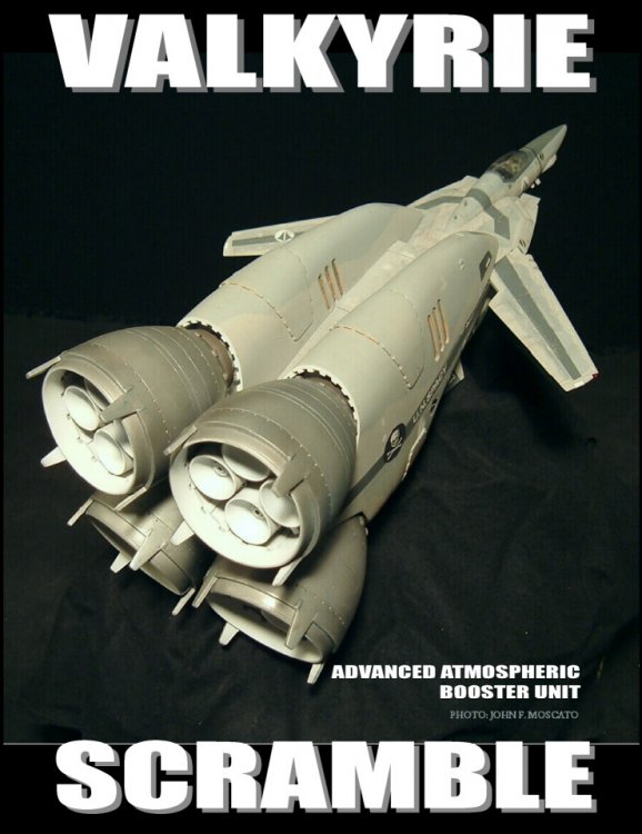
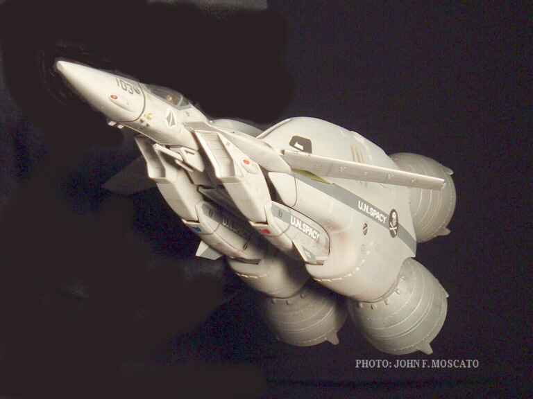
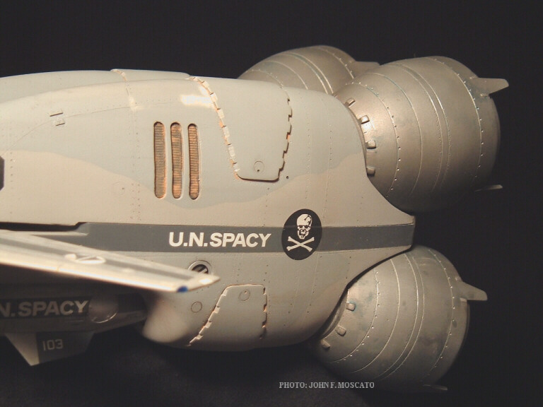
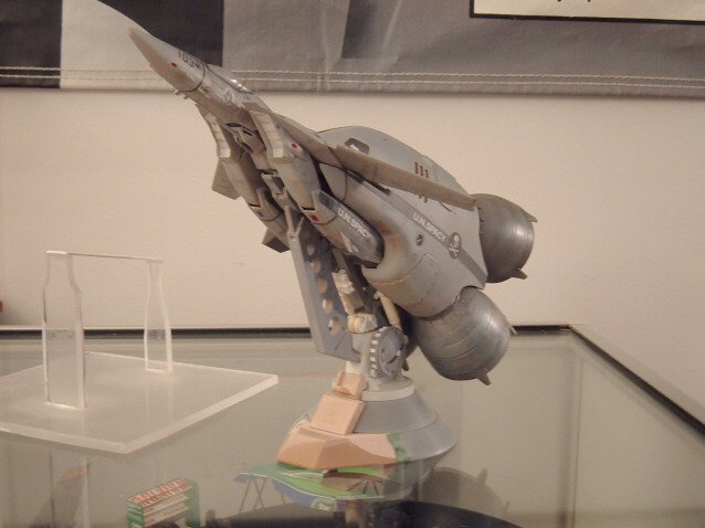
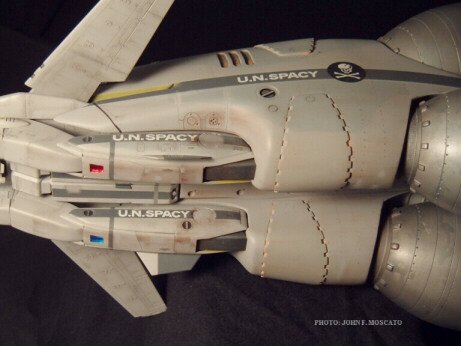
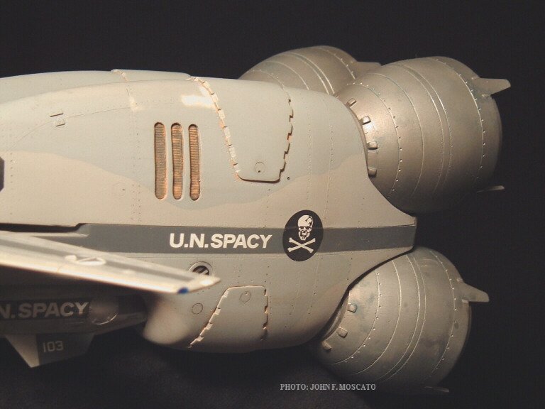
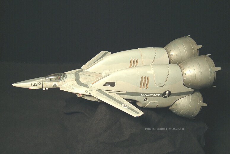
Close-up of the port-side fuselage and vents. Rust detail was added with chalk pastel in order to give the booster a different weathered look from the fighter, since I immagined that both units would have been used and maintained differently.
-
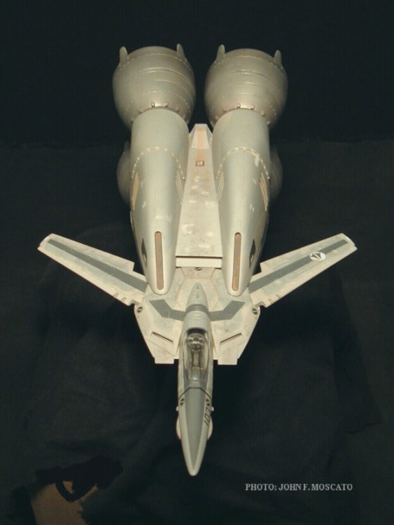
Top view.
-
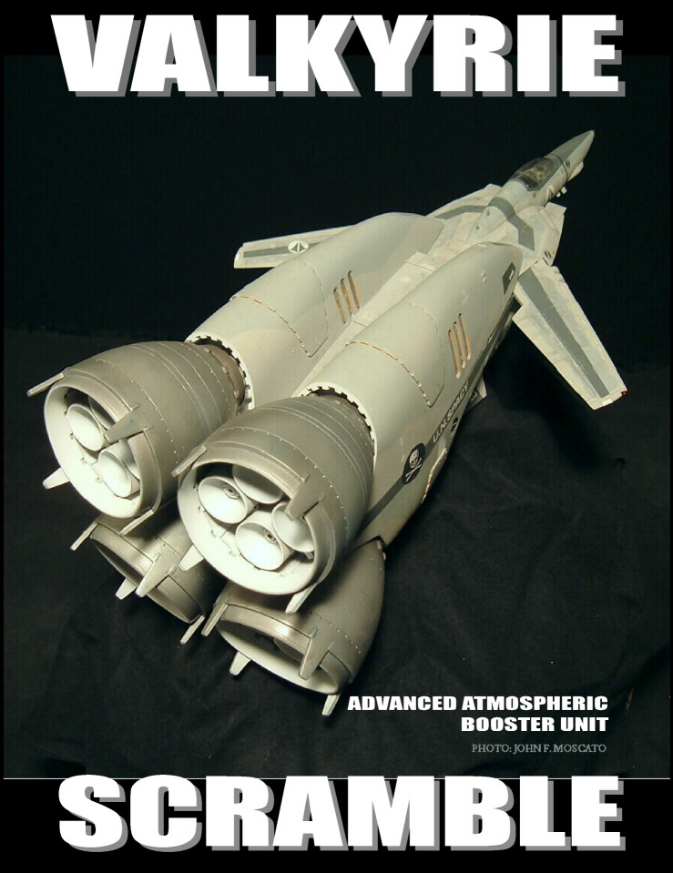
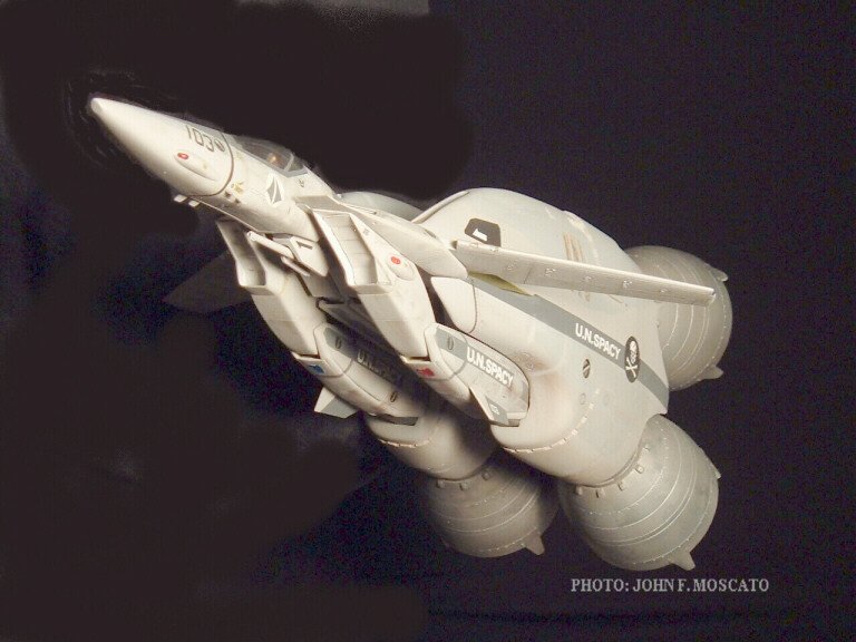
Hi guys. Just thought I'd start a thread exclusively devoted to promote the VF-1 Booster project. Essentially, this is the grand-prize buildup in its finished form, and hopefully, this will give a good idea of what can be done with the kit. Enjoy.
-
...And here's a little promo poster I whipped-up.