captain america
-
Posts
3541 -
Joined
-
Last visited
Content Type
Profiles
Forums
Events
Gallery
Everything posted by captain america
-
next
-
next
-
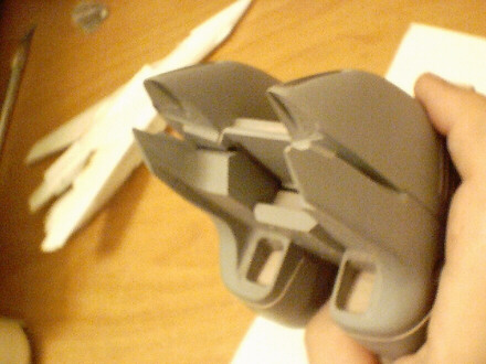
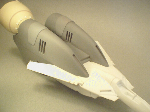
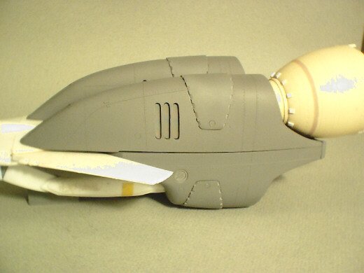
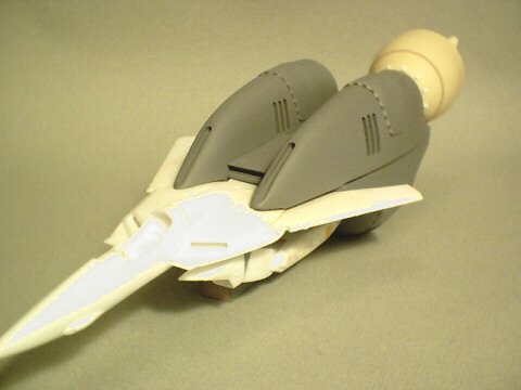
It's finished. As you've most probably assessed from my previous updates, my pictures are simply poo, and I appologize for that ahead of time; there's a great deal of very fine detail and scribing that isn't really clear in the pictures, but I assure you that it is indeed there. The large gap running horizontally fore-aft along the outer hull is simply the junction between the upper and lower hulls. I didn't glue the parts for the photos, as this would damage the masters needlessly. Now that the masters are done, I'm tasking myself with making the first set of master molds, and the test-shots that will lead to the actual finished castings. These should be done by Sunday of next week... Depending on how quickly my mold material is delivered. Hopefully I'll have a new (proper) camera to take better detailed pics by them.
-
Alas, I think this thread's taken a step in the flame direction, and there's really no ned for that. The mystery of the golden VF has been solved; no sense antagonizing each other over a bad joke, this is MW, and we're better than that. Mods, can we please get this closed before it gets ugly? Cheers,
-
Hi Guys. Quick, pictureless update. I'm actually almost finished with the masters at this point; I had a minor hiccup with some parts that I still need, which is putting me a bit behind schedule, but all that said, the masters for the booster will be finished on Monday, and I'll have a full picture show then.
-
If you really want to pressure-cast, you can get a brand spanking new 2.5 gallon pressure tank by Campbell Hausfeld from your local Home Depot, or equivalent home renovation chain. Great big $80 US/$120 cdn, and it can safely take pressure to 50psi without batting an eyelash. If you need more than 50 psi of pressure to get decent castings, you simply aren't doing it right. Vacuum pumps & chambers: you can get these for a song on E-Bay compared to what I paid for mine 7 years ago. A lexan belljar & base are what the simplest vacuum chambers are made of, and they work flawlessly if not mangled or abused. As for CNC machining & 3D modelling. Pure overkill. Unless you need aerospace tolerances, and display models don't, you can get absolutely superb masters sculpted by hand for a fraction of the price.
-
Hi Eric. There's currently a raffle going on as we speak. Basically, you have the possibility of winning the VF-1 Booster with a Valkyrie, all built & painted by me as the grand prize. I believe that all the details were made available by MonkeyN at the very beginning of the post. And yes, if the booster sells well, I can't immagine why we couldn't organize the same type of raffle for a built-up launch vehicle later
-
Almost attempting to take credit for someone else's work?...Not the best way to introduce one's self to the MW forums
-
Hi guys. Mechamaniac: in so much as a 1/48 booster would be both enormous and hugely expensive, absolutely not. Major: yes, you read correctly. Though the production of the launch vehicle will be predicated on sales of the booster, it looks very promising so far. My only real concern will be price control, as the launch vehicle is a surprisingly-massive little bugger at well over a foot long.
-
Hi King Nor. How much the job will cost depends entirely on what you mean by "touched-up." There are quite a few talented modelers/customizers here who can help you out with that. Additionally, I think that there's an aftermarket decal set designed purposefully for the Yamato VF-1. Either way, you're good to go.
-
Hi Rob! Congrats on the new baby girl!!! I'm sure you'll have your hands full with your new bundle of joy, so don't worry about this little trinket; I'll get it done in timely fashion. Besides, you're probably running on lack of sleep from caring for the baby... Cranky as you may be now, you'll look back on the sleepless nights & diaper-changing fondly in 20 years
-

-
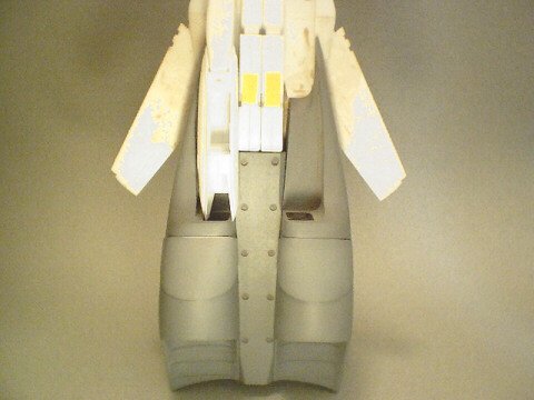
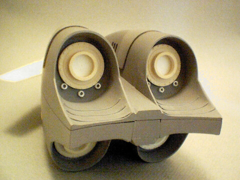
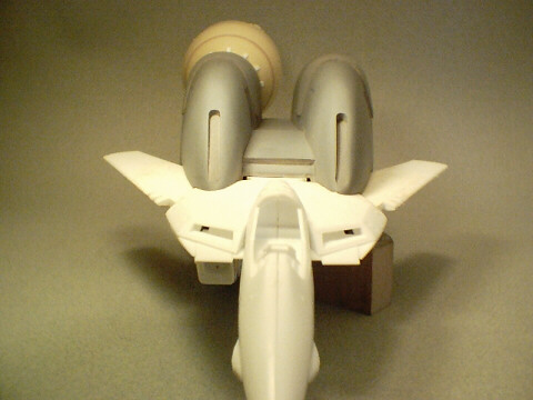
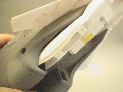
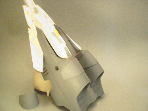
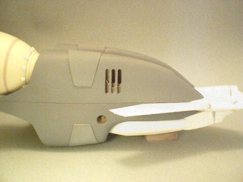
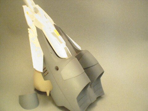
Hi Chad. Yes, Jesse will be doing the bulk of the casting. However, I plan to also make a set of master molds here; particularly for the nozzle/endbells, of which 4 will be required per kit, and because of the high detail in the nozzle area, I'm relatively certain that the mold-life will be far lower than normal. Also, in order to avoid having people impatiently wait months for their kit, Jesse and I can do double-duty, so that kits are delivered more quickly, or in case Jesse just simply bottlenecks from workload saturation. Oh, just for fun, here are a couple of fuzzy, low-quality pics of the Valkyrie mooring point... Simple as it looks, you guys have NO CLUE what bloody hell it was to make.

-
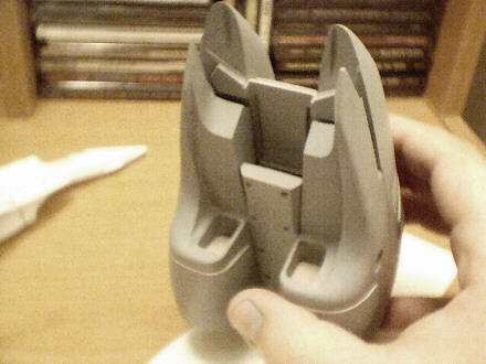
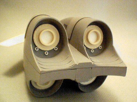
Hi WM. That's an excellent idea actually. I'll try to include the bent knee parts in the booster kit (depending on if I have any leftover mold material when the main parts are molded). Teeth around the endbell openings: yes, I'll be getting to those in due course. I was initially hesitant to add these, for fear that the gap between the housing and the nozzle would be too constricted and result in binding, but upon more extensive fitting & fiddling, it seems that I have adequate room to add the extra detail and still have plenty of room to adjust the angle of the nozzle.
-
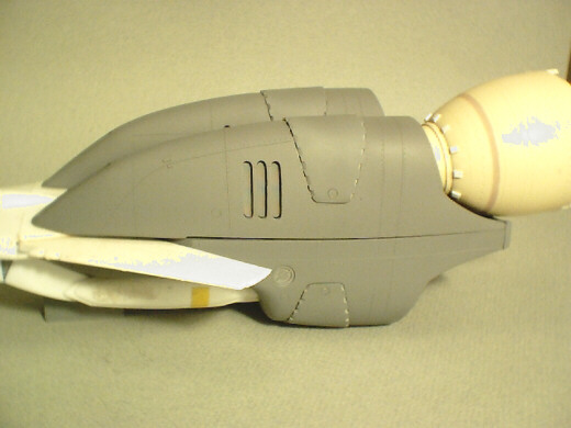
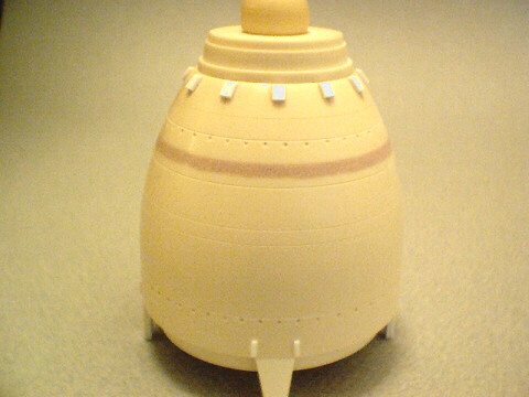
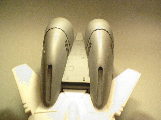
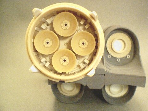
Hi Chad. Yes, that's right, my bad Basicaly, I'm just in need of the bent-knee part. I kneed to mock up the leg precisely so that I can adjust the hull beneath it and skirt the outer surface more precisely to its contour. As for detailing, the rivets on the bell itself are actually indented; I machined two different sized punch tools to do this more quickly. The lines (horizontal) on the endbell are also scribed. I did those on the lathe for precision. As for the raised ribs in the nozzle wells, those are quite simply strip styrene, as are the little rivets on the nozzle coupling. You just drill a small hole manually, and insert the piece of styrene.... And then do it 200 more times
-
last pic for this update.

-
next pic
-
next pic
-
next pic

-
next pic

-
next pic

-
next pic
-
next pic
-
next pic
-
next pic