
kyekye
-
Posts
619 -
Joined
-
Last visited
Content Type
Profiles
Forums
Events
Gallery
Posts posted by kyekye
-
-
Where does it say the stand is included?

I kinda assumed it.
It says " 1 set of weapon is included' and 'Exclusive Stand'
So that stand IS a 'product' and I thought selling that stand separately doesn't make much sense. So I assumed it's included.
It still could be.
-
How are you going to power all of these LED's? Switches are going to have to be hidden EVERYWHERE!
I have a collection of tiny switches of all types
 I have some good ideas about where and how to place them. but can't say if it works until I actually try it.
 -
Anyone noticed that 'U' shape clear display stand that will be included?
-
3-day weekend is over now and it's time for update!
I thought I spent good amount of time on it. but the progress doesn't look much.. so many small details! (and I spent some time doing family thingy and watch movies and play some games..etc)
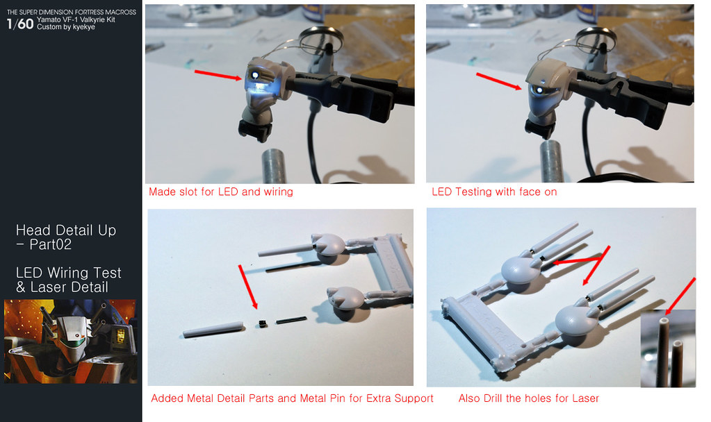
Anyways, I added a little more detail here and there on the cockpit. Also tried Vernier thruster detail up. Originally I was gonna use metal vernier parts for this, but tried plastic version for the front one (+ small metal part)
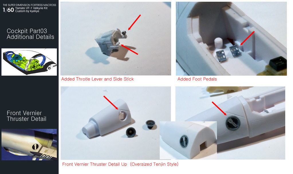
I'm waiting for some material delivery for cockpit and canopy, so I jumped to the next part. -Head!!
My goal is to add eye/visor detail + LED light, and add 1 more neck joint. You can see where it's going below..
Clear Visor part will be done with canopy when the material gets delivered
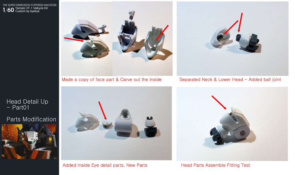
Quick LED and wiring test. Also notice the sensor slot on the forehead.
Added metal tube and metal pin for detail up and increased parts strength on the Head Laser Cannon. (I always scared of rotating them when transforming it) Also drilled tiny holes at the tip of laser.
I spent some time making silicon molds and parts copies for next step.
*notice the copy of shoulder hinge? - Now I can make endless supply!! (For this custom, I'm gonna strengthen it with metal sheets so that I won't need to worry about broken shoulder.)
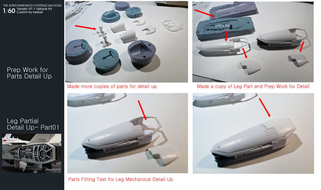
I wanted to add some mechanical details on one side of leg (like 1/48 Hasegawa model), but the sliding structure of inside the leg parts are too delicate and complicated. So I decided to do only the lower portion.
I'll scratch build the inside mechanical parts and attach the cover with magnet later.
That's all for this weekend! Thanks for checking it out!~
-
I'm really impressed that you got a 1/1 scale figure to match his height perfectly.
Haha I paid extra attention to make him shorter than regular 1/6 scale figures!!
:lol:What? You mean you have a life aside your hobby?

We'll wait, I think no one here wants to see the project spoiled.
Man.. I have too many hobbies aside from this model building.. Sometimes it worries me when I see my mancave.
Awesome work kye! I aways wanted to do something like that, but never have the time or telent. Hopefully one day I will have the gut to try and do some custome.
I also admire everyone here at MW, so many talented folks here!
Starting is important. Once you start, you can't stop!
-
Brace yourselves, week-end is coming (ok, tomorrow evening
).Sorry to disappoint you, but we have memorial day 3-day weekend until Monday

So.. next update will be Monday night!
Here is my old 12" figure custom I did a while back. Enjoy until my next update!~


-
Not all. My guess is the most of the colors will be painted/printed except for the logos. I Think its good idea for the people who thinks its too much.
-
It says 30th logo and all title logos will be water decal
-
I'm getting one just to celebrate the Yamato-Arcadia saga!!!
-

Hoooooly sheeeeeeeeet.


This has become my favorite MW thread!!!!
I can see the finished product is going to be mind blowing. I like how the instrument panel is turning out already.
Thanks for pretty pics and comments! Great encouragement!
Seconded.

What type of battery are you planning on using for this? Assuming you're going to use a small button-cell, I can think of a few places to put something that size. The trick is just working the wiring in.
Since you've got so many separate components, I'm guessing you'll need separate batteries in the nose, each leg, and the main body. You can probably fit a battery inside the nosecone if you cut away a little of the cockpit pieces.
The backpack probably has plenty of room for the power source for the wing and tail lights as well, though running a connection through the backpack joint might get tricky. Guess you could replace the existing hinge pins with copper, and just make a rotating contact, but I don't know if it'd be necessary.
If you modify the rear landing gear to rotate and fold like they're meant to, and use a collapsing piston like you made for the front, you should have plenty of room in the leg powering the lights there as well.
The big question now.. are you going to give this same treatment to a set of strike packs?

Current plan is to group them by function (A: landing/flight signal, B: Console, ,C:Power..etc) . I don't worry too much about wiring, but finding spots for switches (and cleverly hiding them) worries me a little.
Rear landing gear wasn't part of my plan (except for adding cables), but I'll need to look into it for the extra space. Thanks for the tip!~
That is insanely cool, you need to post a pic of it sitting next to the unmodified too to really show the differences
Oh yeah. I gotta do that, I guess. Next time!
amazing work! Have you thought about adding a thin film of something like wax paper between the instrument panel and the LED to diffuse the light a little more evenly?
The decal is applied on thin clear plastic cut-out shape, so I can just sand a little to get that effect. I also gotta block the light bleeding somehow.
just caught up to reading this thread. I hope you have it finished before MW Con 2013 in October!! i'd love to see it in person and this could definitely be a top contender for our annual Macross Customs Contest where you can win prizes!!!
AMAZING WORK!
Thanks for the idea, but I doubt this will be done by then - working only over the weekends. Also my contest days are over
-
Another slow progress...
First, the front landing gear. I needed to do this first before getting into the cockpit detail.
I drilled 1mm hole on the side of diecast and cut out the space for LED wiring. Made 2 parts small actuator and attached using 1mm screw. Added LED and lens. The light is bleeding out too much, so I'll cover the backside with something.
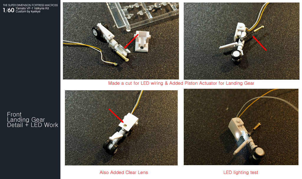
Now that I clear the bottom gearbox, I can start working on the cockpit parts.
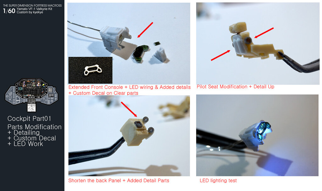
Like I mentioned earlier, the parts position need major shift.
- Extended the front console and added some details + LED wiring.
- Shortened the back part and added detail parts
- Shorten the seat height and added some details
- Made custom decal for console + Added bottom part
New parts layout and quick fitting test
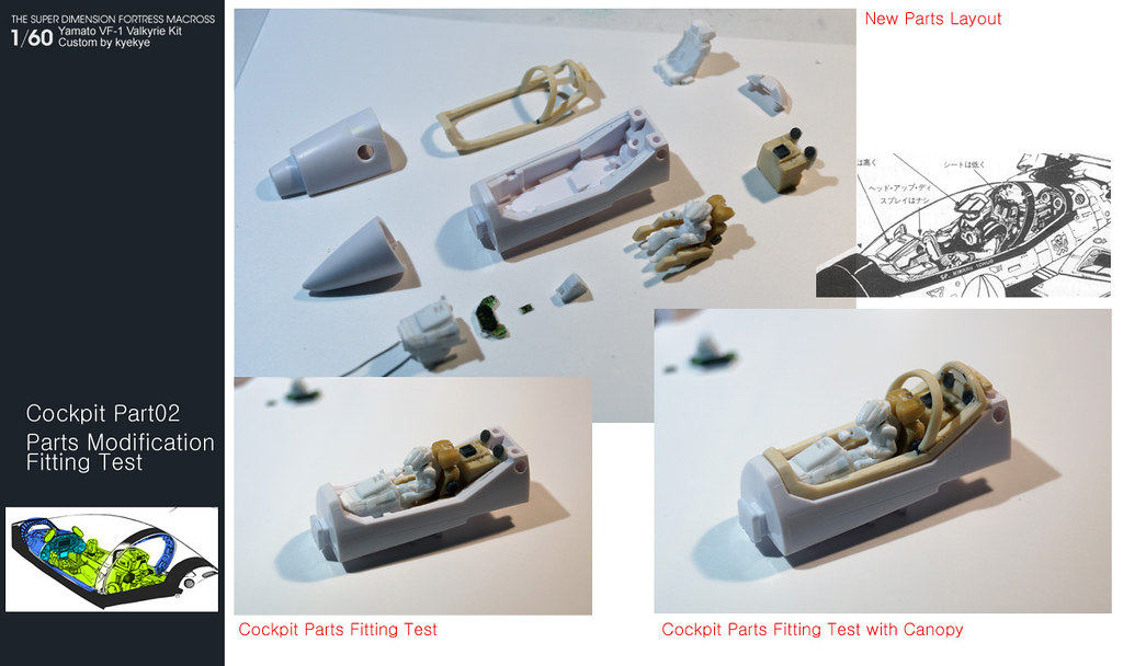
That's all for this weekend.
More work (such as PE parts, other custom decals..etc) will be done on the Cockpit during painting pass.
Now I gotta find some space for battery and switches.
-
Thanks again for keep checking the thread and leaving nice comments!!
just perfect you should make conversion kits availables

Full conversion kit will be difficult, but I might be able to duplicate some modified parts later.
How do you do those cut-outs so perfectly?
Hmm.. It's not really perfect, but this is how I do it.
1. make holes on corners with 0.5mm drill
2. use Photo-etching saw blade to cut it
3. use micro-file and sanding stick to clean the surface
-
So this is not the kit version? And you repainted it!? It came out pretty clean! Nice job.
Did you have to disassemble some parts for repaint?
-
There is a Sweets & Bikini Version mentioned in the tweets. Does this mean we get VF-1 dressed up with an over sized Meldrandi bikini?
That would be their current flagship product Super-Sonico sexy doll! Hopefully not for long!
-
More pics at Master File Blog
Every bit of each area is off in strange ways..


These are prototype- meaning 3d printed or test run. So don't mind the parts fitting or smoky glass part..
-

Quick notes from info (nothing really new)
*Mr K joined Arcadia (possibly as a contractor - or part-time) He mentioned 'irregular appearance', but I'm not sure if he meant 'at the office' or on 'Tweeter'.
*Nothing on Shizuoka Hobby Show, but will show something at Wonder Festival.
-
Design and transformation was reviewed by Kawamori. What happened there?
Maybe He was paid to do review on early stage only?
-
The one on the left?
-
Those panel lines on chest and intake are just wrong... I might cancel my order....
-
Another busy weekend doing family thing (meaning less time on this project..
 )
)Here's my mini update.
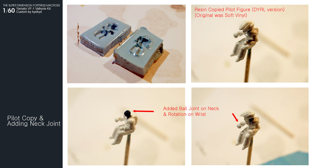
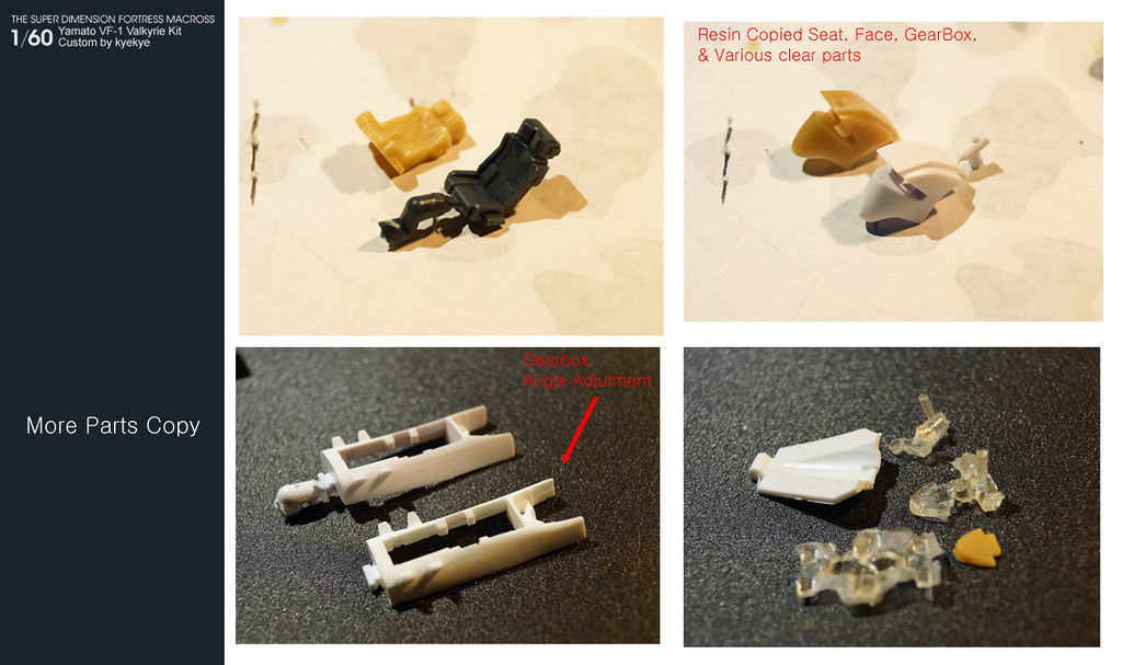
- I decided to go with Movie Hikaru version. so that means I need different pilot figure (one comes in kit is TV pilot). So I copied one from my other VF-1S, and made joints on 2 points (Ball joint on the head/neck, and pin on the wrists)
Also made some additional copies of parts I'm gonna modify/detail up
And started working on the canopy.
First, I made a resin copy of clear canopy, then cut out to make frame. Yamato kit has short monitor box and seat pushed forward, so I'll need to shorten/extend some parts. That will also give me some space for monitor LED work and space for seat detail! For the glass part, I don't have vacuum form set up, so I'll use heat press instead..


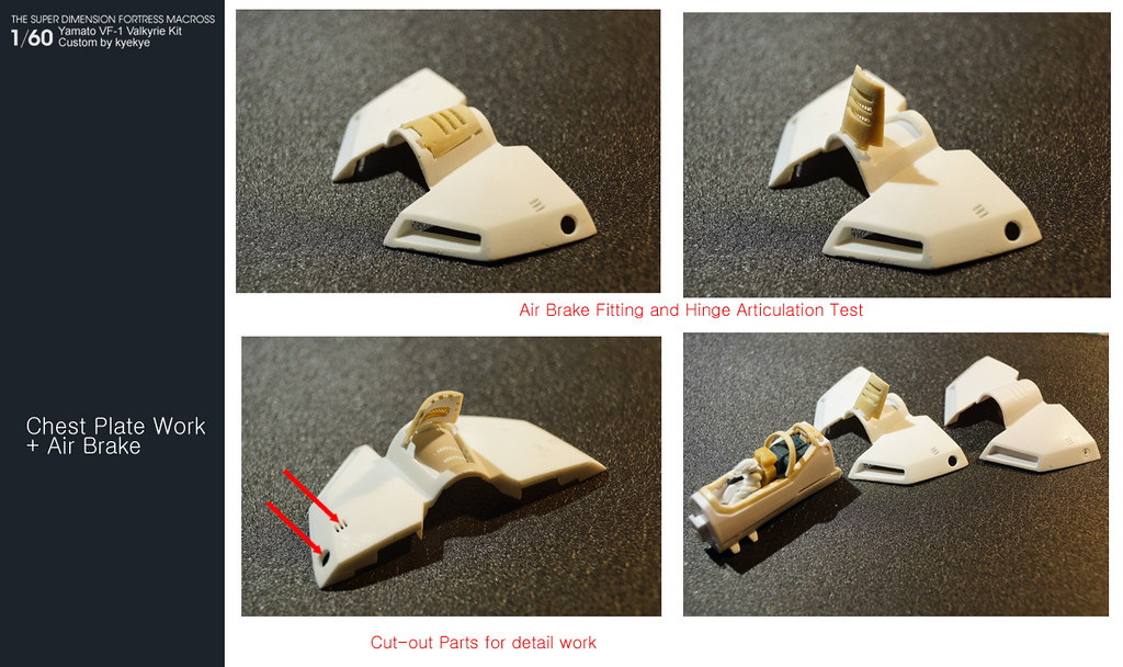
Back to the air-brake and chest plate. Added hinge for the air-brake. Adding piston actuator is impossible for the space.. so I gave up..
For the chest plate, I cut out some areas for detail up.
So far, it's going as I planned, but it's slow!!!
-
<geek mode>
0402 LEDs? For a simple way to dim LEDs, just increase the resistor value; the LED brightness is proportional (nonlinear, up to a point) to the current running through it. To find the resistor value, you can:
- look up the current/Lumens info on the LED data sheet & calculate the resistor value: R = (Vsupply - Vled_on) / current
- use a pot (resistor potentiometer), adjust to your desired brightness, & measure the pot resistance
- experiment by swapping in larger resistor values (binary search is effective)
Swap in the appropriate, cheap resistor once you have your value. It shouldn't make much of a difference but resistors typically have 5% or 10% value tolerances depending on what you choose; the tolerance may matter if your supply voltage is just above the LED turn-on voltage.
There are other, more-involved ways to electronically dim the LED but you can also use a regular LED instead of a super-bright, use a diffuser, paint over with transparent/translucent paint, or use gels.
</geek mode>
This is such a cool & inspiring project!!!
Oh boy.. you're trying to make me do Math!!!???
Seriously, Thanks for suggestion! I need to figure out how many LEDs will be attached to how many batteries/switches before do the math thou.
Jaw dropping awesome!!!!!!!
Thanks!
I'm speechless. I'd love to see you detail up one of those 1/24 scale Valks......
I'm running out of space in my mancave! anything bigger than 1/60 would be troublesome..
You got it. Recaster is actually closer to you than I am.
Thanks >EXO<! Maybe I can have him ship the set directly to me and save some shipping cost?
-
First one is 30th anniversary vf-1j with additional gimmicks.
They will milk it out while working on the new 19!!!
-
First, Thanks for nice comments! not much progress (to make post) last weekend, so I'll update more this weekend.
awesome work! hat off!
Just wonder 2 issues, 1st where to order those hands replacement? HLJ? 2nd, the LED shown on the wings, is that a real LED bulb or you are using optic fiber? I saw many projects are using fiber optics, because it saves spaces.
1. 1/100 Mechanical Hand 100 Square G Gray by Hobby Base or 1/100 Mechanical Hand 100 Round G Gray
2. Those are just wiring test LEDs. Fiber Optic cable doesn't seem bright enough while LED seems too bright.. I'll figure out something this weekend.
The actual LED I plan to use is 1/4 of that size. -
I'm with you. Really...never a big fan of those super pack parts anyways...I'm fine with the v1.0....I really am.

Bandai 1/72 fully transform able VF-1 plastic kit for Macross 30th Ann
in Model kits
Posted
One thing I noticed is the head laser on S.
The angle on fighter mode looks parallel, but angle on Battroid looks spread apart. Does that mean they have some kind of joint/hinge on the root of that tiny head laser??