wm cheng Posted March 29, 2004 Author Share Posted March 29, 2004 Another good area to check, since its so flat, any imperfections will show up easily. Quote Link to comment Share on other sites More sharing options...
wm cheng Posted March 29, 2004 Author Share Posted March 29, 2004 You see, when you're done, there's really very little visible left of the Mr. Surfacer - noticed the panel lines re-scribed through the seam (that's with the photo-etched saws from Hasegawa mentioned earlier) Quote Link to comment Share on other sites More sharing options...
wm cheng Posted March 29, 2004 Author Share Posted March 29, 2004 But if you see any of the fine lines filled in with the grey of the Mr. Surfacer, it means that it did its work!! Quote Link to comment Share on other sites More sharing options...
wm cheng Posted March 29, 2004 Author Share Posted March 29, 2004 I also sanded the wing edges, since its molded this way (top and bottom one piece - except for that stupid insert), there will be a separation seam in the mold process that we need to get rid off. Additionally, we need to continue the panel lines around the leading edges to join up with the panels on the underside. Luckily Hasegawa was dead on in lining them up. Quote Link to comment Share on other sites More sharing options...
wm cheng Posted March 29, 2004 Author Share Posted March 29, 2004 Well, here are those rare earth magnets. I got them from Lee Valley Tools here in Toronto - as you can see they come in various tiny sizes to choose from. Here's is their site, they deliver right to your door. http://www.leevalley.com/wood/page.asp?pag...ID=&ccurrency=1 http://www.leevalley.com/wood/page.asp?pag...currency=1&SID= I ended up using the middle ones I think they were 3/8" but its always good to get a few varieties. I glued in all the pieces that connect/bridge the two leg halves to make sure that the magnet would clear any plastic. I decided to be lazy and use a metal washer for the fast pack side. These little magnets are so strong, I don't think I need two magnets, one on either side. I will just put the magnet inside the leg and attached the washer to the inside of the fast-packs. I wasn't really planning on detailing the inside of them anyhow, so I will just surface mount them. Quote Link to comment Share on other sites More sharing options...
wm cheng Posted March 29, 2004 Author Share Posted March 29, 2004 Here's a dry run to get the approximate location on the fast packs. You could put two in to be more secure, but I only chose one. Luckily, the insides of the packs never touch the surface of the legs, only the perimeter of the packs are touching the legs, so there is no need to counter sink the metal washer. Additionally, this also prevents the surface of the leg from marring (I was afraid of this before I began). To make sure the metal is no way near the actual surface of the leg, I also very slightly bent it with a pair of pliers so that it more closely resembles in inside curvature of the fast packs. Quote Link to comment Share on other sites More sharing options...
wm cheng Posted March 29, 2004 Author Share Posted March 29, 2004 Here's the 5-min epoxy "goop" I laid in. Inside the leg can be messy, it just has to prevent the magnet from falling around. You should be neater on the packs, since we don't want the epoxy to be scratching our finish off our legs when we are done. When I test fit them, the washers are actually always at least 1/8" from the surface of the plastic, plus the thickness of the plastic, its magnetic field was strong enough to get pass 1/4"! Two might be more secure if you are zooming it around, but for me, I think one will surfice for my needs. Quote Link to comment Share on other sites More sharing options...
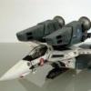
wm cheng Posted March 29, 2004 Author Share Posted March 29, 2004 I glued the two halves together, here you see the pack on - the magnets work really well. Quote Link to comment Share on other sites More sharing options...
wm cheng Posted March 29, 2004 Author Share Posted March 29, 2004 More sanding - one finished, one just begun... sigh... sanding sanding sanding I'll sign off for now. Quote Link to comment Share on other sites More sharing options...
Myersjessee Posted March 30, 2004 Share Posted March 30, 2004 great idea with the magnets!!! Ill be stealing that one! Quote Link to comment Share on other sites More sharing options...
Angel's Fury Posted March 30, 2004 Share Posted March 30, 2004 Thaks for the latest updates wm cheng! It's been a while since the last update. Quote Link to comment Share on other sites More sharing options...
Dragon Lord Posted March 31, 2004 Share Posted March 31, 2004 Using the magnets is a great idea! Looking really good. Joe P. Quote Link to comment Share on other sites More sharing options...
Nani?! Posted March 31, 2004 Share Posted March 31, 2004 Man, all these cool techniques and craftmanship.... truly you are the master WM Cheng. Look forward to the finished peice~! Quote Link to comment Share on other sites More sharing options...
David Hingtgen Posted April 1, 2004 Share Posted April 1, 2004 You know I just realized (embarrassingly for me) that the engine (both front and rear ends) looks quite TF-30-ish. As in, the Tomcat's original engine. (Though my FIRST impulse was J79-ish, most famously used in the F-4) "When all else fails, make a Valk use F-14 parts". Quote Link to comment Share on other sites More sharing options...
wm cheng Posted April 3, 2004 Author Share Posted April 3, 2004 Ok, a few more hours - just sanding. Here's a tough spot, I scraped away at the plastic to get both sides level (inside the intakes - lower lip) and I will fill it with Tamiya Putty - its a bit more of a gap than Mr. Surfacer can handle. Quote Link to comment Share on other sites More sharing options...
wm cheng Posted April 3, 2004 Author Share Posted April 3, 2004 The leg halves didn't go together quite as smoothly - there was a bit of hieght difference between the two halves. I think its my fault for not properly aligning them while the glue was still setting. But since this is a major seam and highly visible, I am going to use Tamiya Putty to build up both sides to match exactly while filling the seam. Additionally it will eliminate that wierd scribed panel lines which don't meet at the bottom surface of the intakes (on the outside) and allow me a blank slate to rescribe that line in afterwards. Quote Link to comment Share on other sites More sharing options...
wm cheng Posted April 3, 2004 Author Share Posted April 3, 2004 Remember to scribe back any lines lost due to sanding... Quote Link to comment Share on other sites More sharing options...
wm cheng Posted April 3, 2004 Author Share Posted April 3, 2004 I added this scribed line in since it should look like the arm can separate from the shoulder piece - and made it quite deep. Quote Link to comment Share on other sites More sharing options...
wm cheng Posted April 3, 2004 Author Share Posted April 3, 2004 You can see a sink hole (actually on a little depression) towards the top above the seam you see a little round smudge of Mr. Surfacer, doing its job filling it out. Funny I haven't really come across sink holes on Hasegawa kits before... Quote Link to comment Share on other sites More sharing options...
wm cheng Posted April 3, 2004 Author Share Posted April 3, 2004 Here are another two below the seam that should be filled in - however, when the arm is in place, it will mostly be obscured by the back pack anyways. So its not as vital to fill these as the ones on the shoulders - but hey depends on your mood on sanding (I'm still debating on wether to fill the injection pin holes in the landing gear doors - that's how lazy I am these days!) Quote Link to comment Share on other sites More sharing options...
wm cheng Posted April 3, 2004 Author Share Posted April 3, 2004 Here's a shot of a pin vise - you can get these at most local hardware stores for cheap. They usually come with a small assortment of tiny bits stored in the shaft. I like these since they are hand-powered and can be extremely precise and careful with them. You should hold them in your thumb and index finger with your "peter-pointer" finger on the top of the shaft - and just roll your thumb to twist the shaft allowing your "peter-pointer" finger on top to apply the downward pressure. But let most of the bit do the work since the plastic is extremely soft. In the background I got a case of smaller drill bits of varing sizes - this is just the cheap one (made in China) for around $10cdn. The very fine bits can snap quite easily if you're not careful and allow it to bend - but for $10 for such a variety pack - they are almost disposeable. Let me know if any of you have had better luck with the expensive ones not breaking (I would guess you get what you paid for - but that's not always the case ) Quote Link to comment Share on other sites More sharing options...
wm cheng Posted April 3, 2004 Author Share Posted April 3, 2004 I am using the pin vise to drill out the depressions that Hasegawa tried to make in the side of the afterburning cans. Its really easy since they already marked them - just not deep enough. The hardest part is not going through the plastic and creating a hole. Quote Link to comment Share on other sites More sharing options...
wm cheng Posted April 3, 2004 Author Share Posted April 3, 2004 Here's a shot when they are done. I did them before sanding the edges and the sprue attachment points since I didn't want to accidentaly sand away the very faint depressions away marking where I should drill. Quote Link to comment Share on other sites More sharing options...
wm cheng Posted April 3, 2004 Author Share Posted April 3, 2004 These are the little styrene strips that you can buy at most model train stores - I'm too lazy to cut even strips from a sheet of styrene so I bought the ones already cut . Isn't civilization great I plan on gluing these to the insides of the nozzles to create that ribbed look. I'm sure Hasegawa will come out with a photo-etched part for this shortly after we make these ourselves But until then... Hopefully there will be more tomorrow. Quote Link to comment Share on other sites More sharing options...
David Hingtgen Posted April 3, 2004 Share Posted April 3, 2004 That's the exact (and I mean EXACT) same set of drill bits I have. Of course over the years, only about half of them are the "originals", many replacements (especially in the 70+ ones). Never found replacements to last longer, even if they do cost a lot more per piece. From what I've heard, many hobby drill bits are actually used ones from PC-board making places--after they get too worn/short to get through a stack of chips/boards, the tip is re-pointed and the remaining bit is sold to us, since we generally only need it to go a little ways--which is why the actual bit part is so short on most of the ones you see. Anyways---while I do have pin-vise, I *much* prefer my mini spiral drill. Smaller, lighter, and you can also use it like a pin-vise, in addition to the spiral mechanism. They're worth their weight in gold. Ah yes, Evergreen styrene. .100x.020 is my fave. (Despite having HO scale trains, I have no HO scale styrene--I use it for filling, never scratchbuilding HO houses and the like) Nothing like an AMT/Ertl kit to use up your supply of gap-filling styrene strips! Quote Link to comment Share on other sites More sharing options...
onezero Posted April 4, 2004 Share Posted April 4, 2004 Nothing like an AMT/Ertl kit to use up your supply of gap-filling styrene strips! Or gap-filling superglue, or gap-filling epoxy putty .... Quote Link to comment Share on other sites More sharing options...
David Hingtgen Posted April 4, 2004 Share Posted April 4, 2004 (edited) They didn't make "Grand Canyon"-filling superglue, so I just used like 1.5 bottles of gap-filling on my 1701-B kit combined with many .020 (and .100) strips... (the only thing with worse fit than their Excelsior, is their modified Excelsior...) Edited April 4, 2004 by David Hingtgen Quote Link to comment Share on other sites More sharing options...
onezero Posted April 4, 2004 Share Posted April 4, 2004 You haven't tried making the cut-away Enterprise whole, have you? Quote Link to comment Share on other sites More sharing options...
FlyingPika Posted April 4, 2004 Share Posted April 4, 2004 thxns once again cheng for another great how to, i was just wondering, what is that razor saw u used for scribing the lines again? I got an etching saw but its way to thin. Which one are you using? thanks Quote Link to comment Share on other sites More sharing options...
Terpfen Posted April 4, 2004 Share Posted April 4, 2004 thxns once again cheng for another great how to, i was just wondering, what is that razor saw u used for scribing the lines again?I got an etching saw but its way to thin. Which one are you using? thanks Here. Quote Link to comment Share on other sites More sharing options...
Stamen0083 Posted April 4, 2004 Share Posted April 4, 2004 (edited) I got an etching saw but its way to[sic] thin. It's supposed to be thin. Thick saws defeat the purpose. These saws scribe panel lines that are the perfect Hasegawa width. They're not for cutting through plastic, but they CAN be used to do so, if you're careful. Edited April 4, 2004 by Stamen0083 Quote Link to comment Share on other sites More sharing options...
wm cheng Posted April 5, 2004 Author Share Posted April 5, 2004 A few more hours today - just a ton of sanding and re-sanding. David, man, those AMT/Ertl Star Trek kits sure bring back nightmares!! They must be one of the worst kits in history - did you ever build the "Airwolf" kit of the Bell 222 by AMT/Ertl - just about made me swore off models all together! Its easier to leave the styrene strips long so you can hold on to them while you're gluing them in place. Then snip them a tad long (we'll sand them down later) I've decided to only do the strips to the top and bottom. Quote Link to comment Share on other sites More sharing options...
wm cheng Posted April 5, 2004 Author Share Posted April 5, 2004 I've trimmed them down a bit after the glue had dried. Quote Link to comment Share on other sites More sharing options...
wm cheng Posted April 5, 2004 Author Share Posted April 5, 2004 On wet coarse (100grit) sanding film, I dragged the tail cone with the slightly long strips along the surface. I always drag in one direction (right to left - in this picture) so that the strips will always be pressed against the tailcone - I didn't drag against the glue (you don't want to accidentally pull the strips away from the tailcone) Quote Link to comment Share on other sites More sharing options...
wm cheng Posted April 5, 2004 Author Share Posted April 5, 2004 The edges should be flush with the ends of the tailcone and look molded in instead of added on - I thought it worked out pretty well. Quote Link to comment Share on other sites More sharing options...
Recommended Posts
Join the conversation
You can post now and register later. If you have an account, sign in now to post with your account.