

captain america
-
Posts
3465 -
Joined
-
Last visited
Content Type
Profiles
Forums
Events
Gallery
Posts posted by captain america
-
-
On 7/19/2022 at 2:56 AM, ChristopherB said:
"Pic 42: the burner cans are also done, though these still feature a seam. I’m debating whether it’s best to leave these smooth and let the builder fill them, or try to mask the seam with ribbing of some sort. As much as I would have preferred a seamless unit, the complex shaping of the part made this impossible."
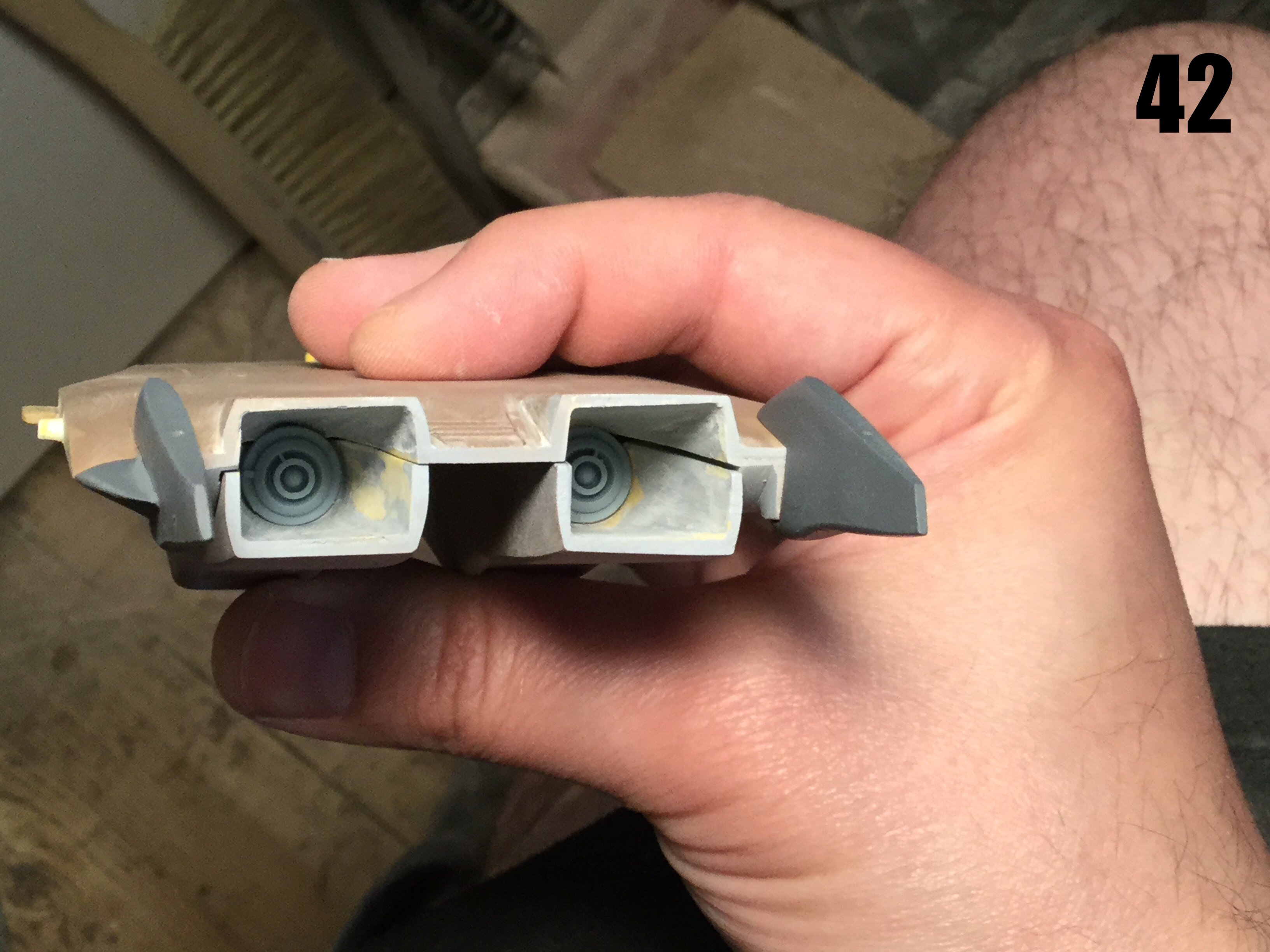
As beautiful as your Dragon II is, that gap/seam always bothered me a bit, and I know you mentioned not having a choice. Plus I'm not too sure how visible it will be to begin with especially with the nozzles there. Likewise it can be filled with putty and so forth. But looking at the most recent pictures you posted of the final version, there's only one that really shows that area from the right angle although it's hard to see thanks to the dark gray primer and lighting.

The gap is still quite large in this picture, but that's mostly because the upper/lower sections haven't been glued/compressed together. As such, I was wondering what's your feedback on how good/bad the seam will be in the production version. Did you decide whether to leave the seam smooth or camouflage the seam with ribbing?
I went with smooth, simply because if I add detail to the burner can, it will only make it harder to fill that seam afterward. The way I designed it, you can putty & sand the burner, and then drop the flame ring in at the end so that it doesn't get damaged. Because of the zozzle design, the cans are quite well shrouded from most viewing angles. The ejector pin mark on the nose wheels is my bad: I should've filled them, but I forgot.
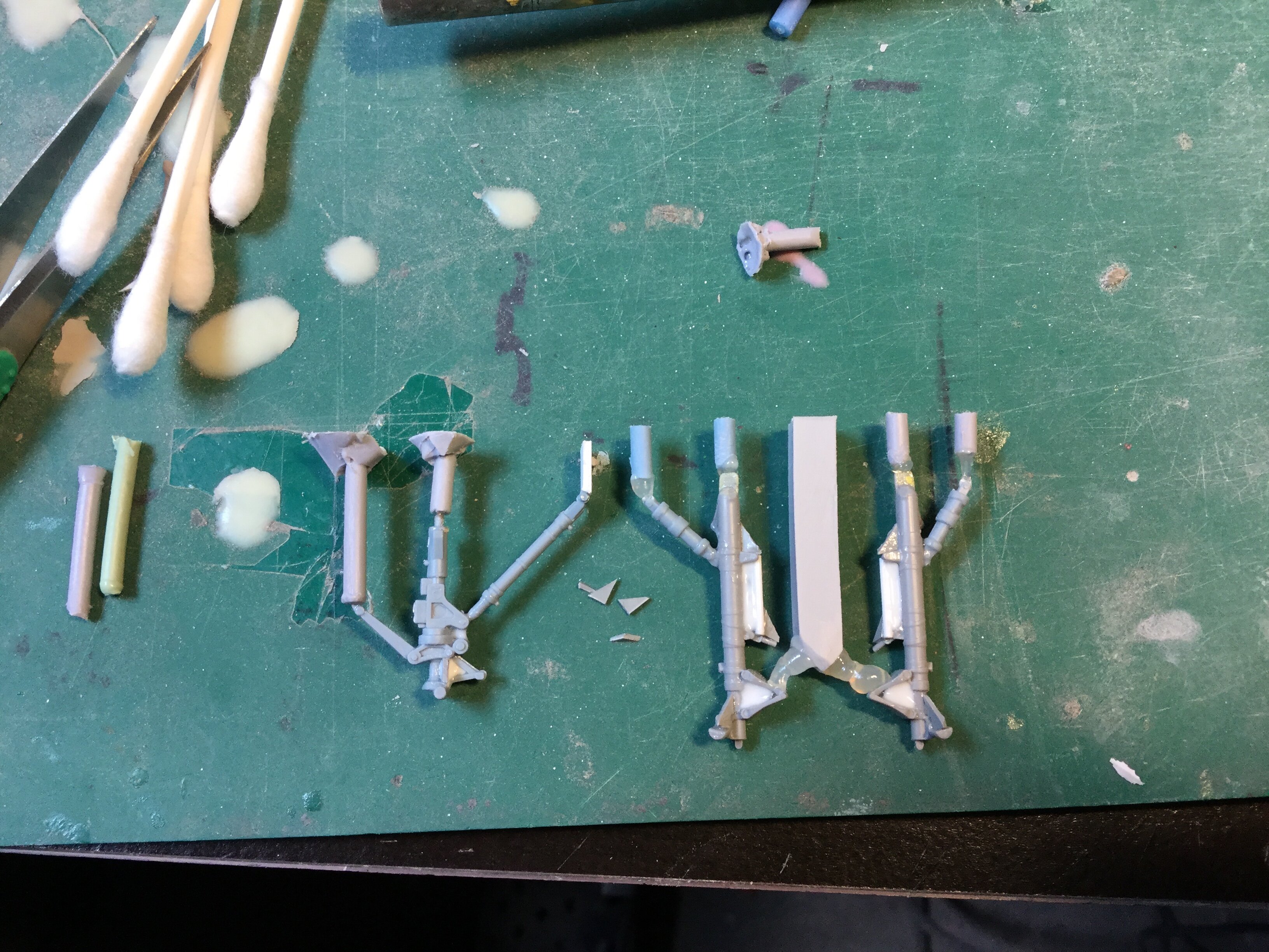
More good news is that the landing gear struts all came out beautiful The main gears probably didn't need a metal insert, but I added one anyway just to be safe. At some point, we may need a 2-seat attack variant of this thing.
)")
-
Captain's Log: Monday, July 18th, 2022.
Molding is going well! The bulk of the masters have now been molded, but because everything is either slow or delayed these days, I'm waiting on the materials I need to finish the remainder of the molds, so the frustration continues. As such, I'll use this time to try to mold as many of the very delicate parts as I can and get those out of the way.
-
On 7/8/2022 at 5:57 PM, sbantonelli said:
You have a great knack for interpreting anime and turning it into reality. Thank you for all of the incredible kits over the years.
Thank you, you're most welcome. Truly I have been humbled over the years by the faith people have had to fund my projects, sight unseen, believing that they would meet expectations. I can't express how much I appreciate everyone who has helped to make projects like these a reality, because the truth is, I couldn't have done it without your help.
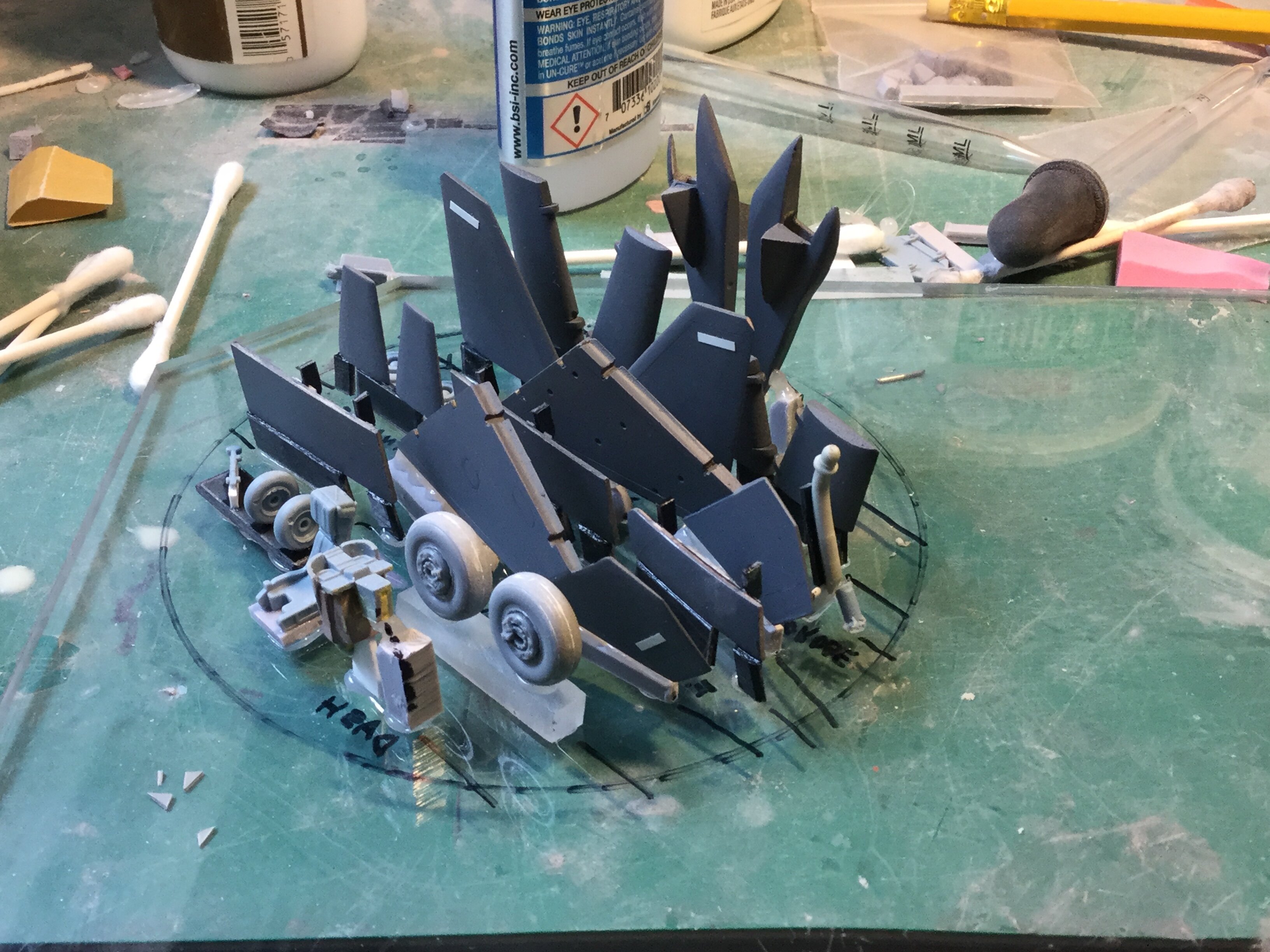
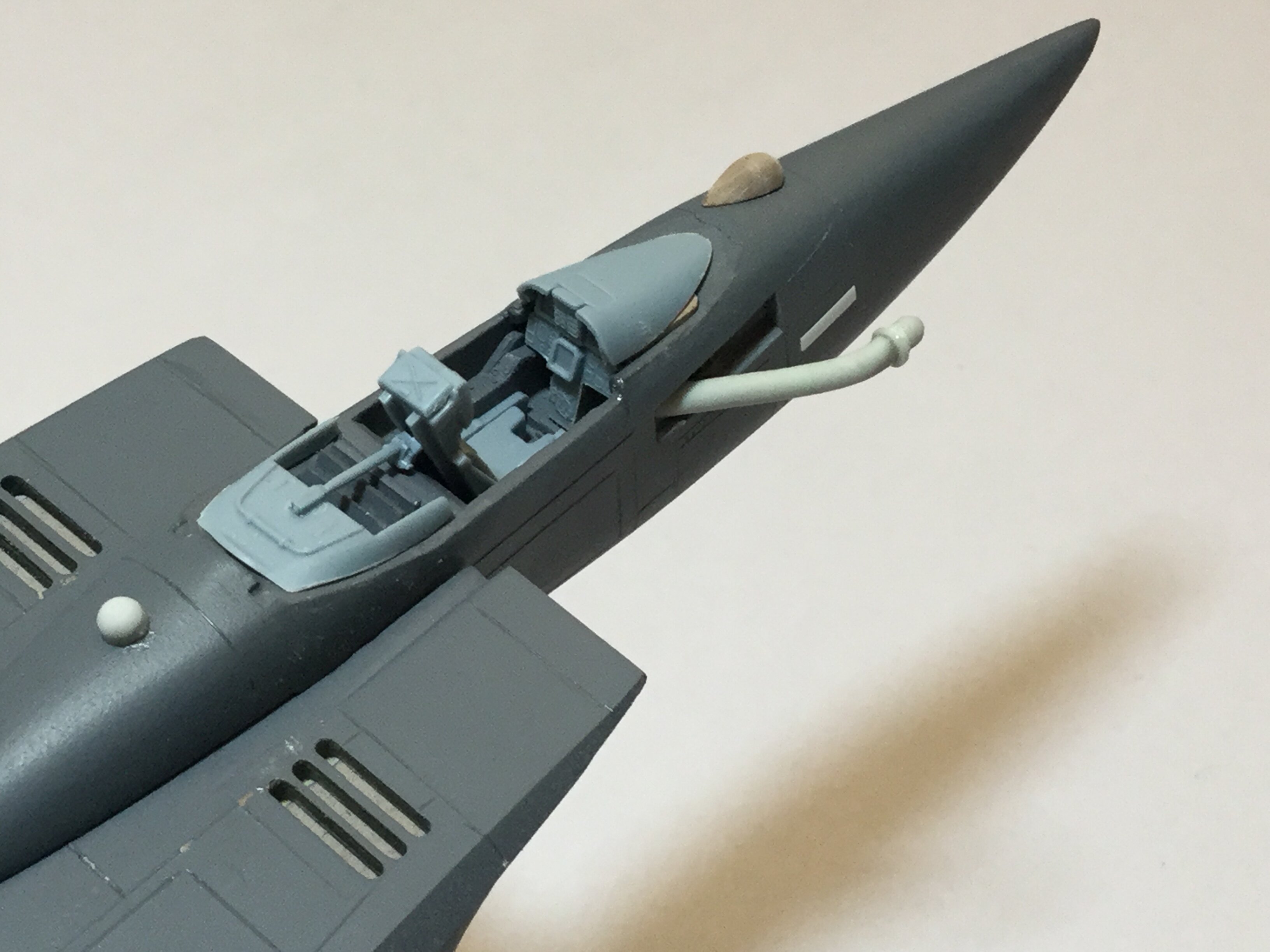
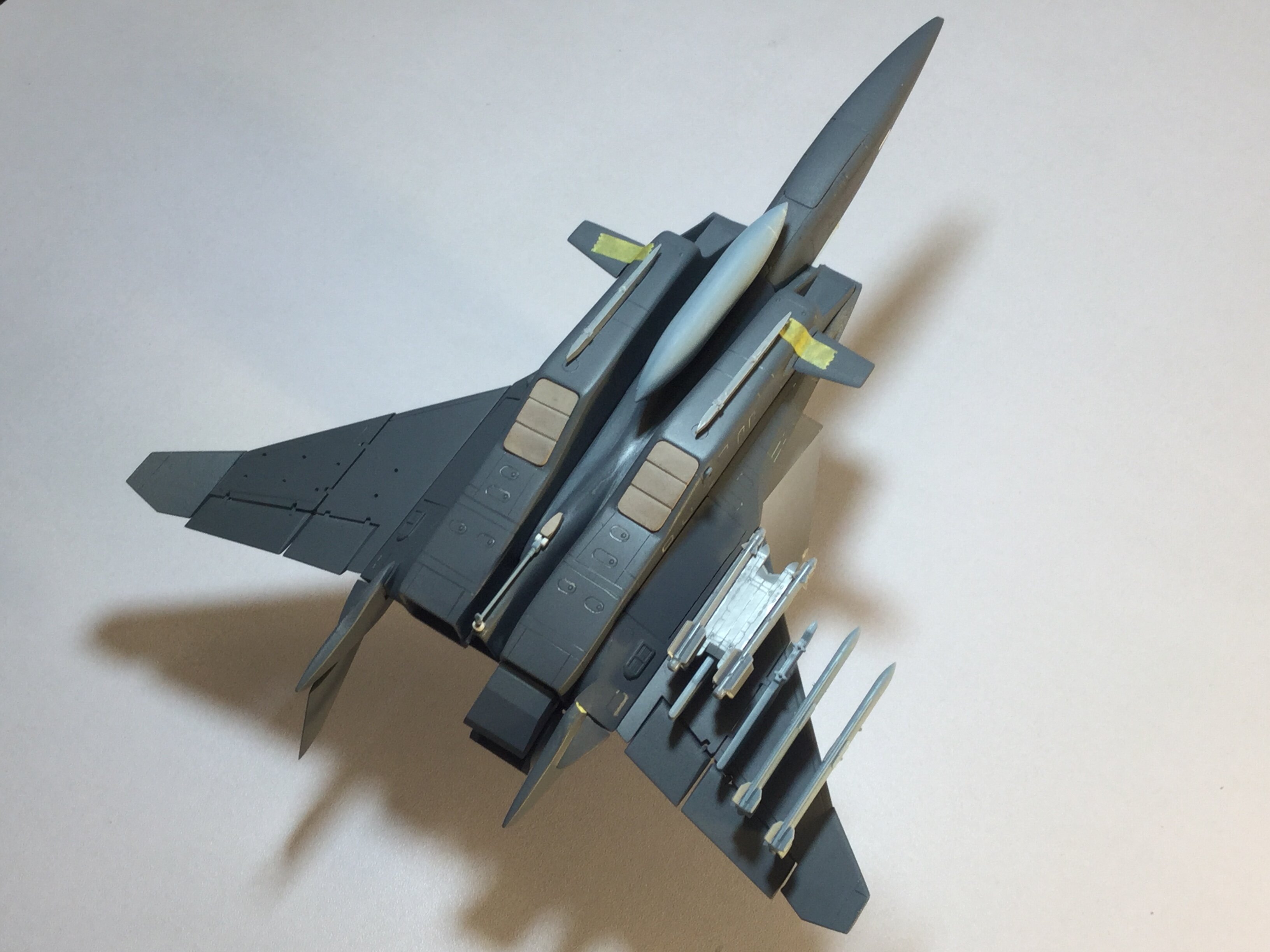
Here are some final pics before I commit the masters to mold-prep. Please excuse the floppy gear bay doors, which are held with Tamiya tape: once I add the hinges, the only way to build the doors closed will be to trim those hinges off, just like your average Hasegawa kit. Some very fine detail parts are going to be extremely challenging to mold, so please pray that everything goes smoothly! One pleasant surprise is that the Dragunn doesn't do a wheelie on its tailpipes, even with all the weight shifted aft. The main struts will have brass inserts for added strength, and a few small details were omitted from the pics to avoid losing or damaging them, like the teeny-tiny control stick and the door for the refuelling probe. The canopy will be clear, of course, and the casting for those is already underway.
-
It.
Is.
Finished!
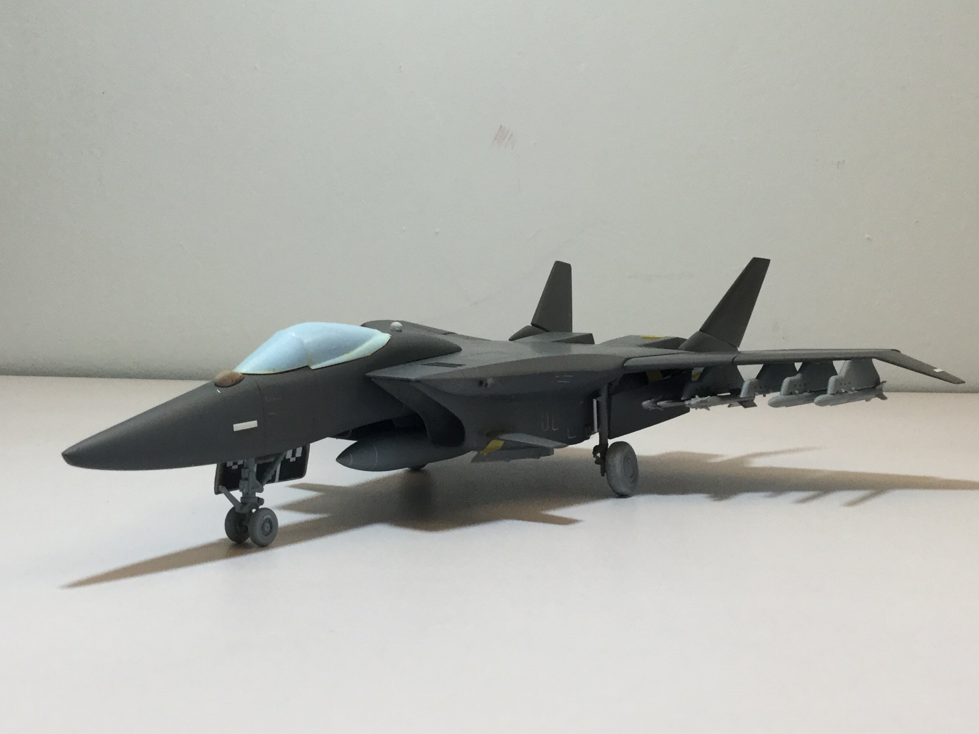
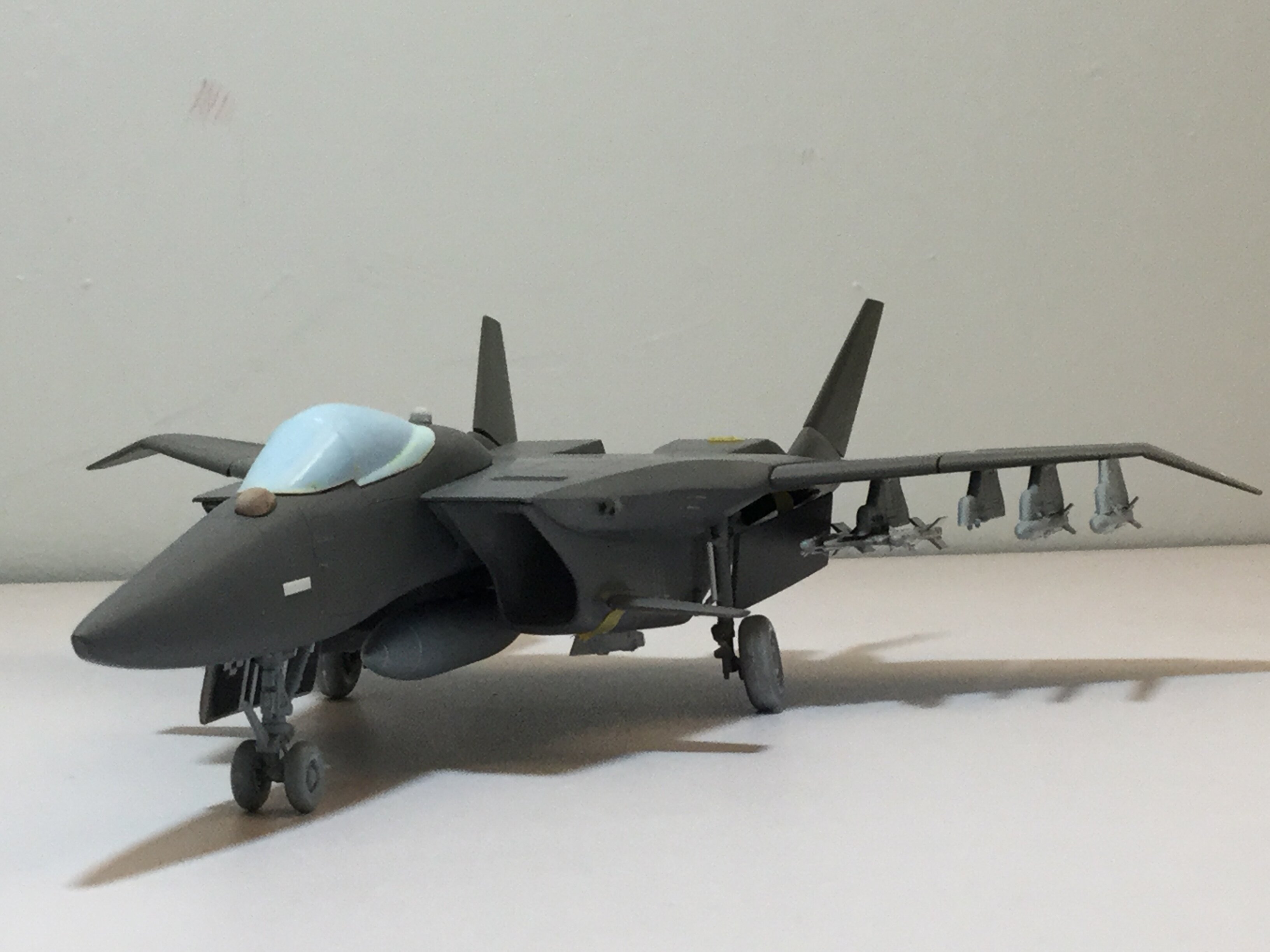
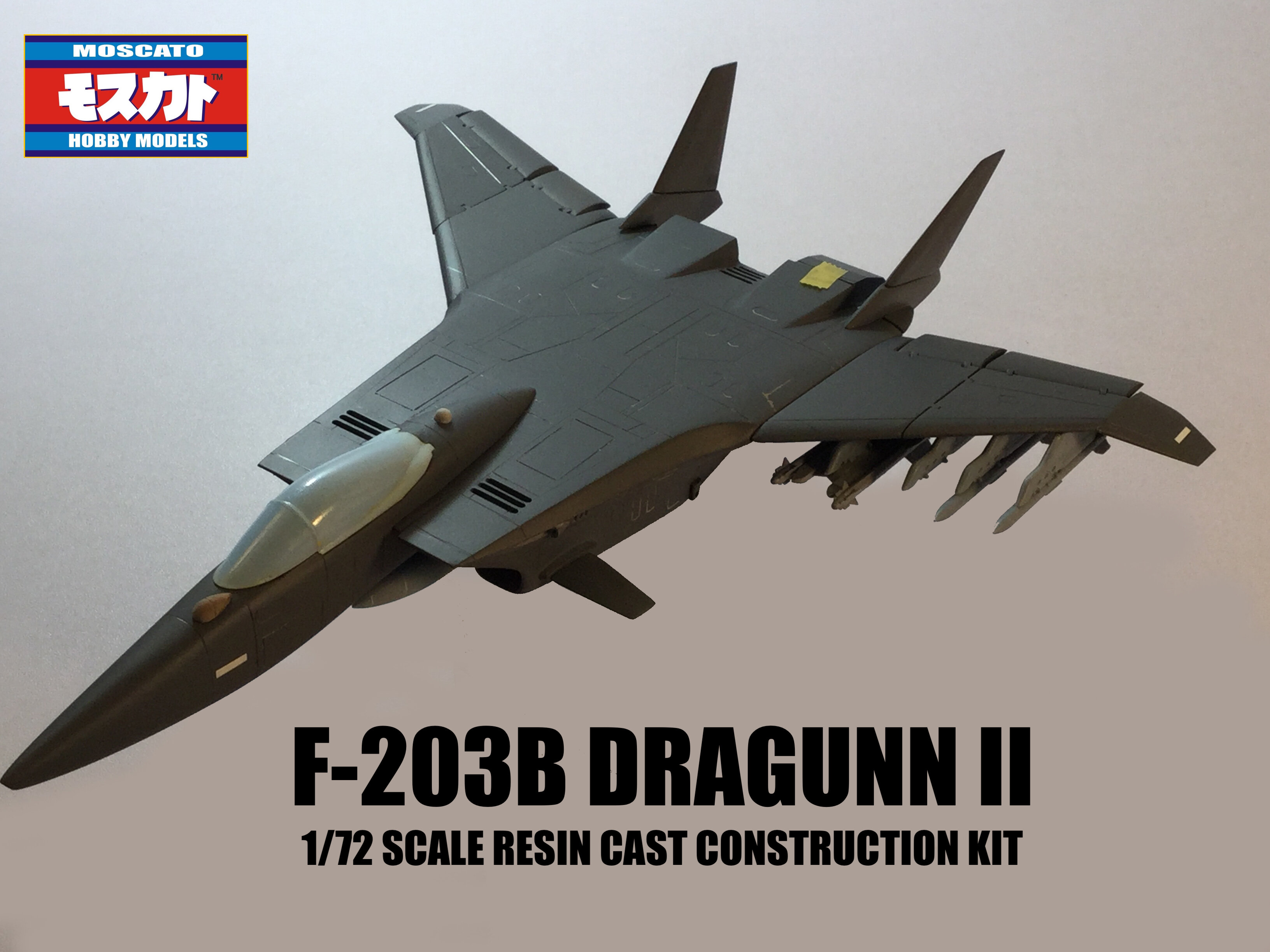
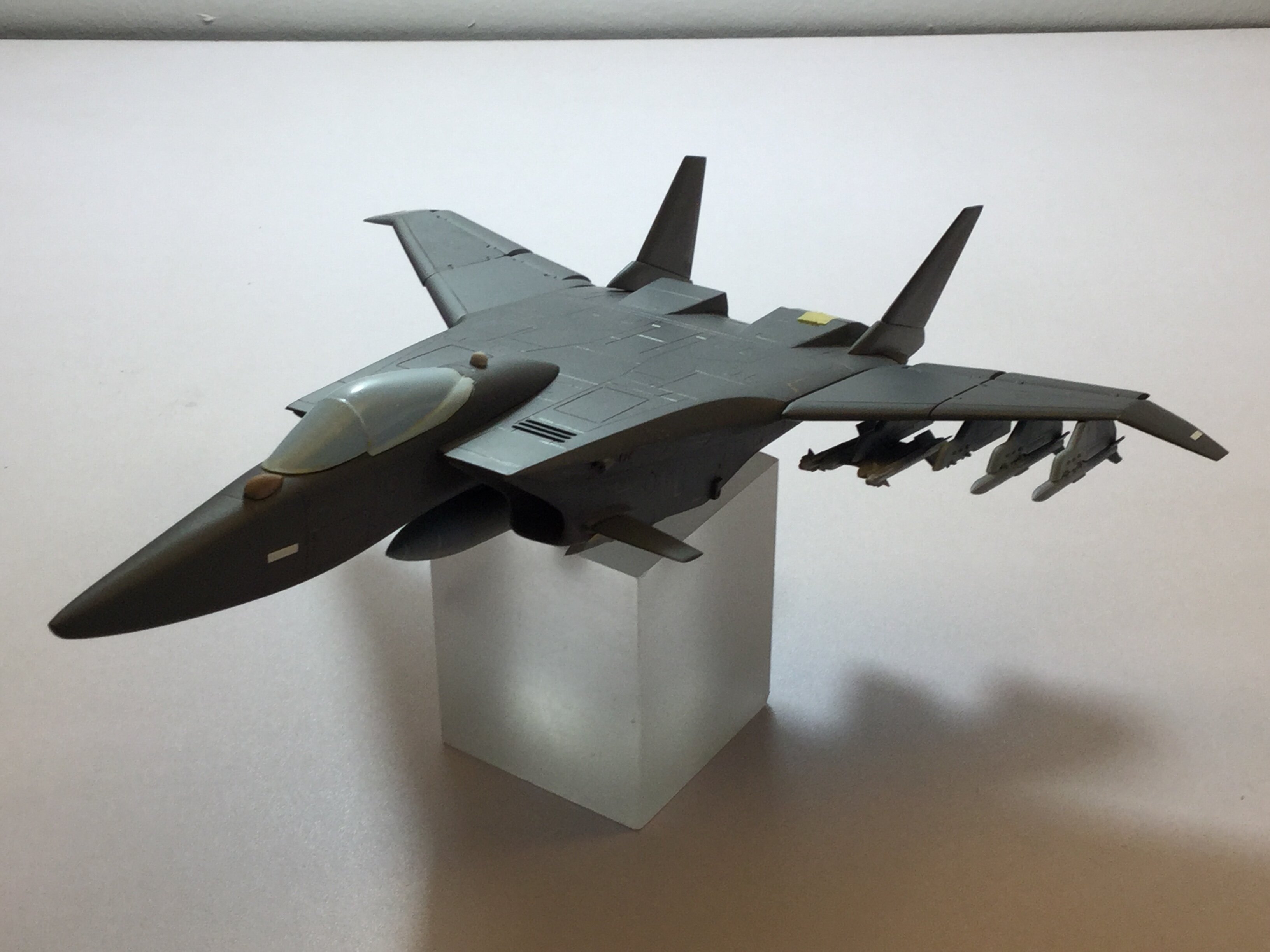
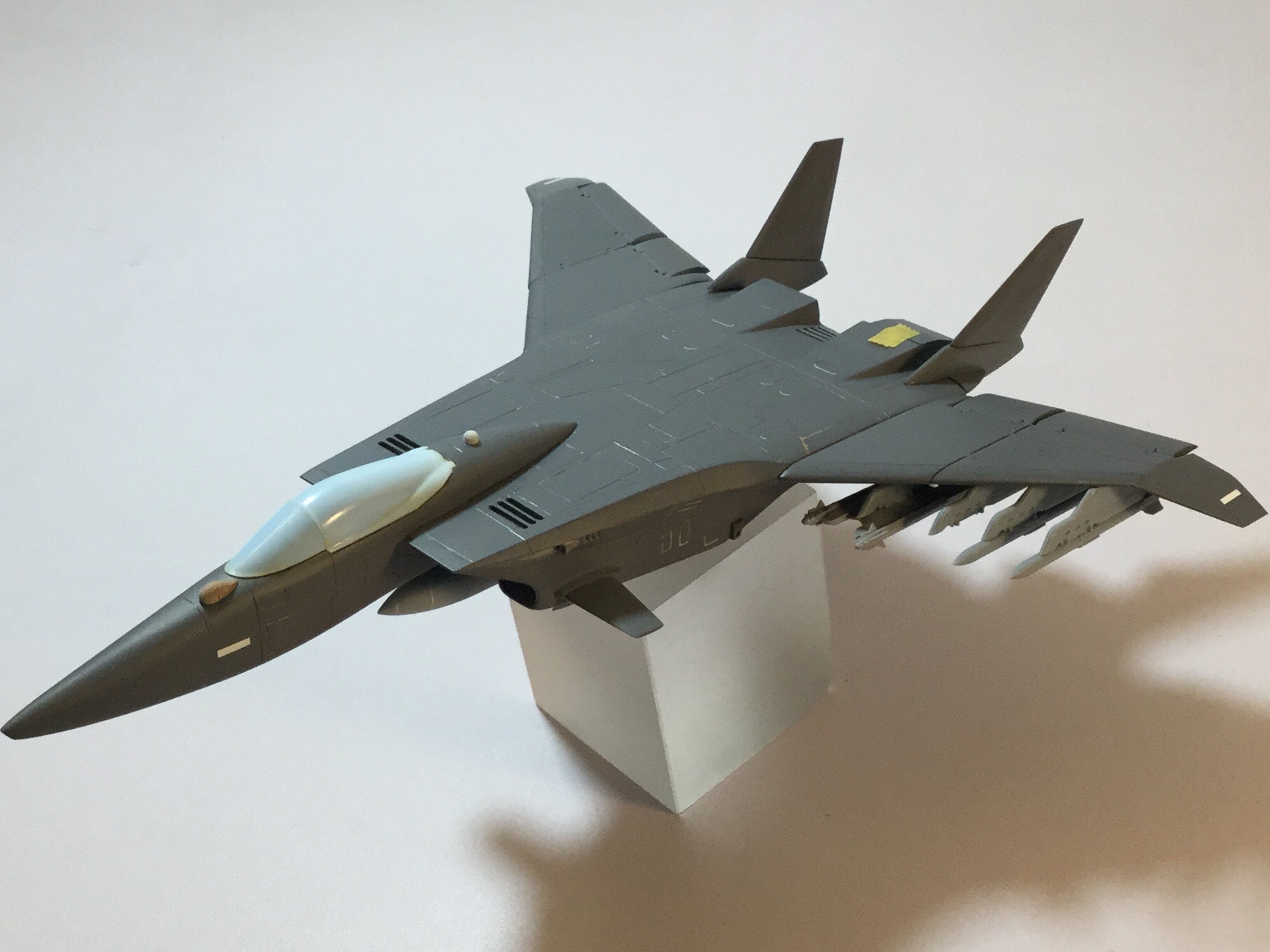
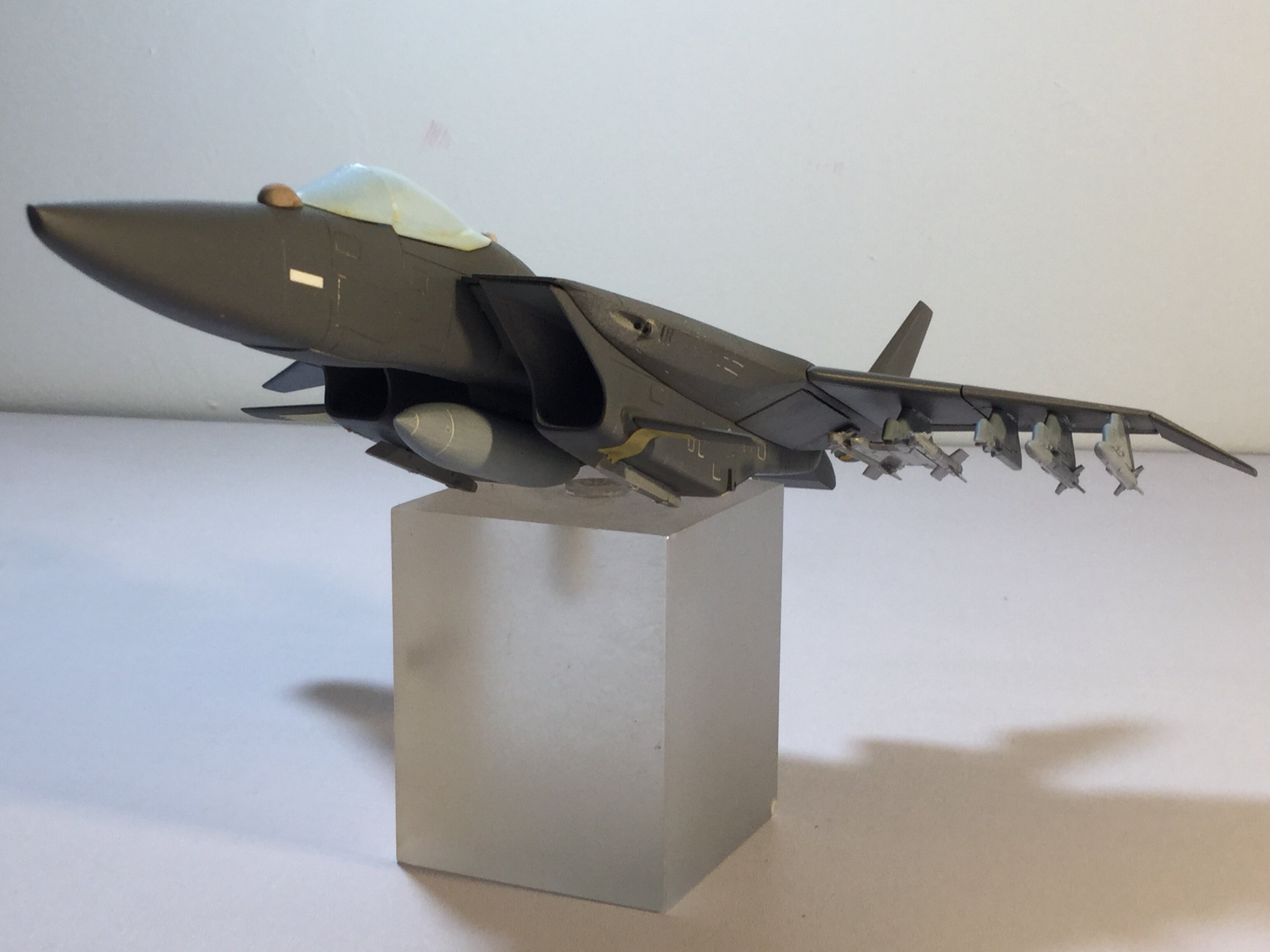
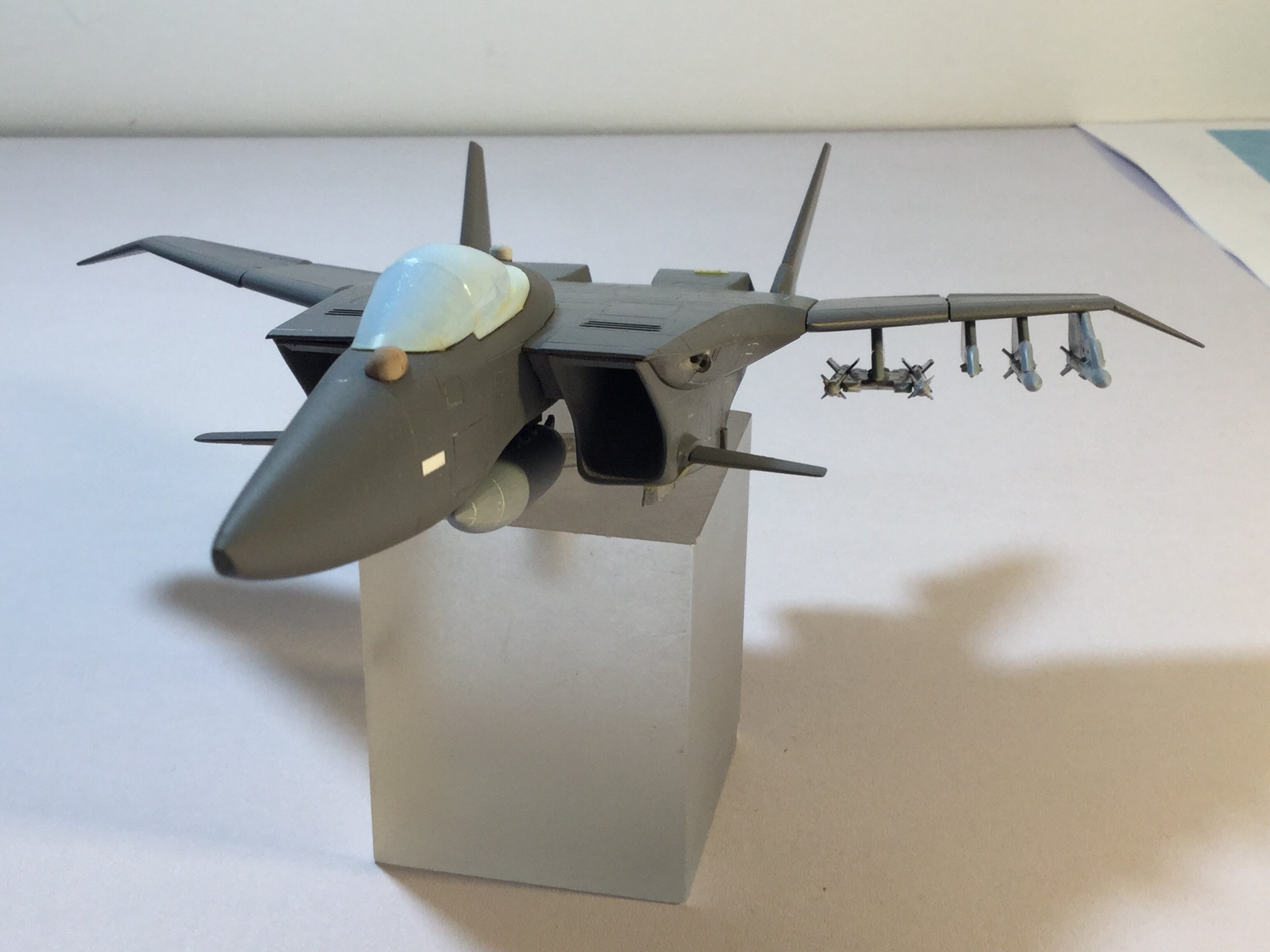
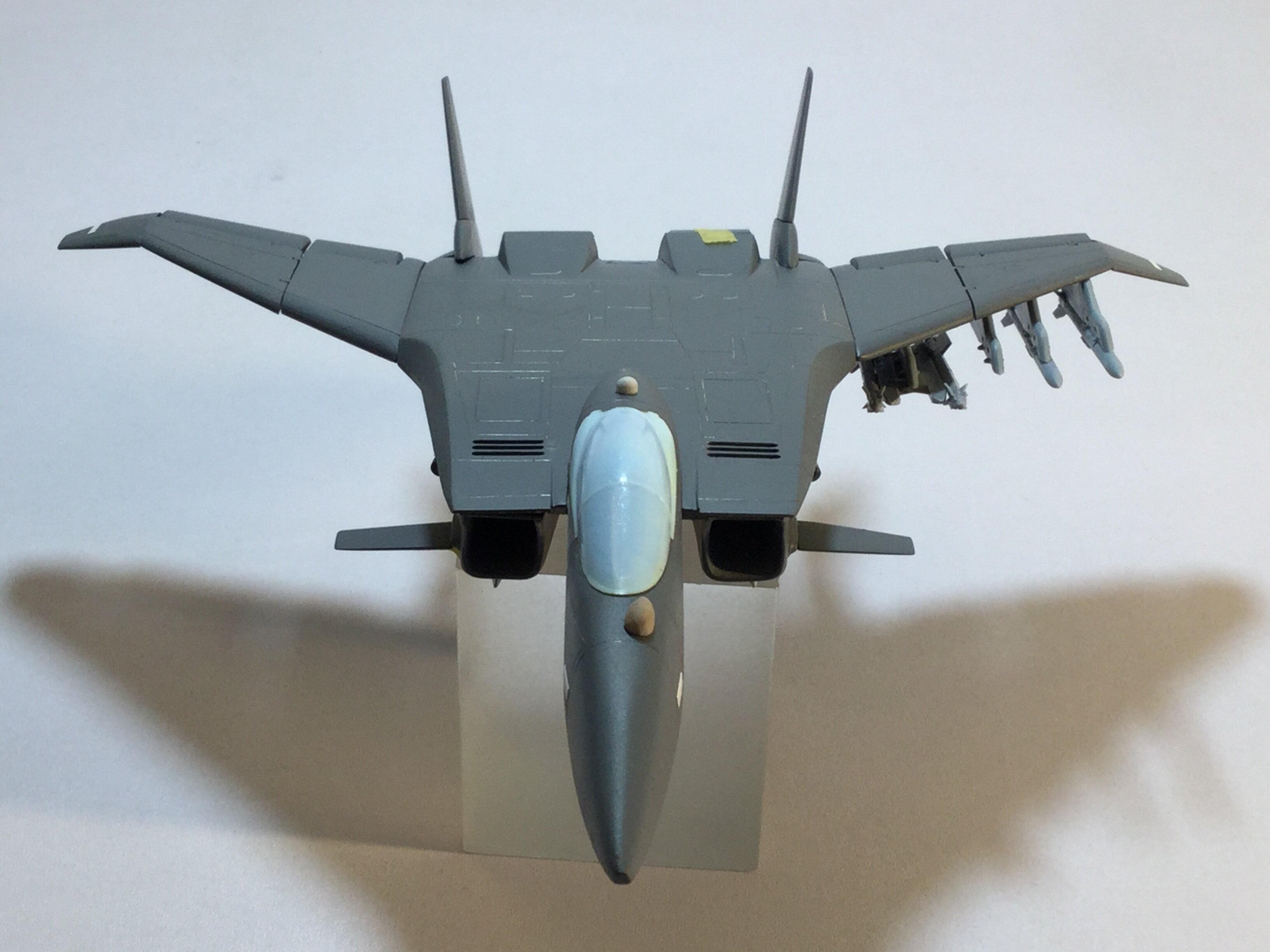
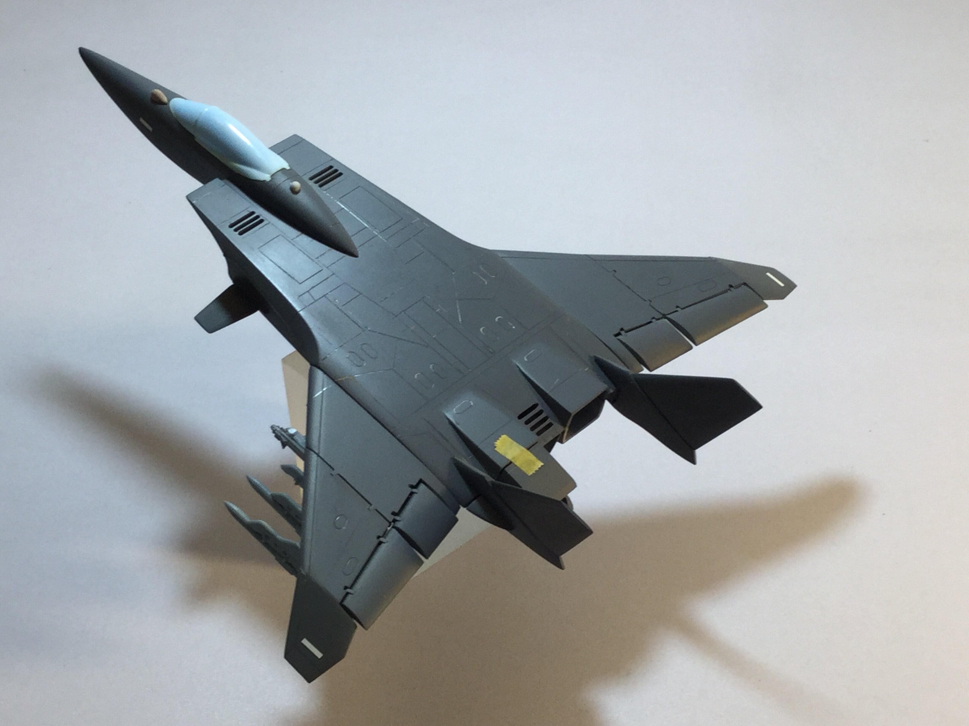
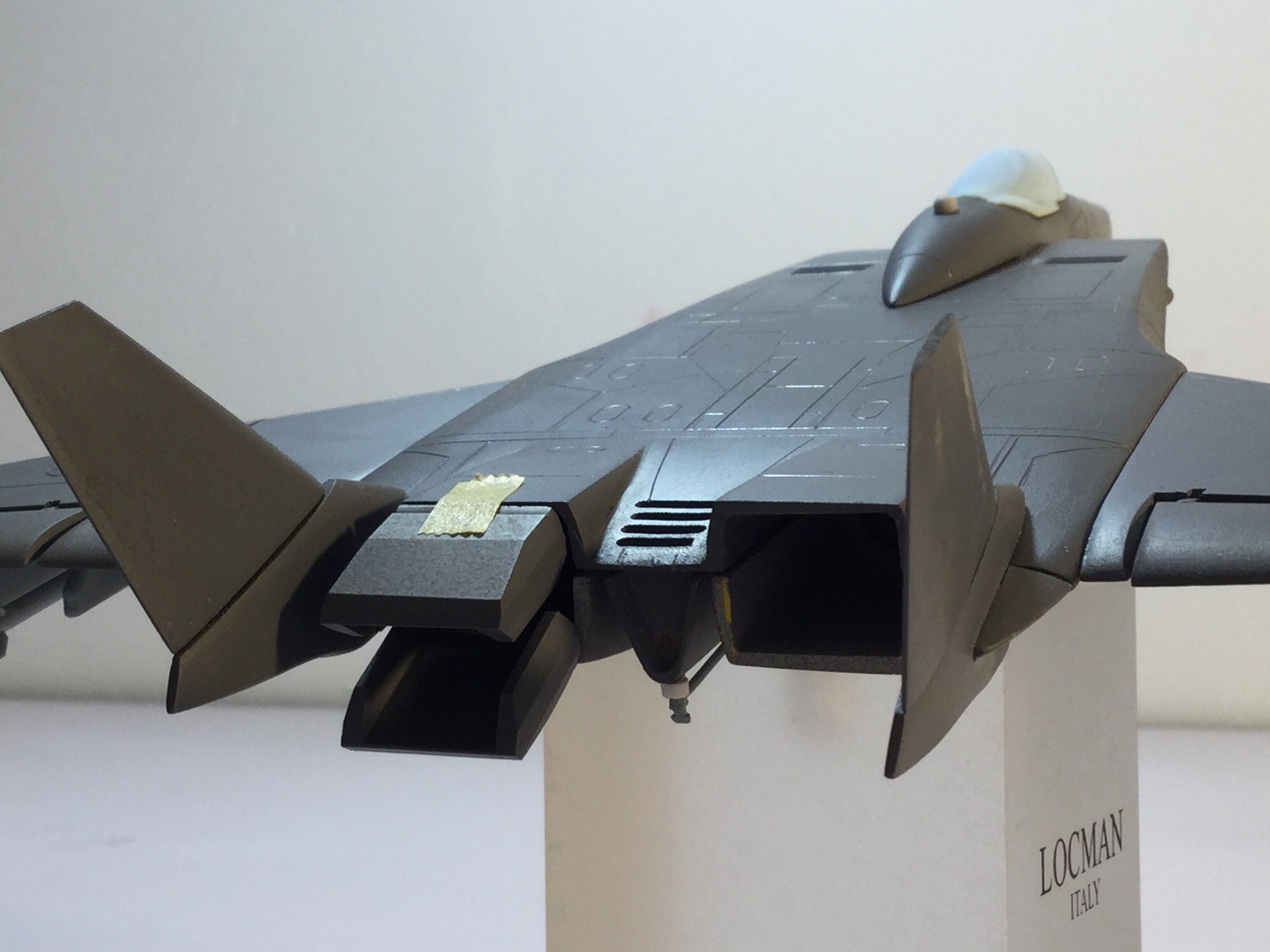
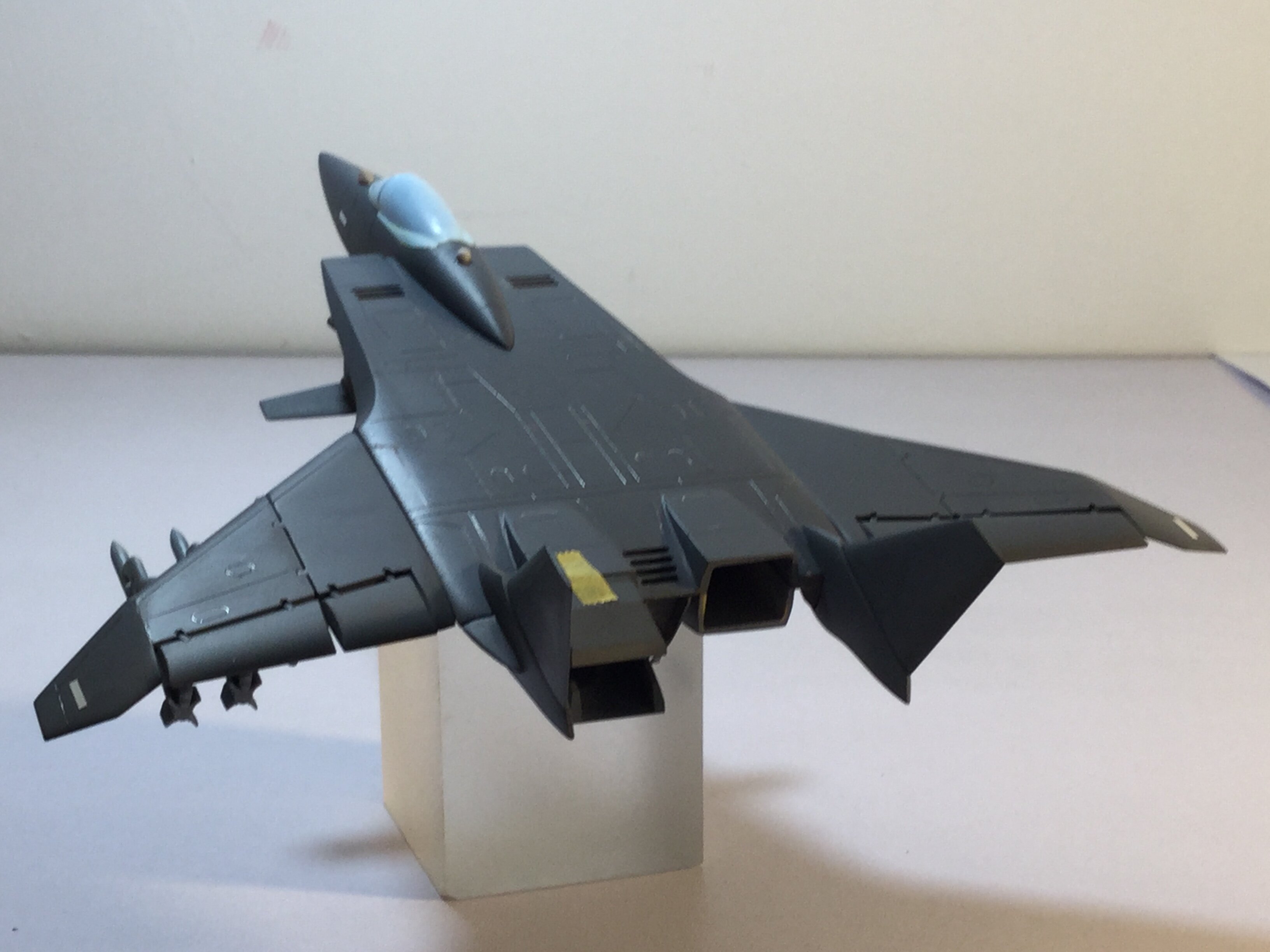
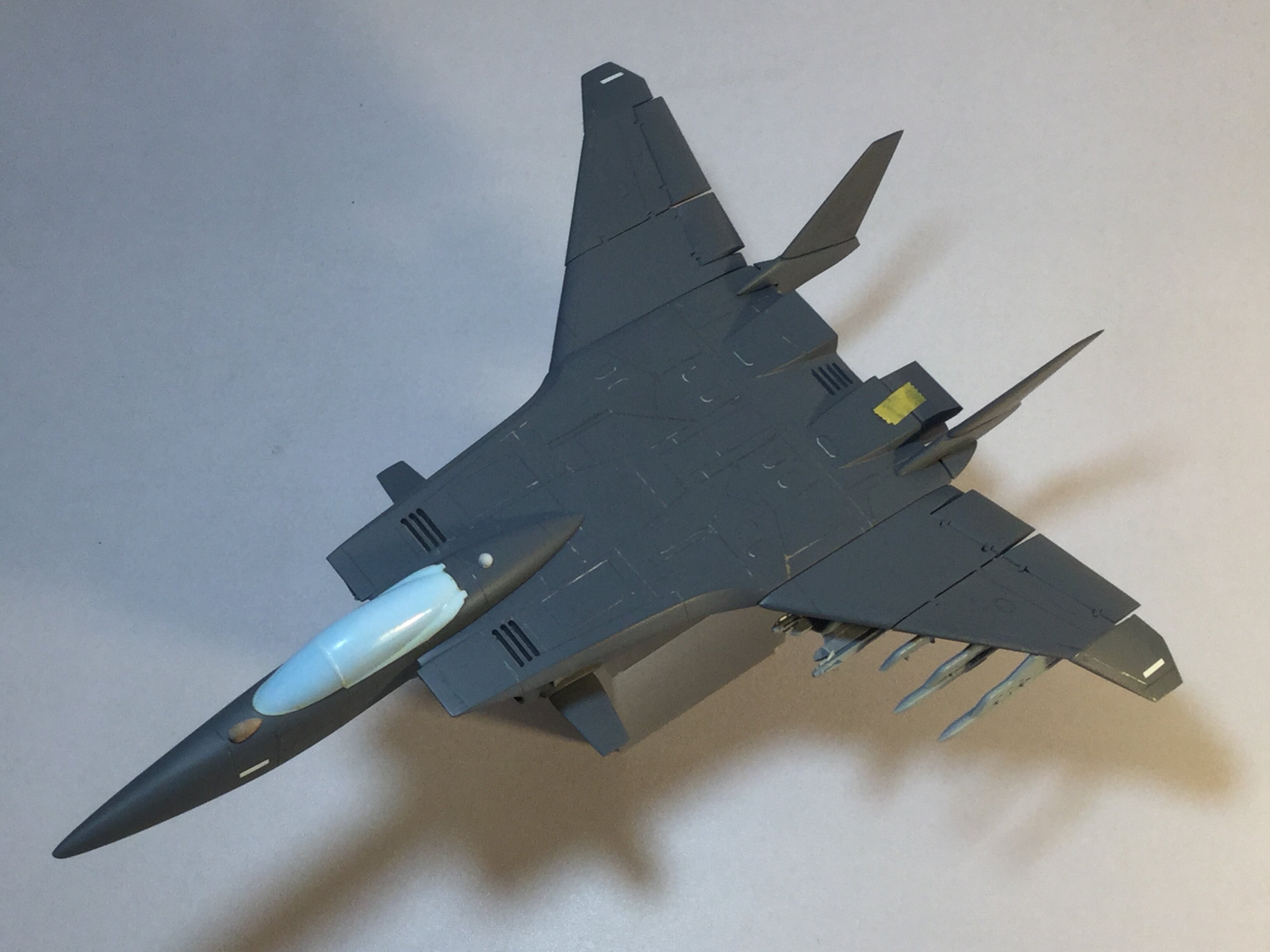
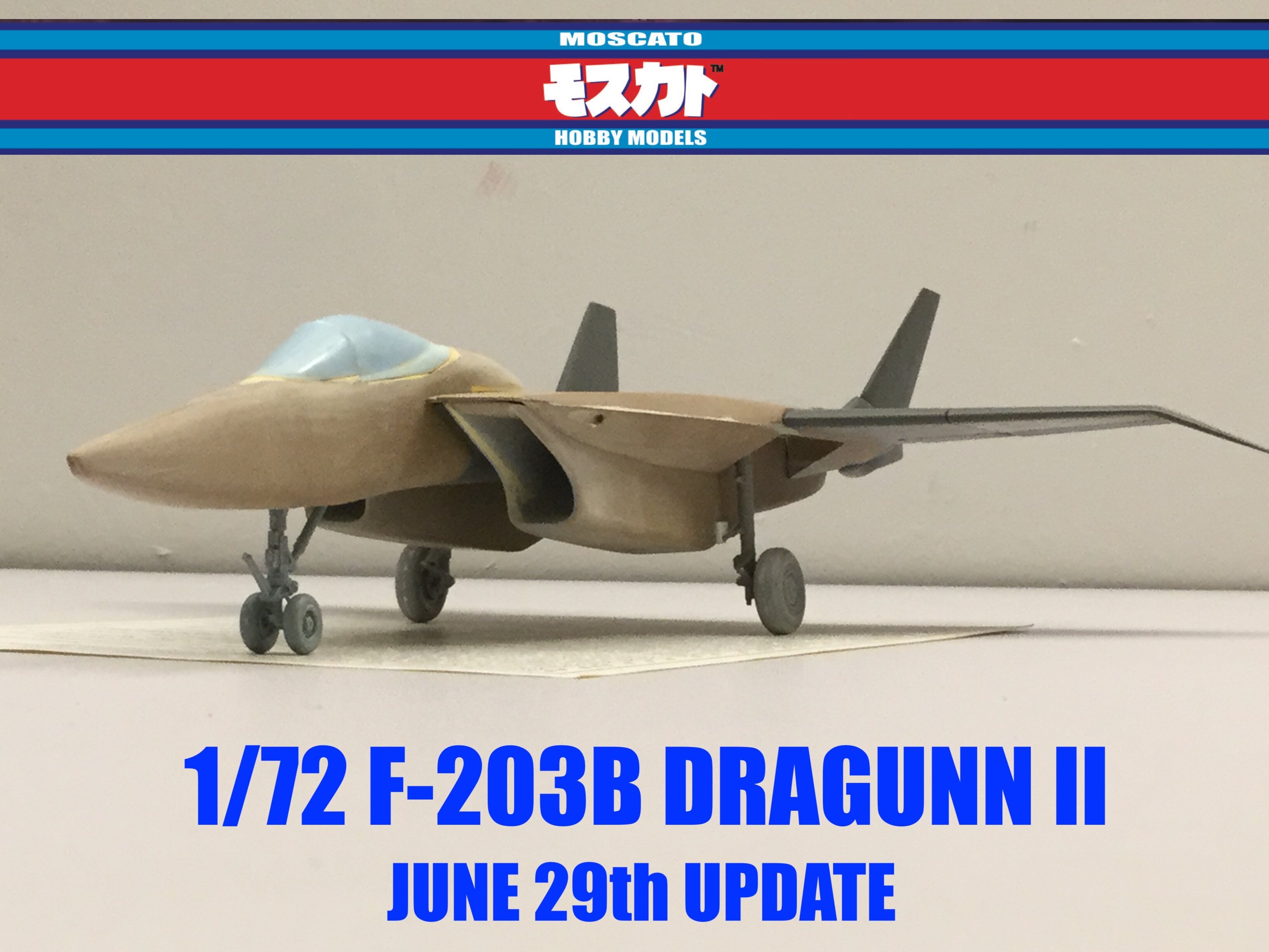
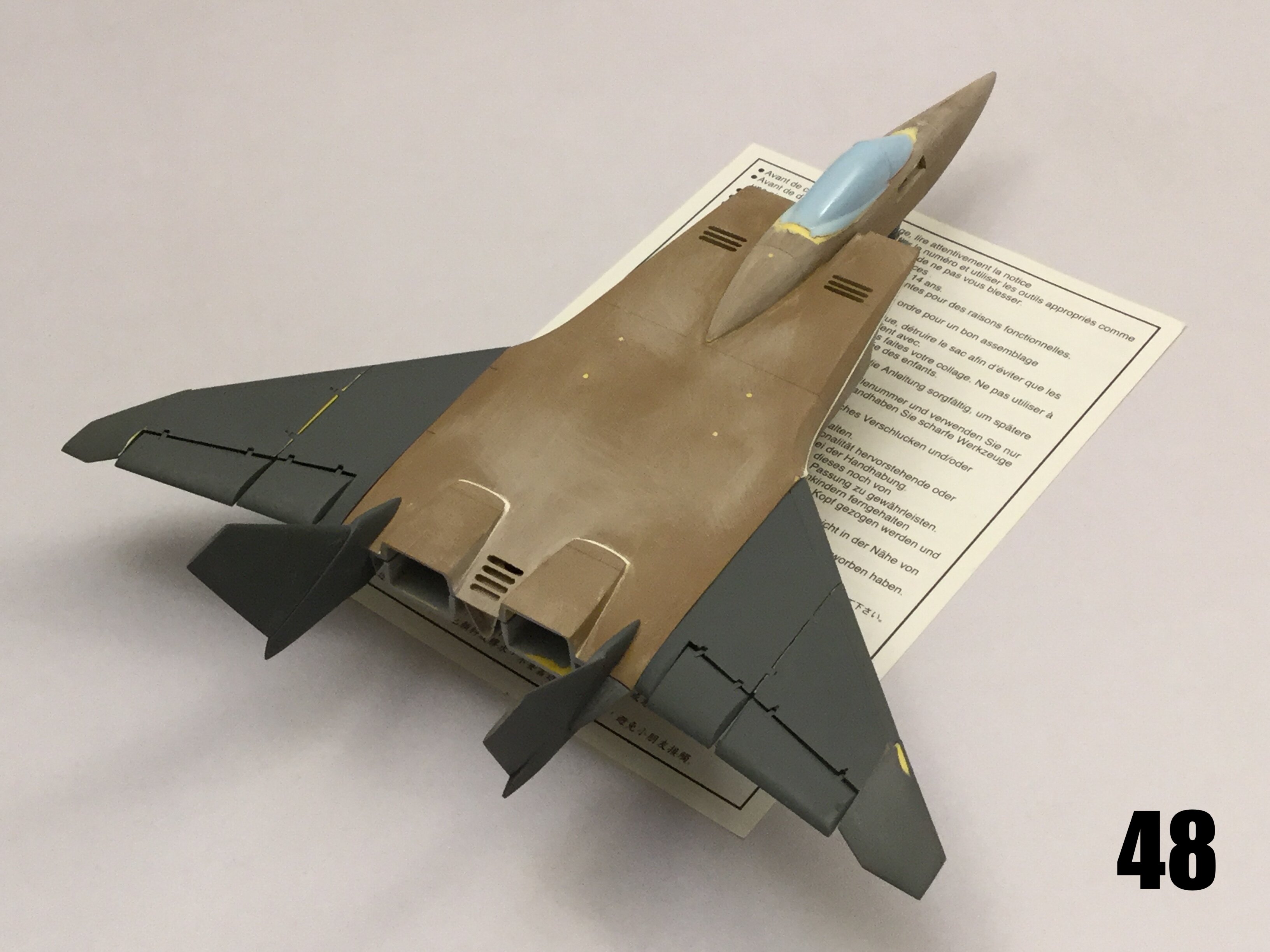
Or at least mostly finished. Behold: the F-203B DRAGUNN II Air Combat Fighter in all its glory! Perhaps it's just me who has low standards, but this thing turned out better than I could have hoped for! Please not that these pics depict flight configuration with gear up. Early next week I will have pix of the parked bird with gear, cockpit and refuelling probe. This thing is just glorious to behold, and reminds me of an F-15E. As you can see, the kit will include a centerline fuel tank and 8 medium-range and 4 short range missiles. The slight compromise here is that the missiles will need to be cast on their pylons because they're just too spindly to cast properly otherwise, and believe me, I tried! You will also have the option to build the exhaust nozzles drooping, or canted slightly upward. I've added a data link dome behind the cockpit, as well as an IRST ball on the nose. Several other small doohickies will be integrated when I disassemble and begin mold-prep. If the wings look gappy, it's just because the parts fit very tight, and I didn't want to risk damaging the masters, which I kinda already did because the tolerances are tight AF!
However nice the old Tanmen kit may have seemed, I encourage you to compare it side-by-side with this modernized version and draw your own conclusions. Mold-prep begins next week, after I do final wheels-down photography. Stay tuned!

-
Captain’s log: Thursday, June 29th, 2022.
I decided to leave the hollowing of the intake trunks until late into the build, simply because I needed to do a lot of exterior refining first. Once the intake tunnels are made, the structure becomes very delicate and prone to damage so I’d have to be very careful in my handling of the parts.
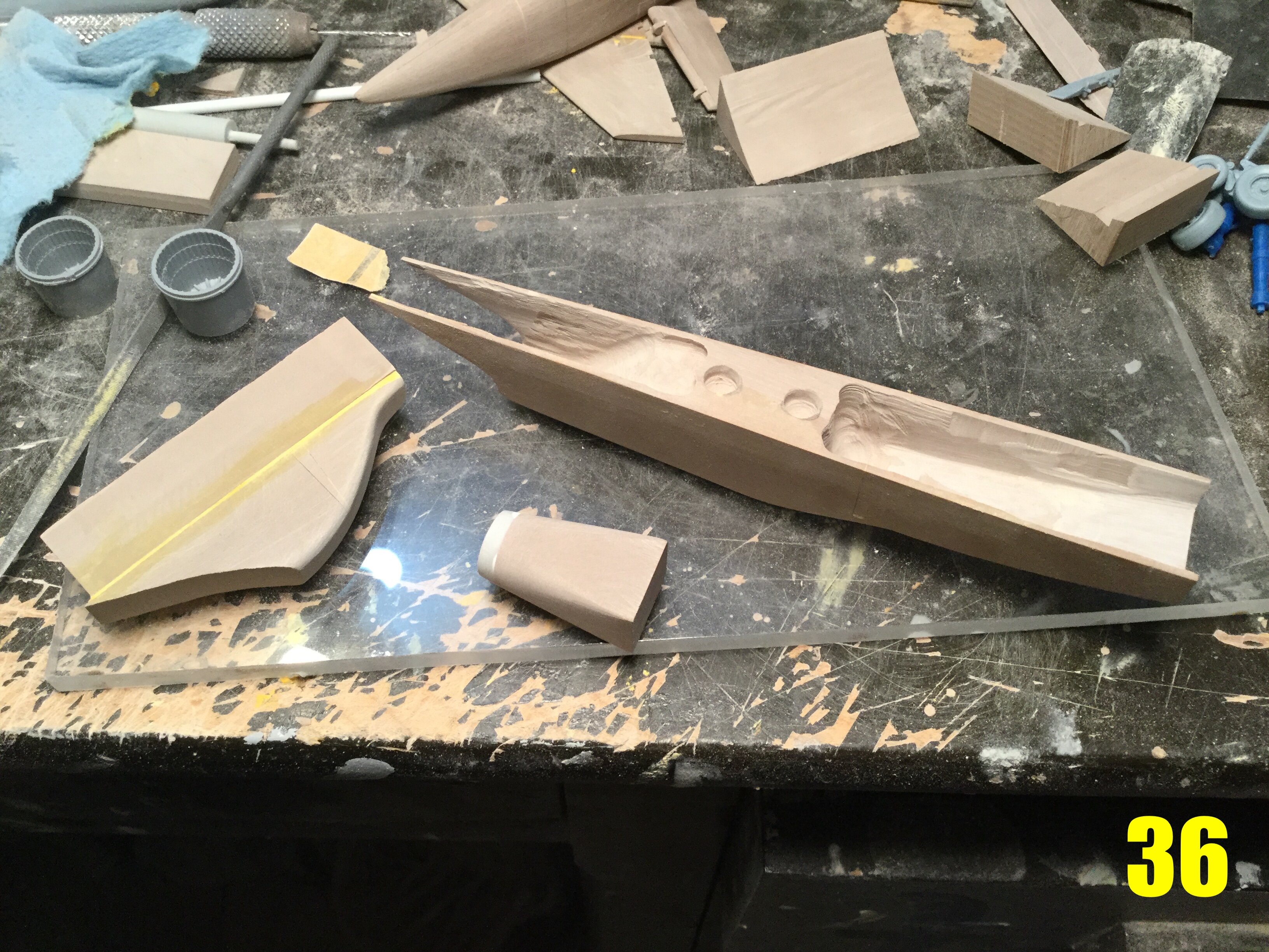
Pic 36 shows exactly what I’m refering to. Here you can see the intake body having been emptied both fore and aft, as well as the two master plugs which will be used to recreate the intake tunnel (left) and the burber can (center). The latter component is a complex geometry that goes from a circular shape to a rectangular one, which is needed to mate to the squared vectoring nozzles.
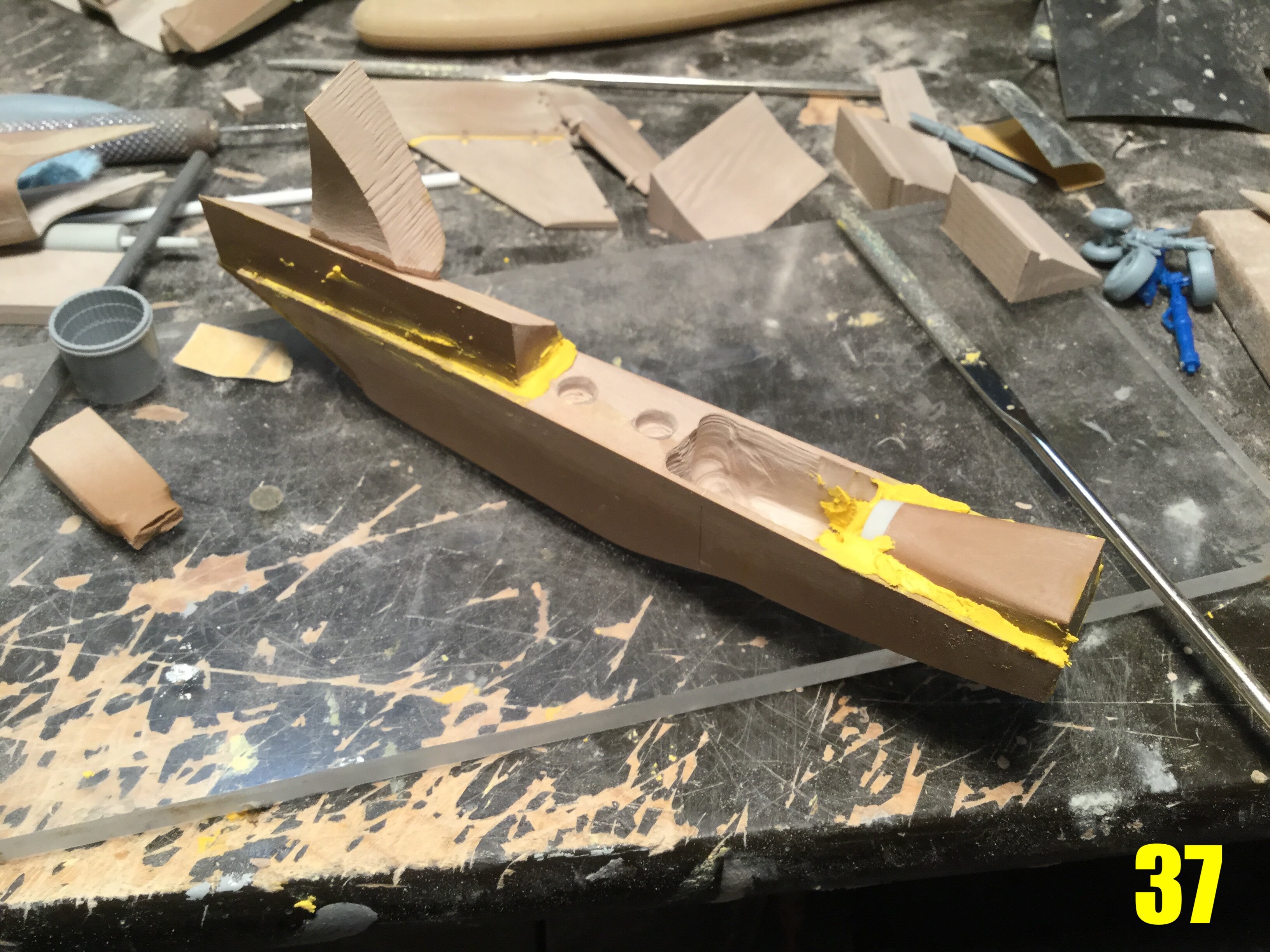
Pic 37: putty is mixed and spread onto the forms, and these are then smooshed into place within the intake bodies. This is a more stressful operation than it might seem at first glance, because the surface being created is large and the overall structure thin and fragile. If the mold release is improperly applied, the only way to separate the buck from the part would then be to destroy the entire intake assembly!
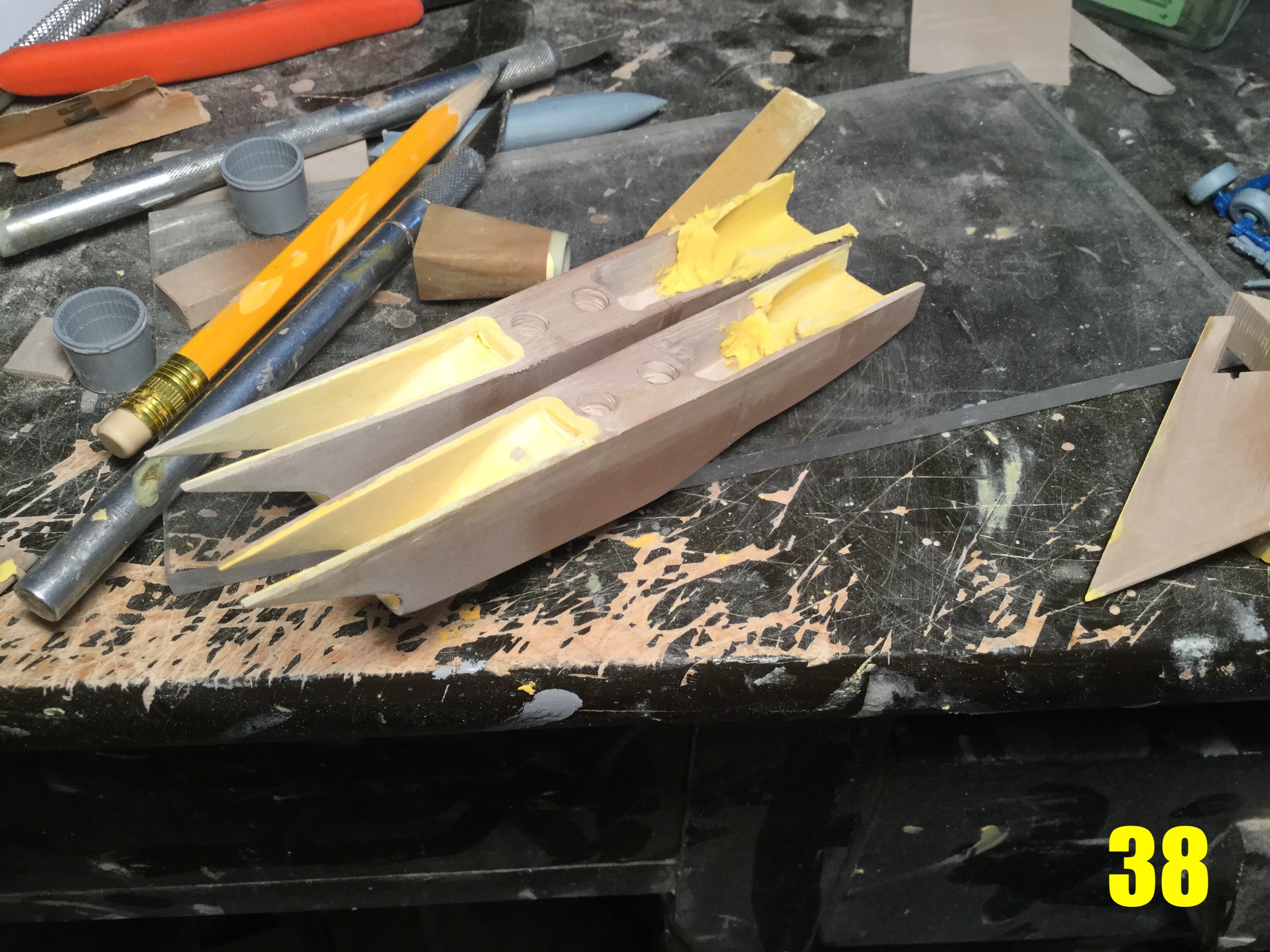
Pic 38: thankfully, I mostly know what I’m doing, and the procedure was a success! Here you can see that I already began removing some excess putty around the intake area.
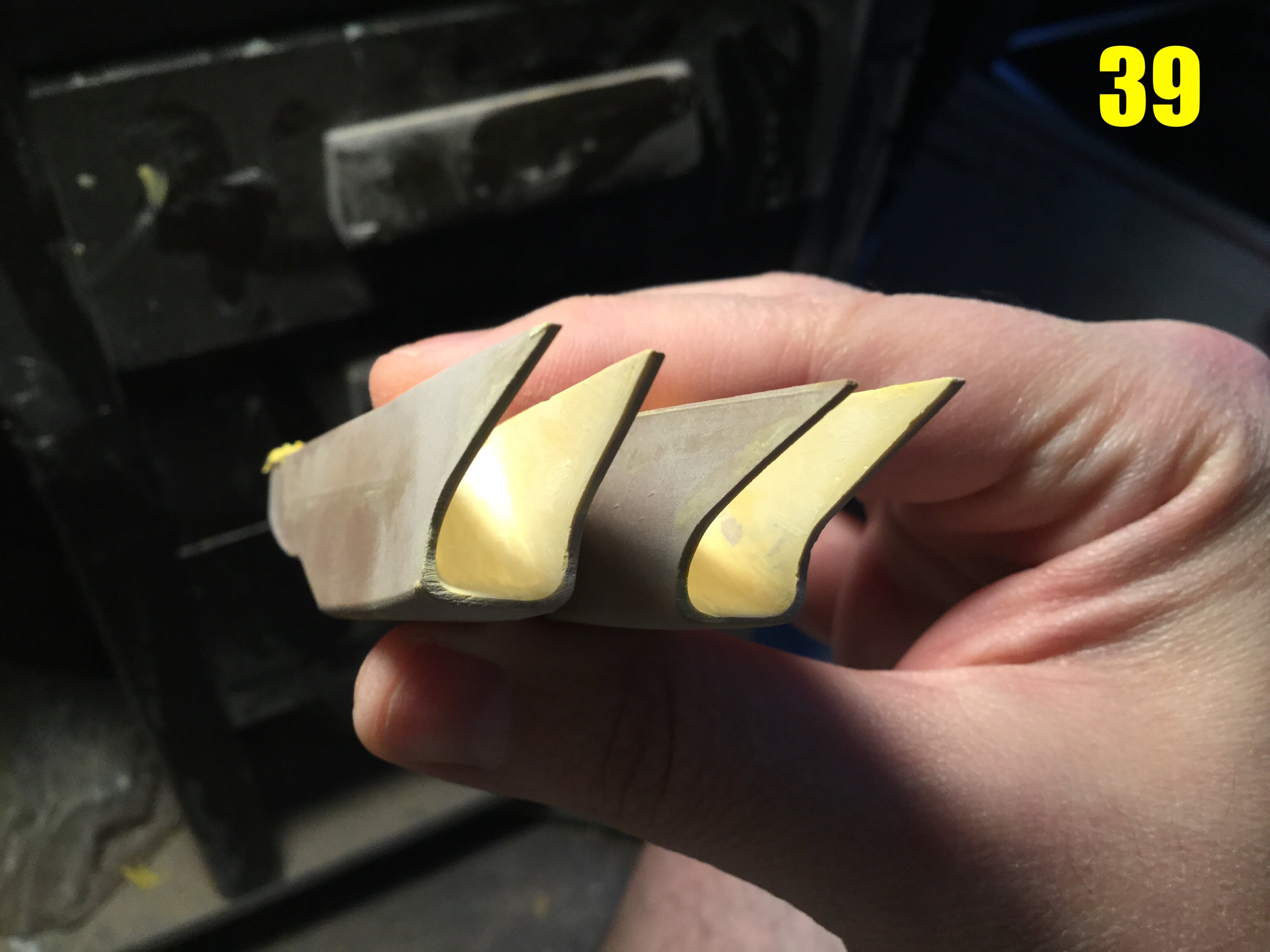
Pic 39: the complex RCS-minimizing intake tunnels are looking quite good. The outer wall is still quite thick, and this is by design: the final thinning will be done when the upper roof/intake ramp is added to reinforce the structure.
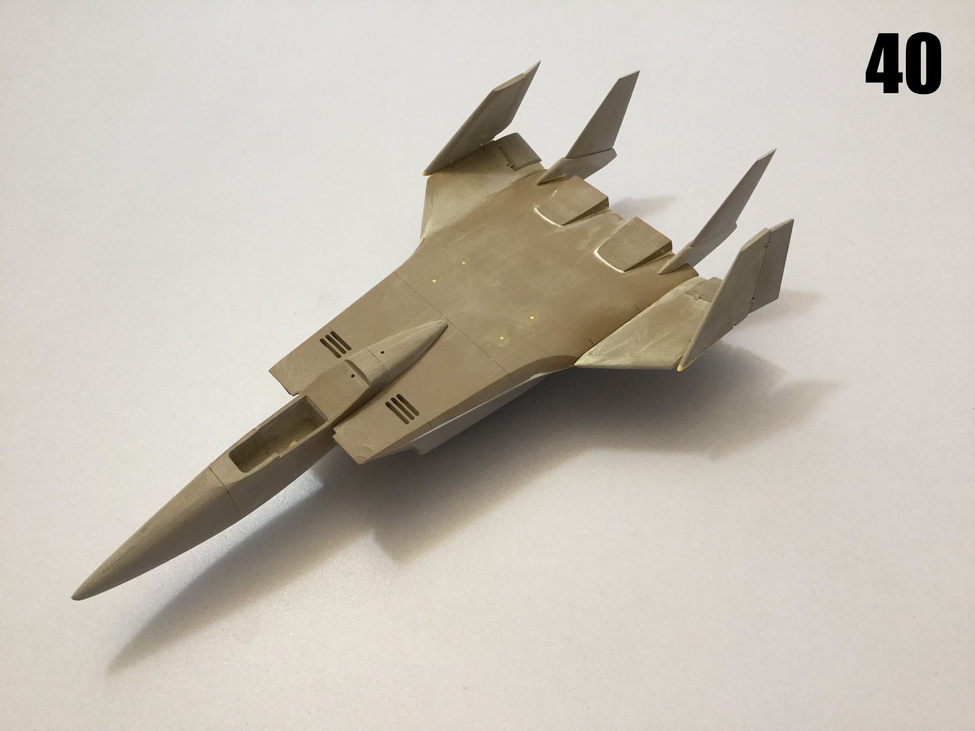
Pic 40: I forgot to show the sto-wing feature, so here it is: notice that the wing tips have not yet been added.
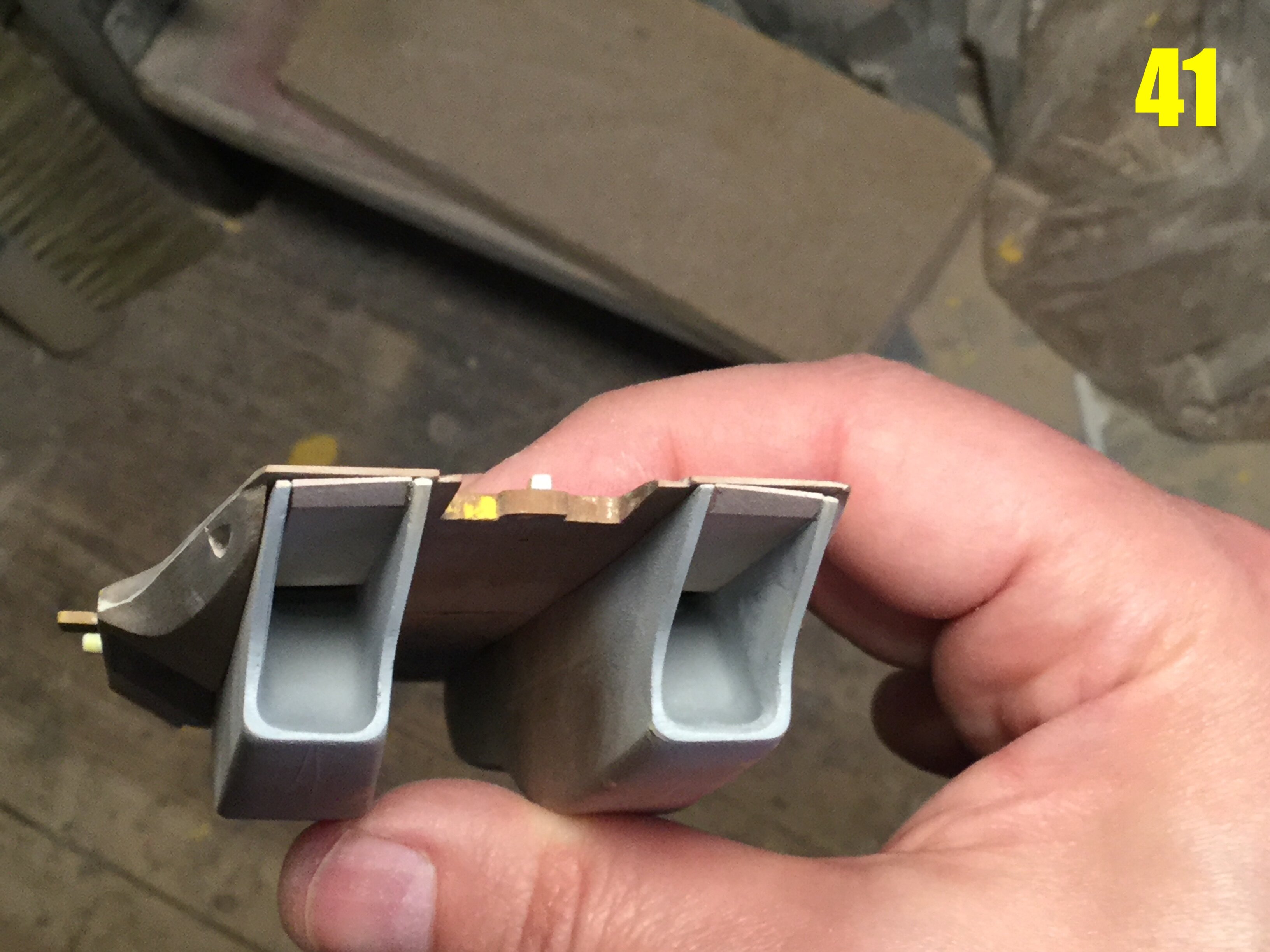
Pic 41: the intake tunnels are done! If the left one looks rough, it’s just because I sanded down some of the primer. The intake ramps are in the fully open position, though if the build permits, I will include an add-on the represent the lowered ramps.
Pic 42: the burner cans are also done, though these stil feature a seam. I’m debating whether it’s best to leave these smooth and let the builder fill them, or try to mask the seam with ribbing of some sort. As much as I would have preferred a seamless unit, the complex shaping of the part made this impossible.

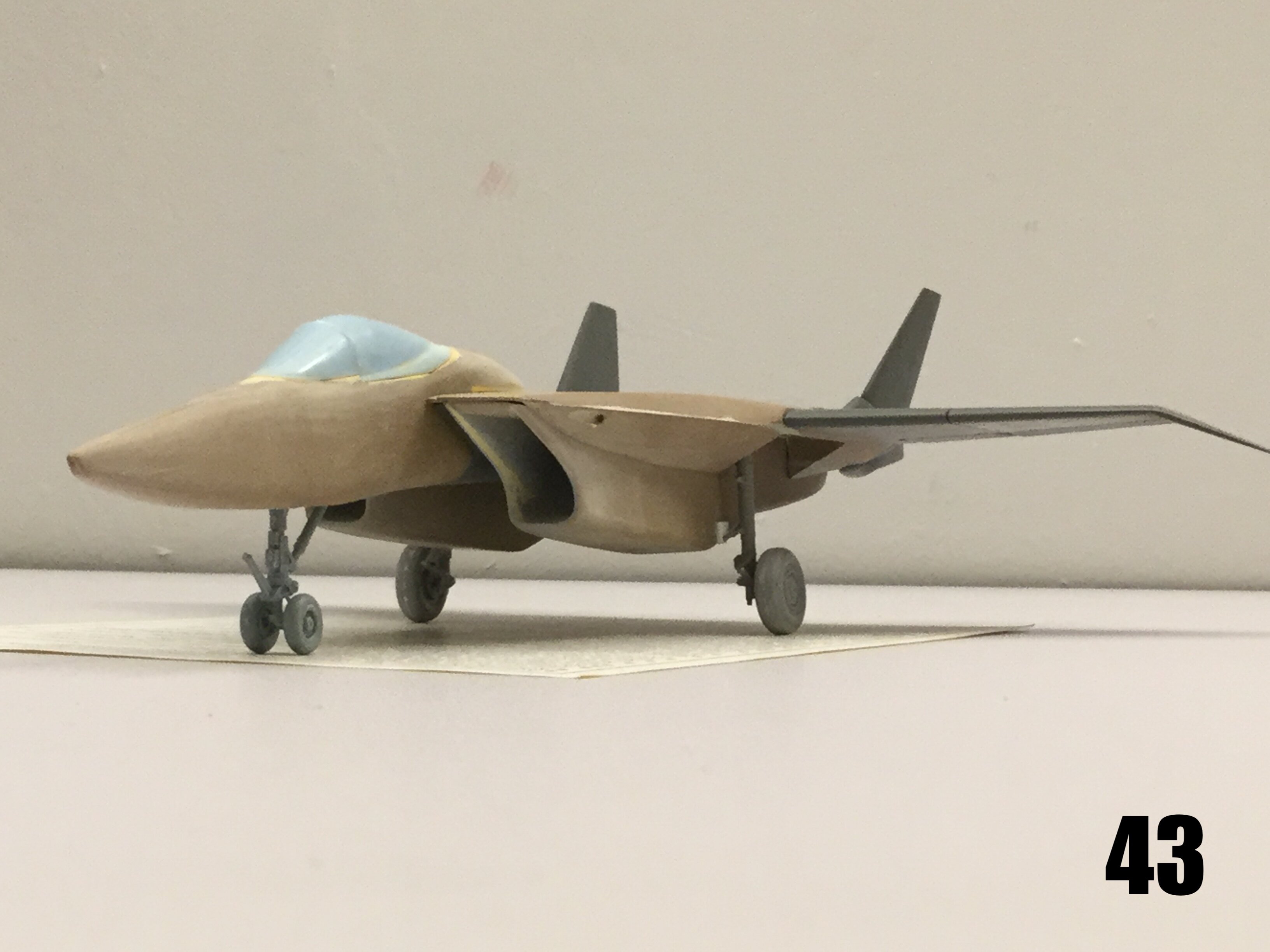
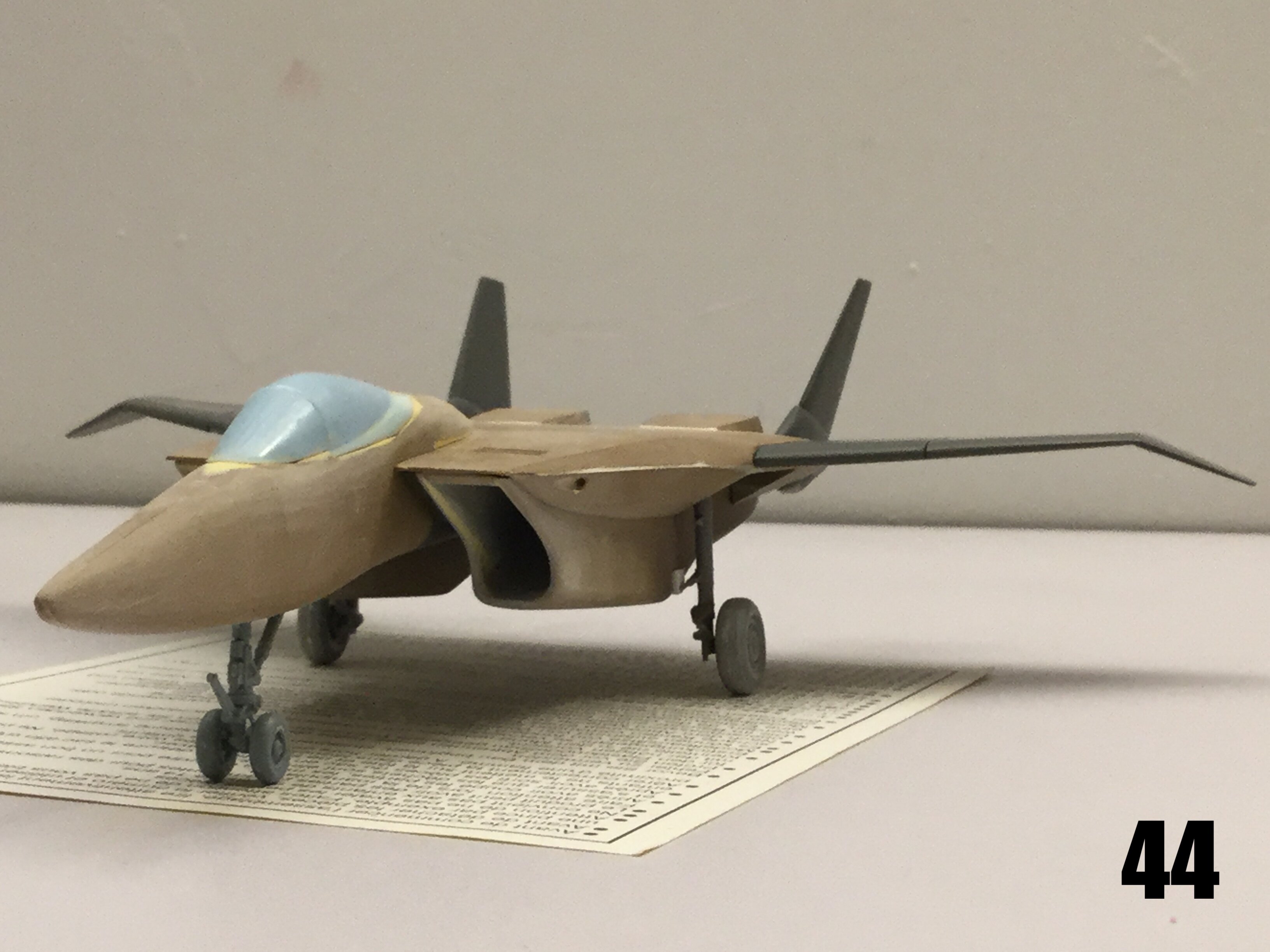
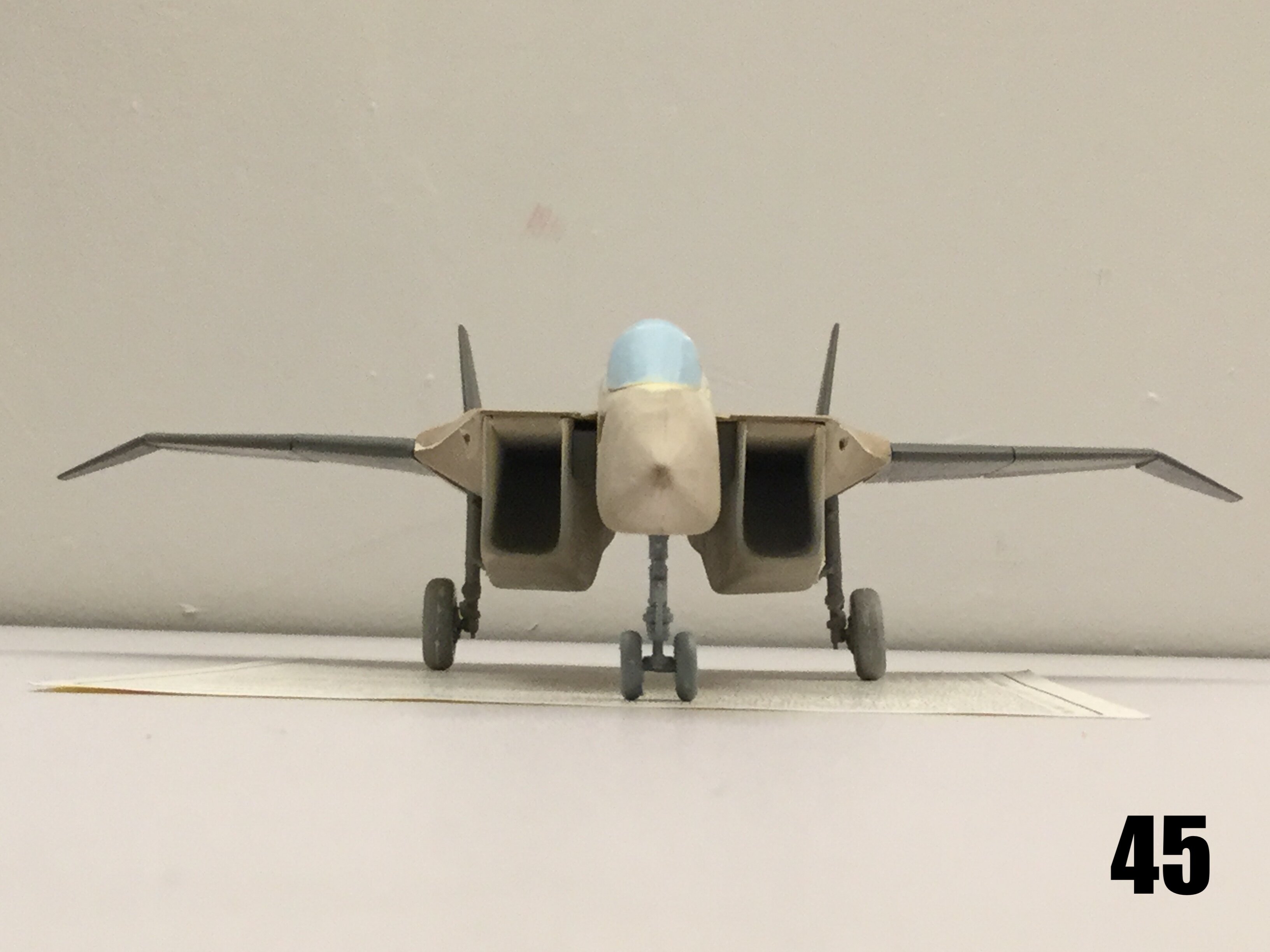
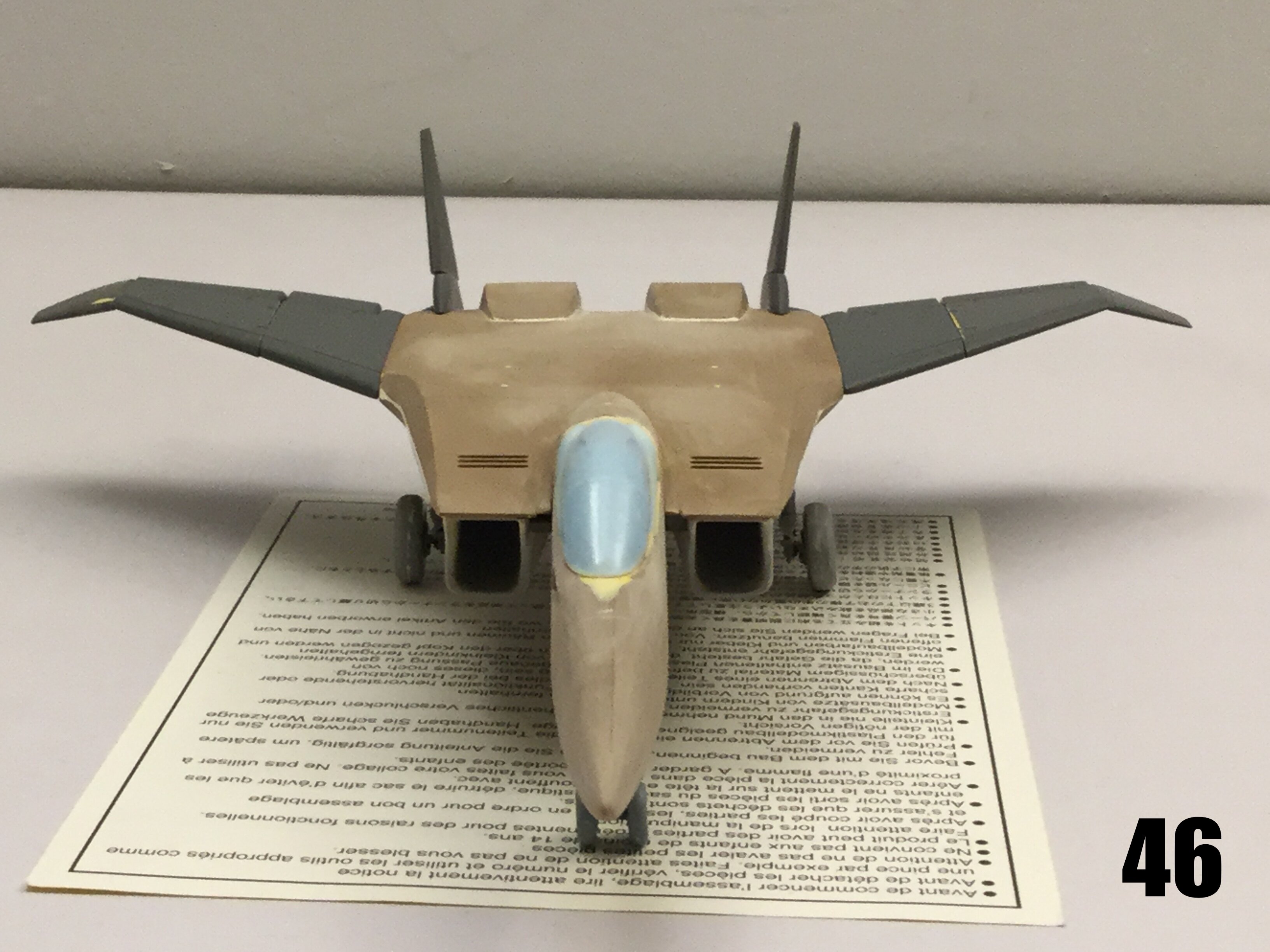
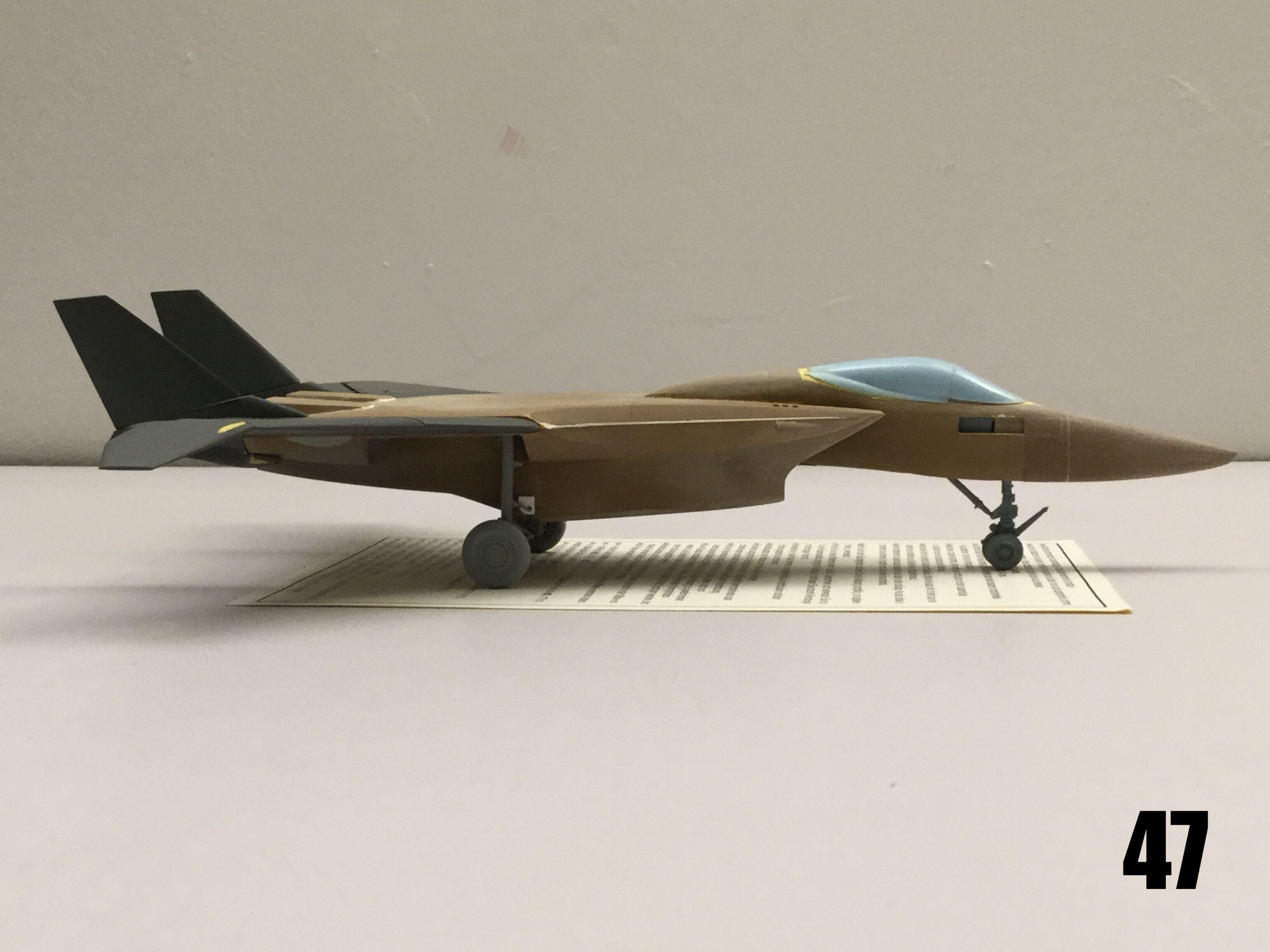
Pics 43-48: what a beauty! I stole the main gear from an SU-27, and the nose gear from an F-18, and they look excellent. You can also see the refuelling probe housing on the starboard forward fuselage, which you will have the option to build open or closed. I also have missile pylons in the works, but I need to make mold duplicates. I have already begun priming and detailing, and should have it all mostly done by July 8th or 12th. I think you’ll be quite pleased when you see the end result. Stay tuned for the grand finale!
-
On 6/25/2022 at 4:49 AM, Flarpen said:
Hi Cap.
Are you going to hollow out the engine air intakes?That's what I'm currently working on.
-
Quick 1/72 Dragunn project update: Friday's progress report will be pushed to next week because sooo much puttying.

-
2 hours ago, electric indigo said:
Now that you mention MiG, I can see it as a mix of an F-15 and the 1.44

That bodes well, because I may end up using some SU-27 weapons pylons.
-
Captain’s log: Thursday, June 16th, 2022.
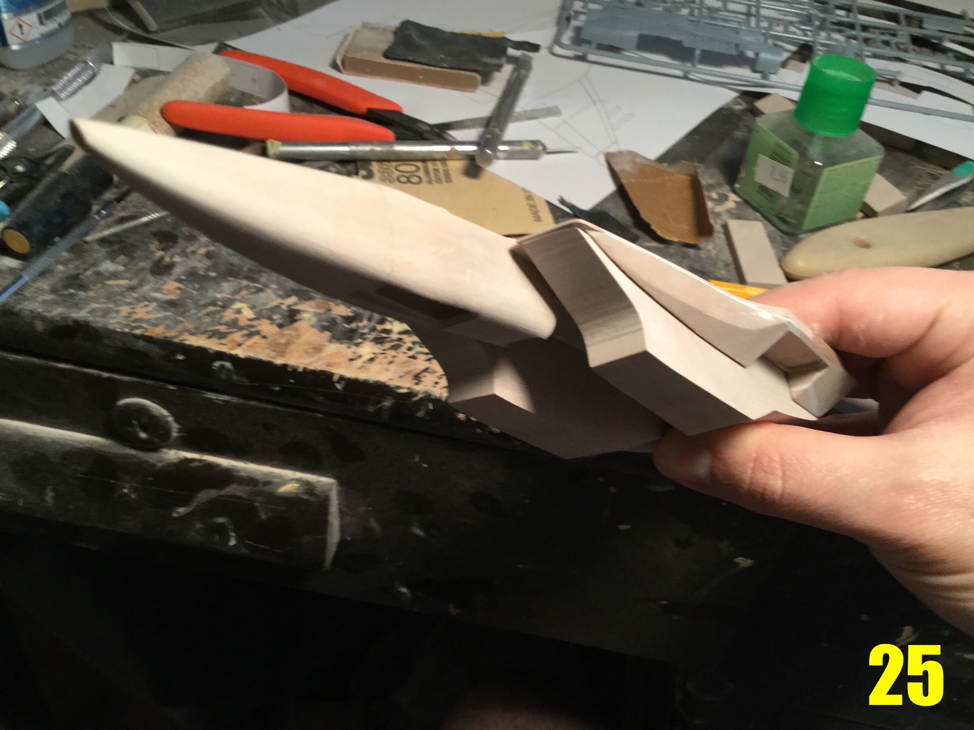
Pic 25 shows off some very VF-1-inspired lines, which only makes sense as its predecessor. I can’t tell you how much fun I’m having with this thing! It’s such a nice change of pace to be able to play pretend aerodynamicist, even if it’s only for a little while.
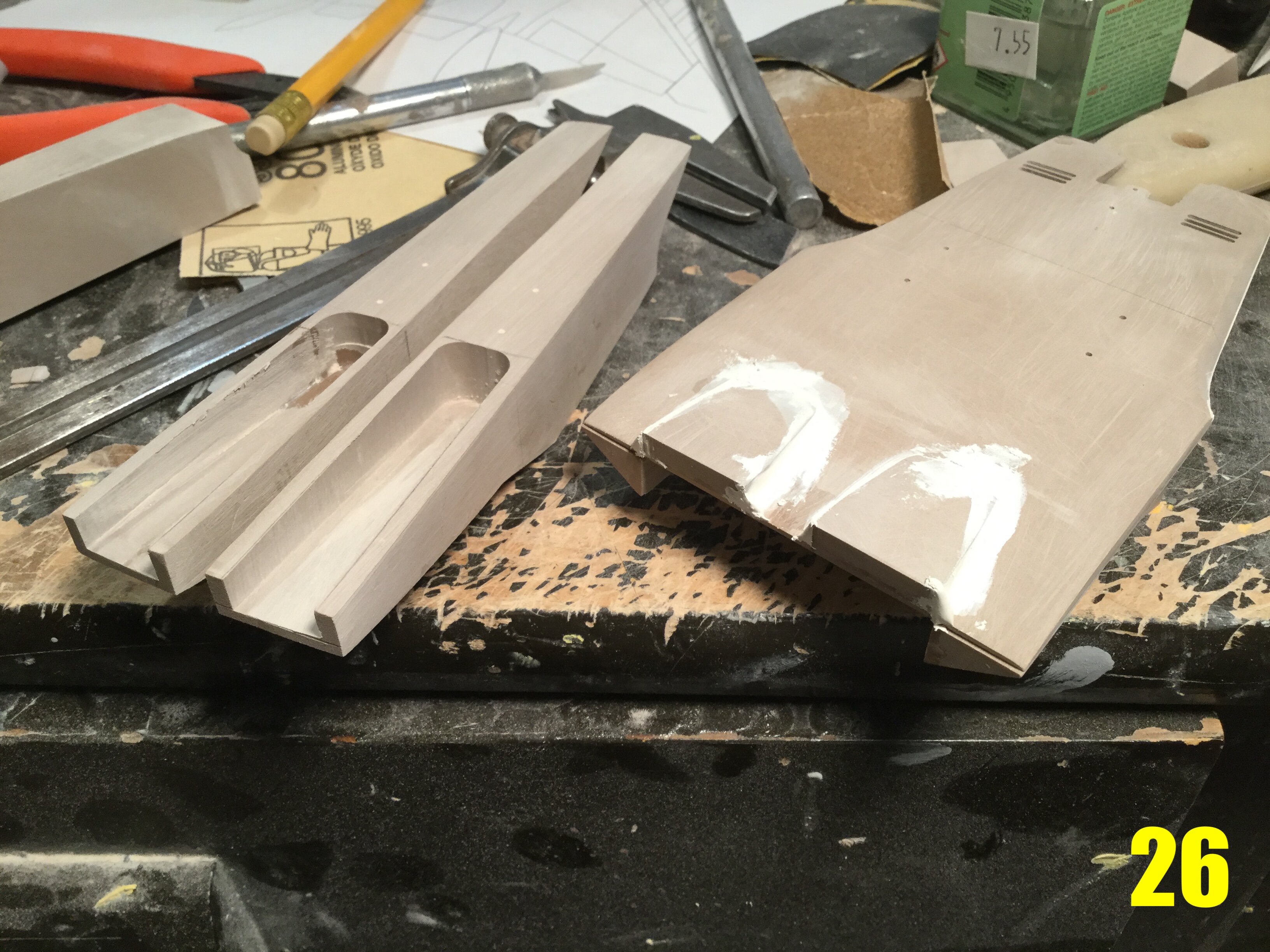
Pic 26: the engine nacelles being hollowed-out while the upper surface is modified with the appropriate shapes. Frankly, the aircraft has way too much of its weight distributed aft (engines, wings, stores) so I need to scrape as much weight out of this area as possible to keep her from being a wheelie-bird when she sits on her gear.
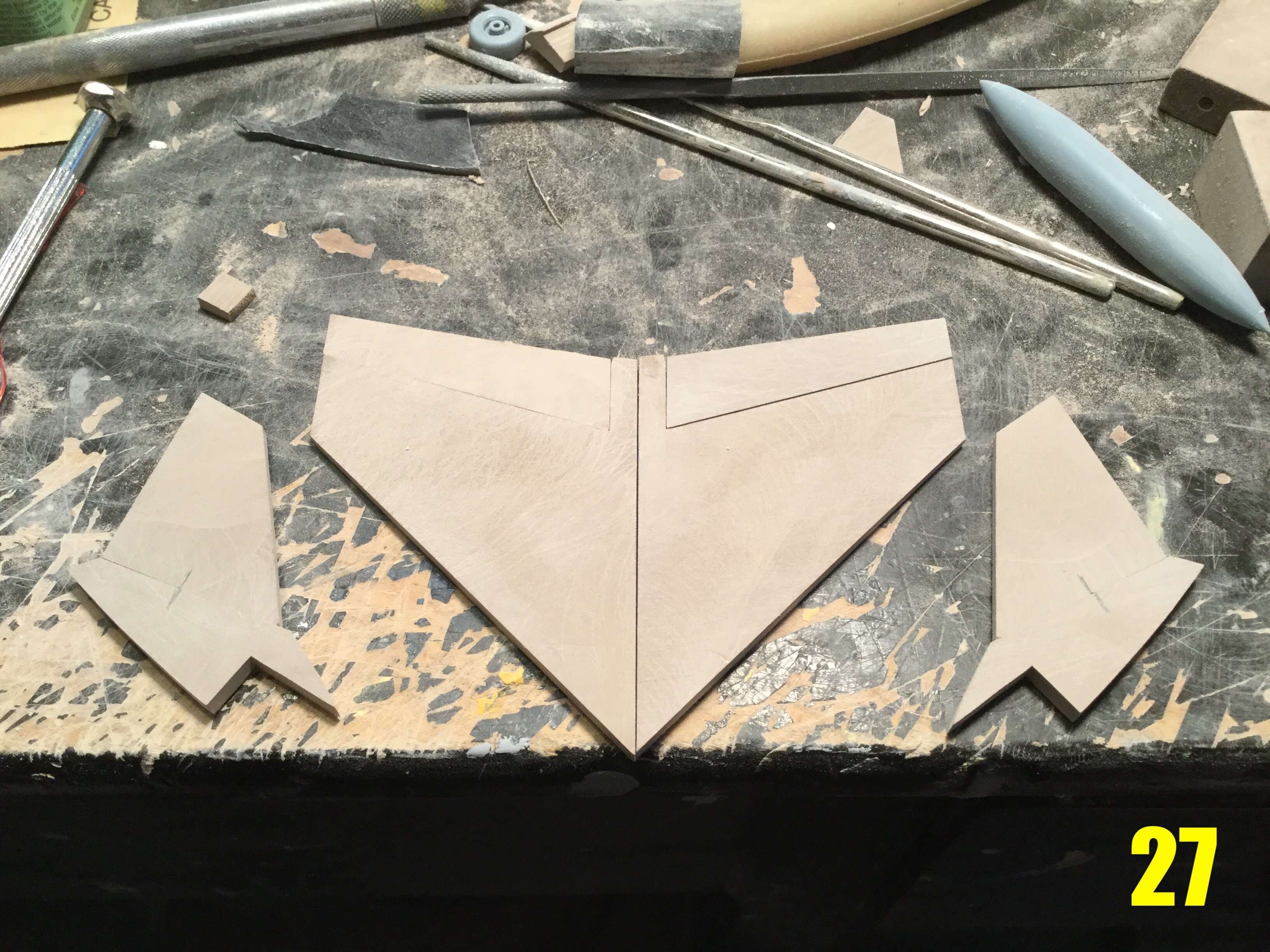
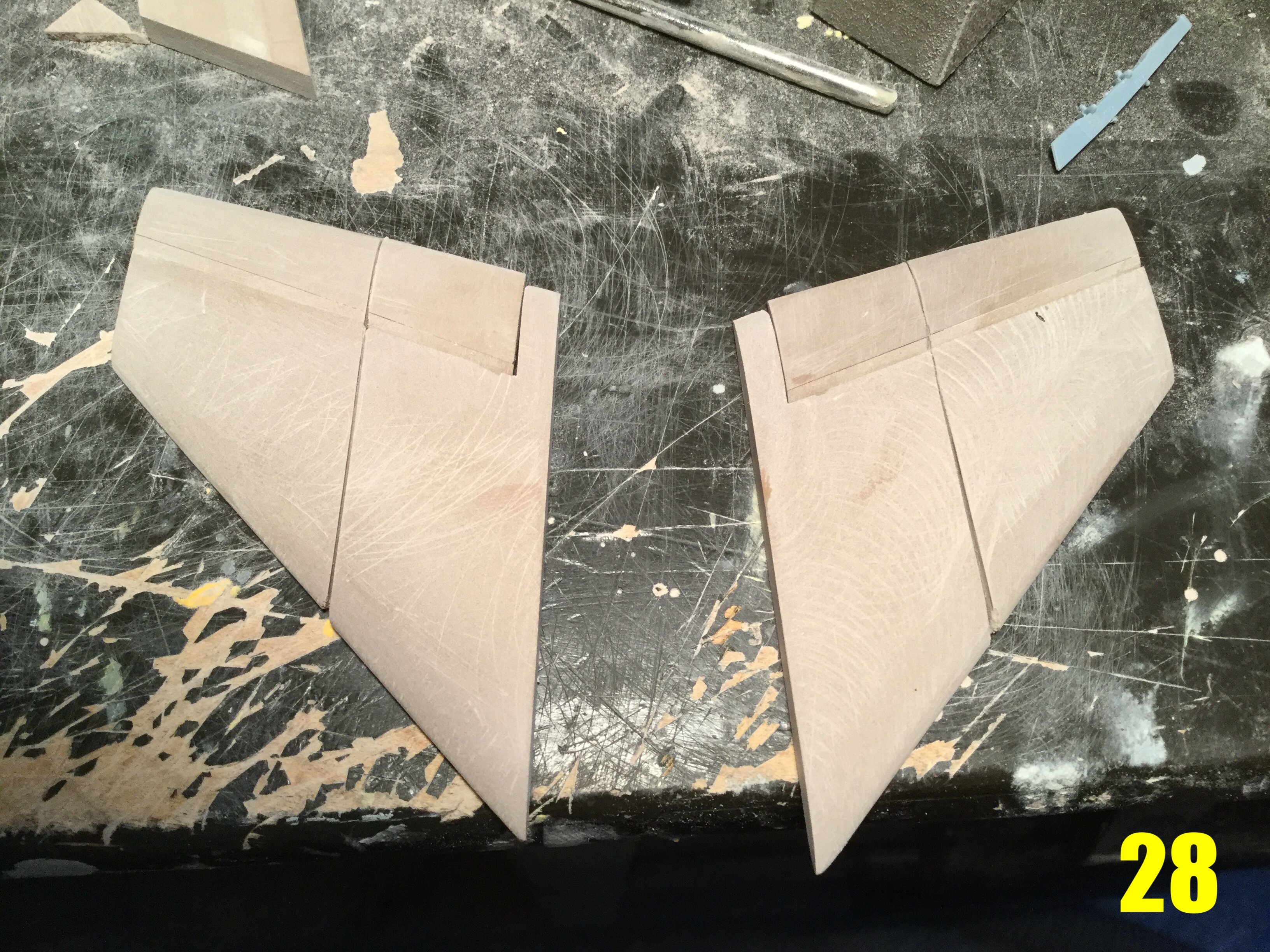
Pics 27 and 28: wing surgery underway. The wings need to be split for the flaps, and then again for the sto-wing hinge. Because of the thrust-vectoring nozzles and secondary ventral thrusters, I didn’t think the plane would need fowler flaps, so conventional units are used. The rudders are all-flying control surfaces, and I modified the pivot to make sure that all the control surfaces don’t interfere with each other. They’re a little shorter than they appear in the line-art, but that’s because se sits tall on her gear and hangar clearance is a real thing.
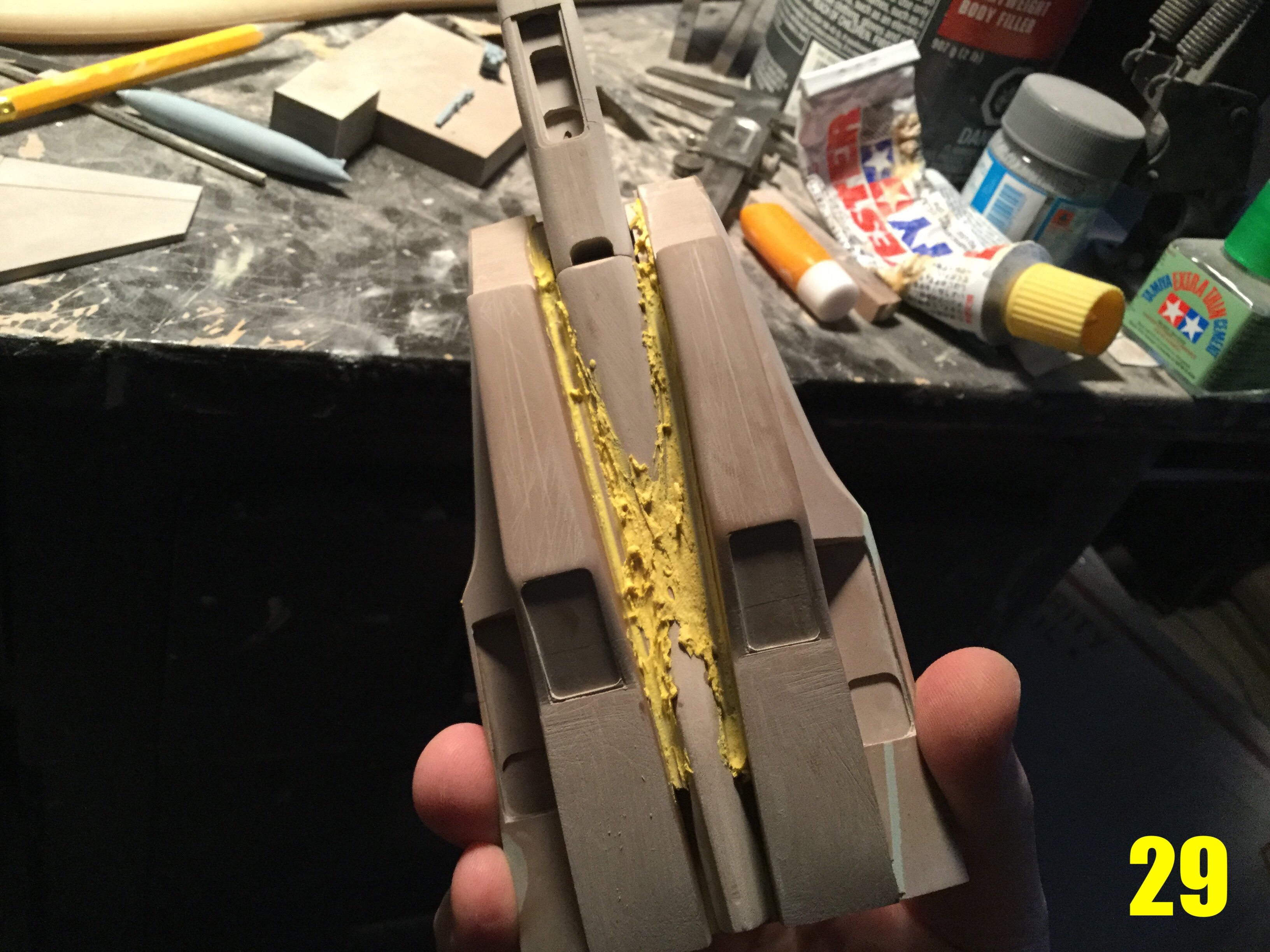
Pic 29: having fun with putty! There are lot of intersecting parts in this area that had to be mated and smoothed. Truth-be-told, the way that central ventral fin bulges down at the rear is absolutely horrendous for drag, and can also interfere with the aircraft’s take-off AoA, so I toned it down a bit. It’s still an interesting shape that can house lots of sensors/jammers/fuel dump pipe, and will also feature an arresting hook… because carrier landings!
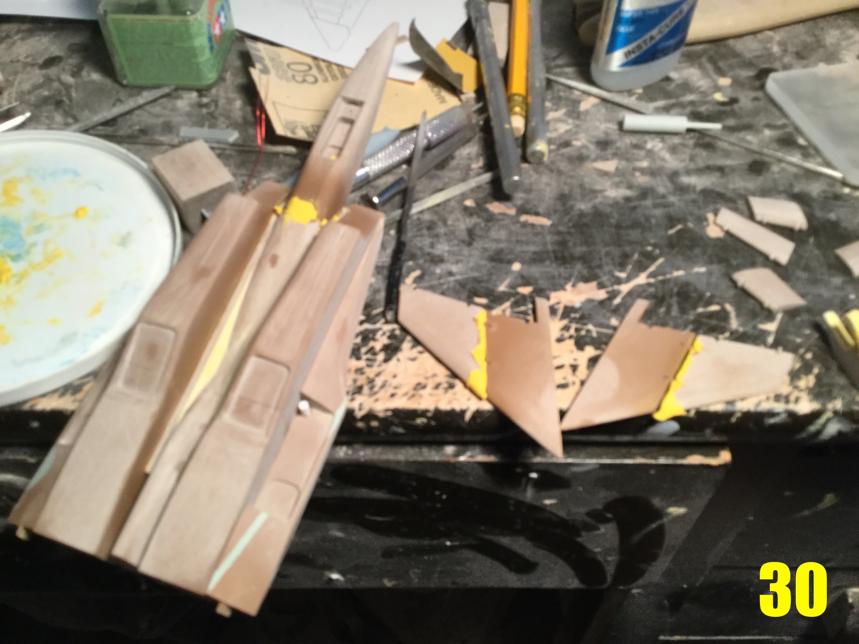
Pic 30: even more putty! Here you can start to see the shapening of the ventral area, as well as progress on the wings, which now have all the appropriate hinges. I’ll be adding hard points on the engine nacelles, but I’m also considering using that ventral tunnel to house more munitions, much like we see on the F-14.
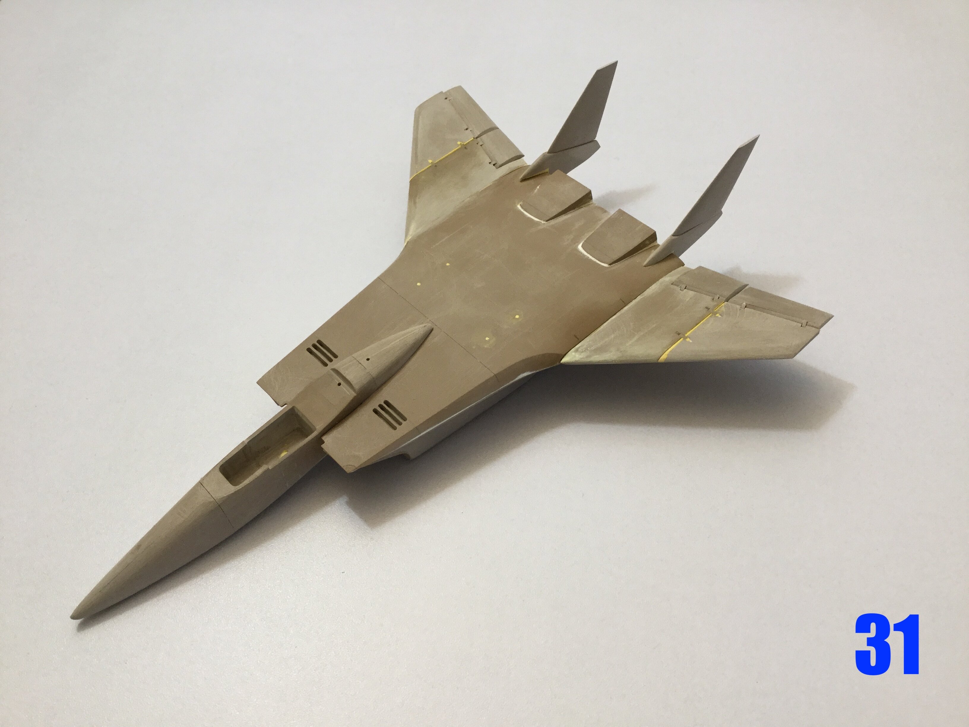
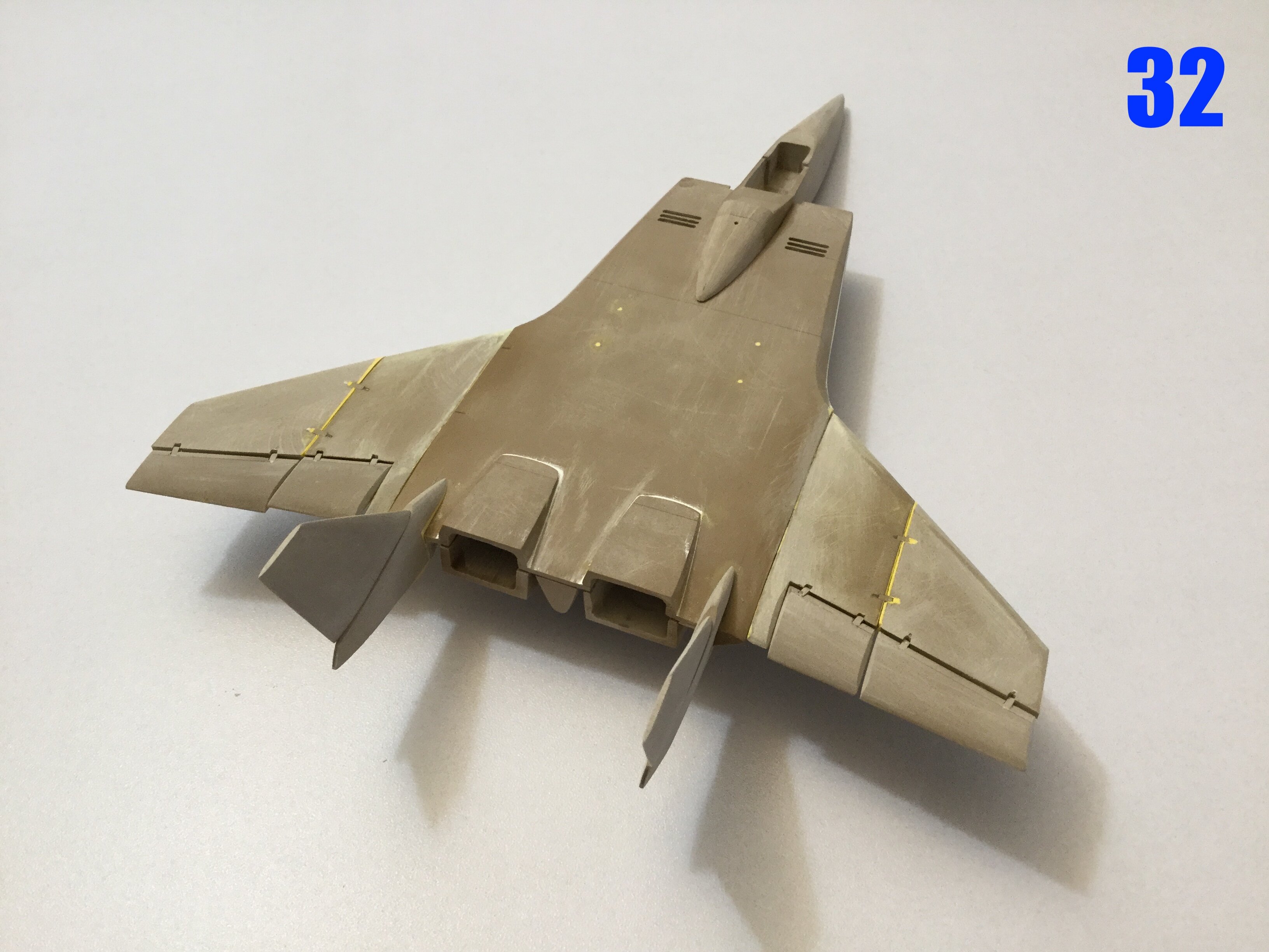
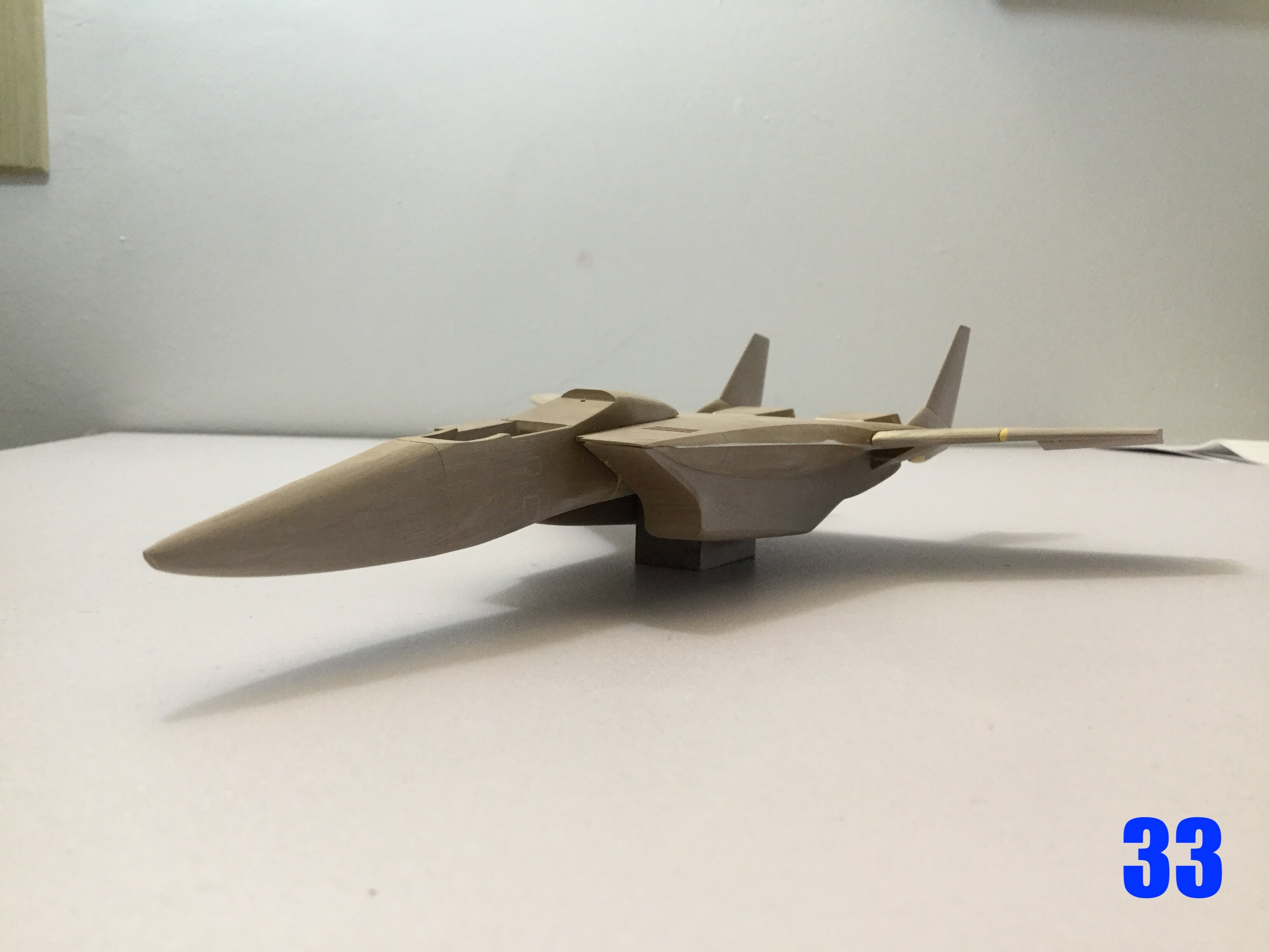
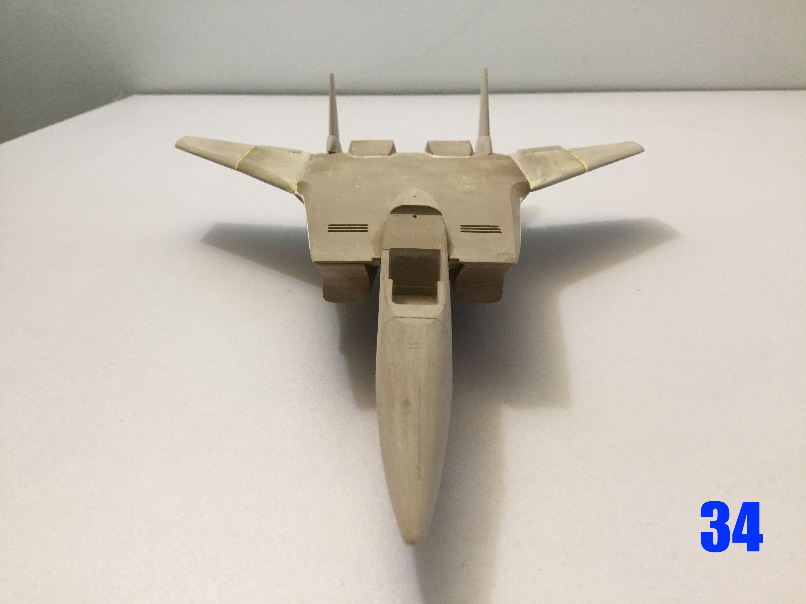
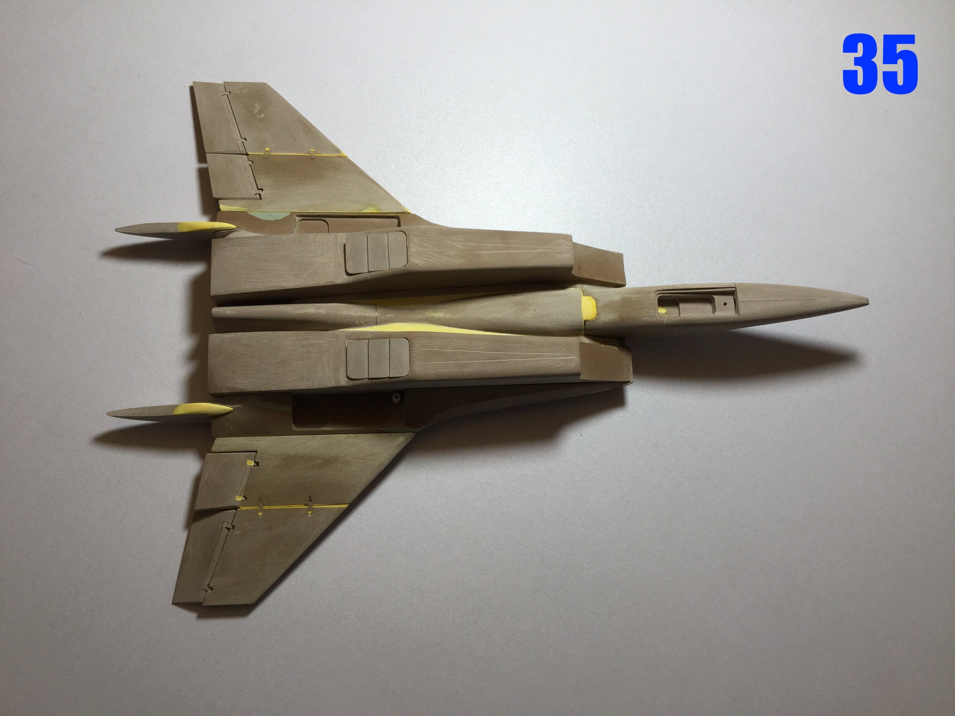
Pics 31-35: here’s the fuselage, now with partial wings. I’m leaving off the wingtips until I have the rest of the wings scribed & primed. She looks very MiG-25 at a glance, and I love it! Bear in mind that some parts are just tacked together, which is why it looks wonky. Next week I’ll be looking to molding the canopy and start adding details, so stay tuned!
-
It's definitely worth seeing a second time, and more, just because it's such wonderful fighter porn. I say this despite some rather blatant creative liberties taken by the writer & director.
-
2 hours ago, Thom said:
Looking fantastic! So are they all going to be made out of wood..?
Not wood, modelling board, then resin for the kits.
-
Captain’s log: Thursday, June 9th, 2022.
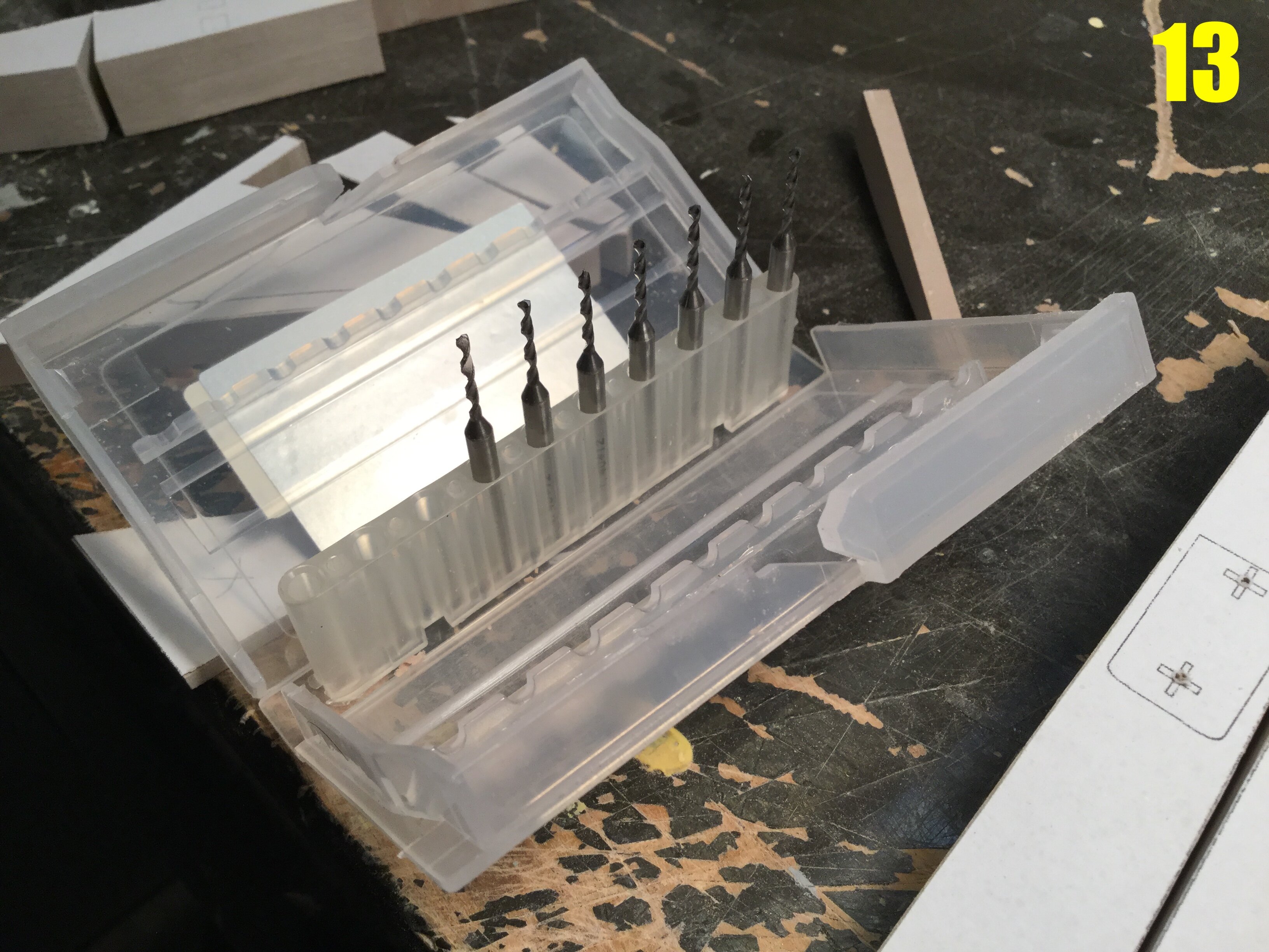
Pic 13: say hello to my widdle fwiends! This is a pack of 1.3mm bull-nose milling shanks I bought on the internet a few years ago. They work wonders for tiny details, and for a subject with lots of fine detailing like this one, they come in very handy indeed.
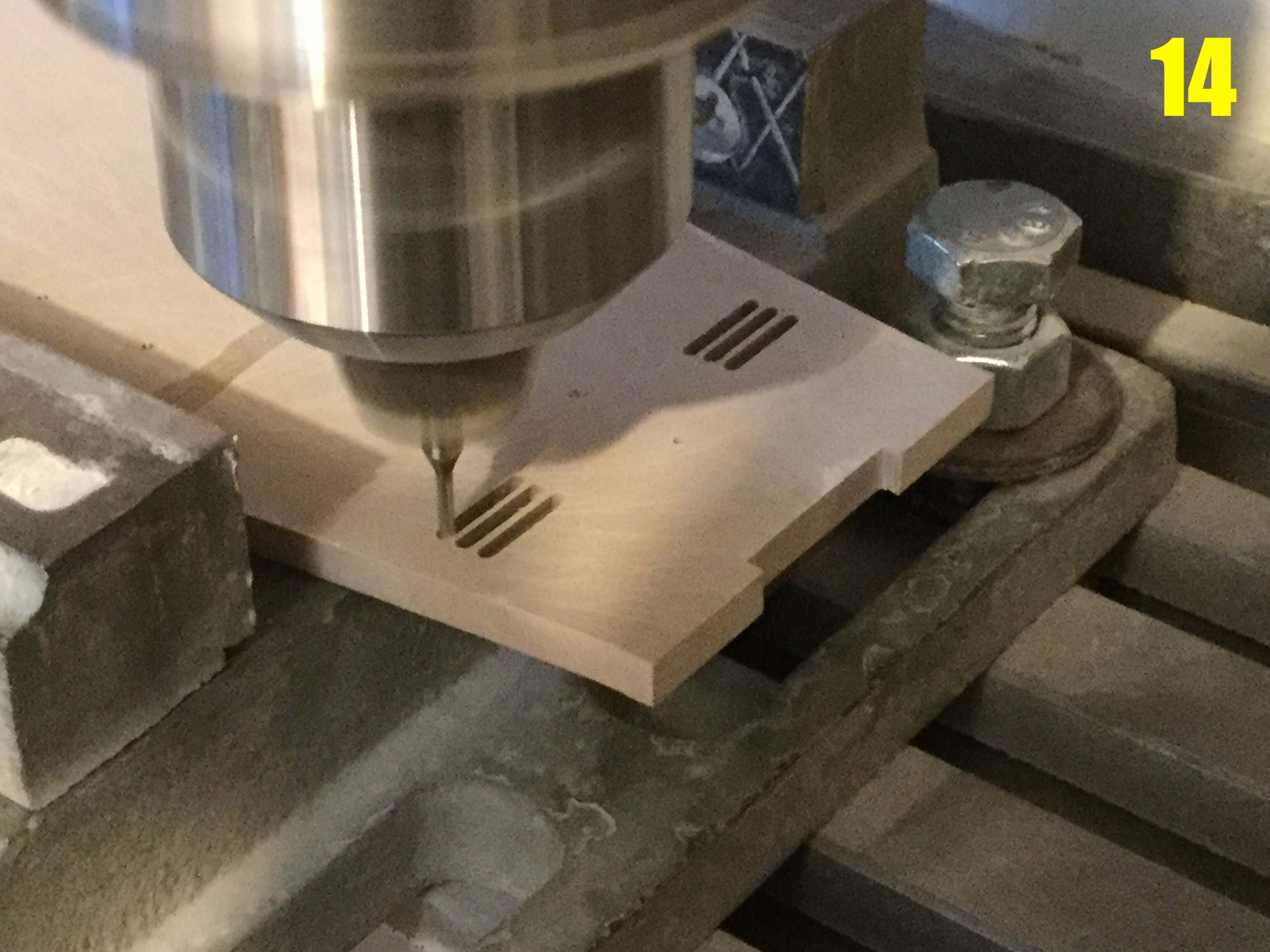
Pic 14: those very same milling shanks hard at work creating some of the boundary layer bleed slots on the upper fuselage of the fighter. In operations like this, your cutter has to be sharp, otherwise the modelling board may snap and utterly ruin the work.
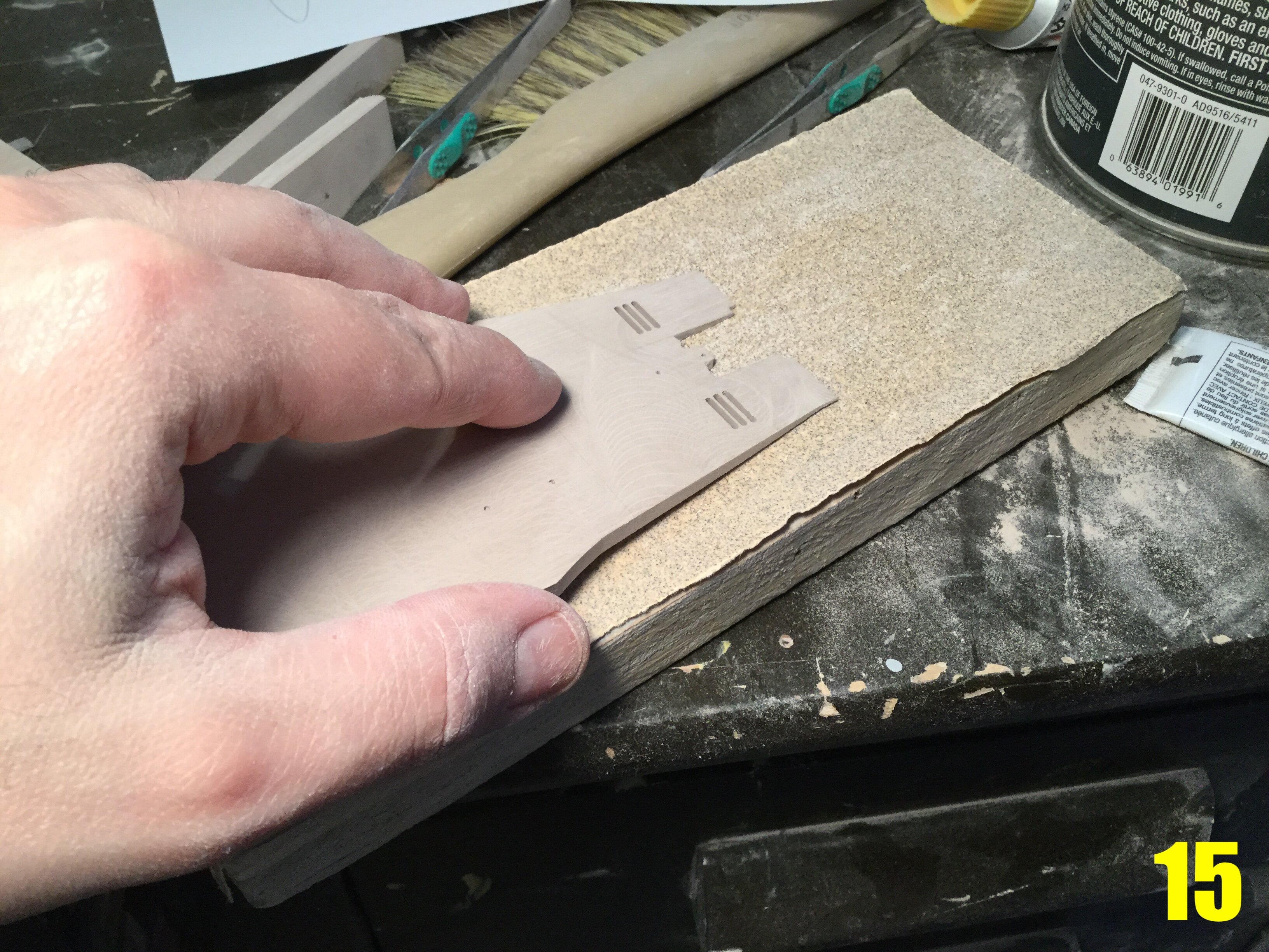
Pic 15: that same upper fuselage part, now being sanded to a fine point for the splitter plates. While I would have prefered to wait as long as possible before making this part so sharp & delicate, it’s a critical detail around which other parts will be formed, so away I go. Lots of very gradual, manual sanding is used here to avoid snapping the edges.
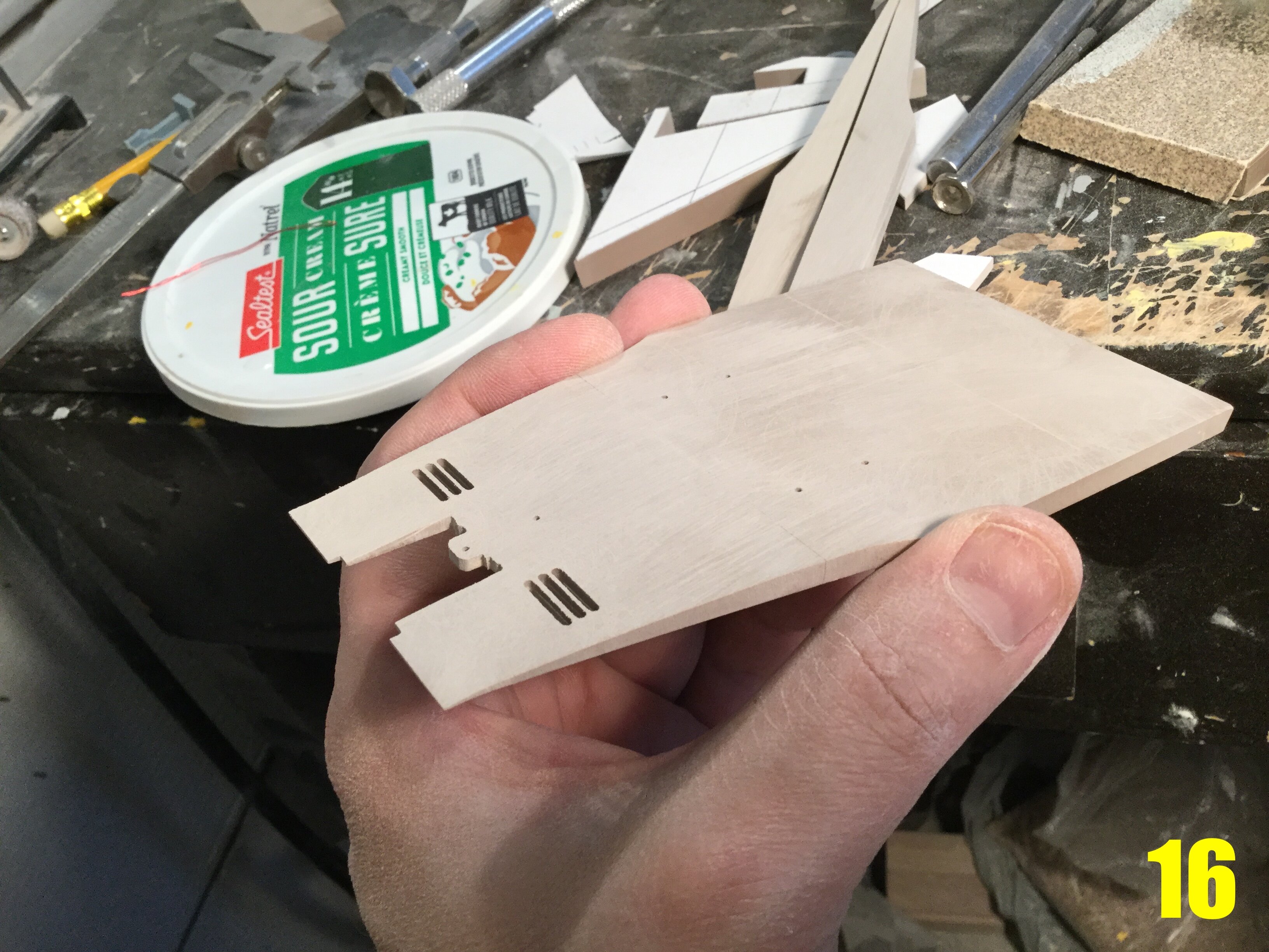
Pic 16: the fruits of my labor have paid off. More shaping and surfacing ahead, but it’s coming along nicely.
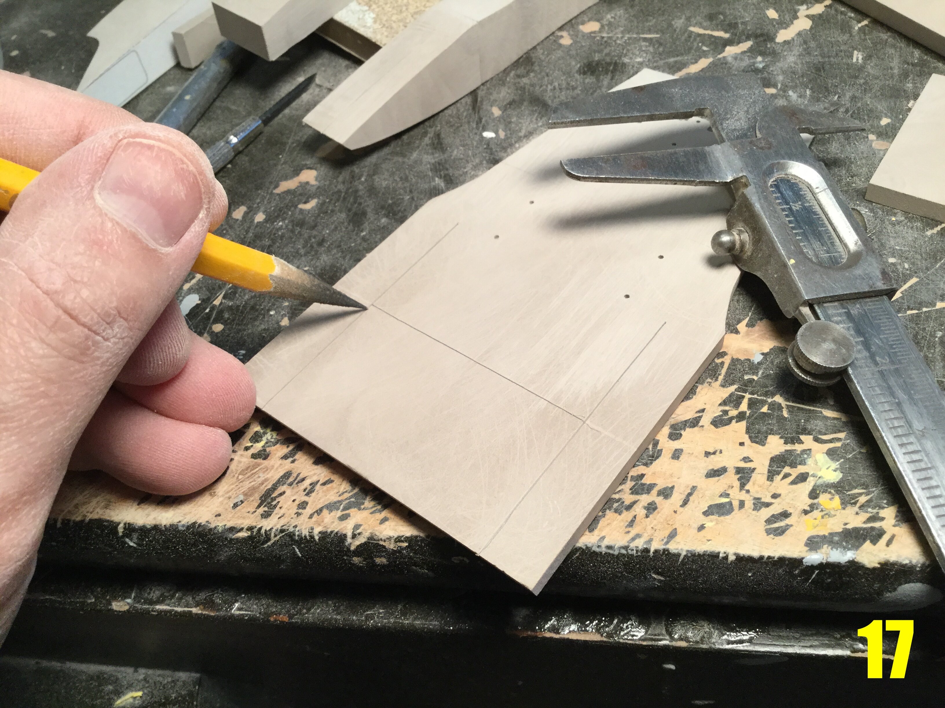
Pic 17: once the front end of the part is shaped, I now move toward the rear. Here, I’m tracing some guide lines for the downward slope I will create on the trailing edge, as well as the sides of the fuselage where the wings will join. As opposed to just having a flat, lifeless plane for the upper fuselage, I want it to have some subtle character.
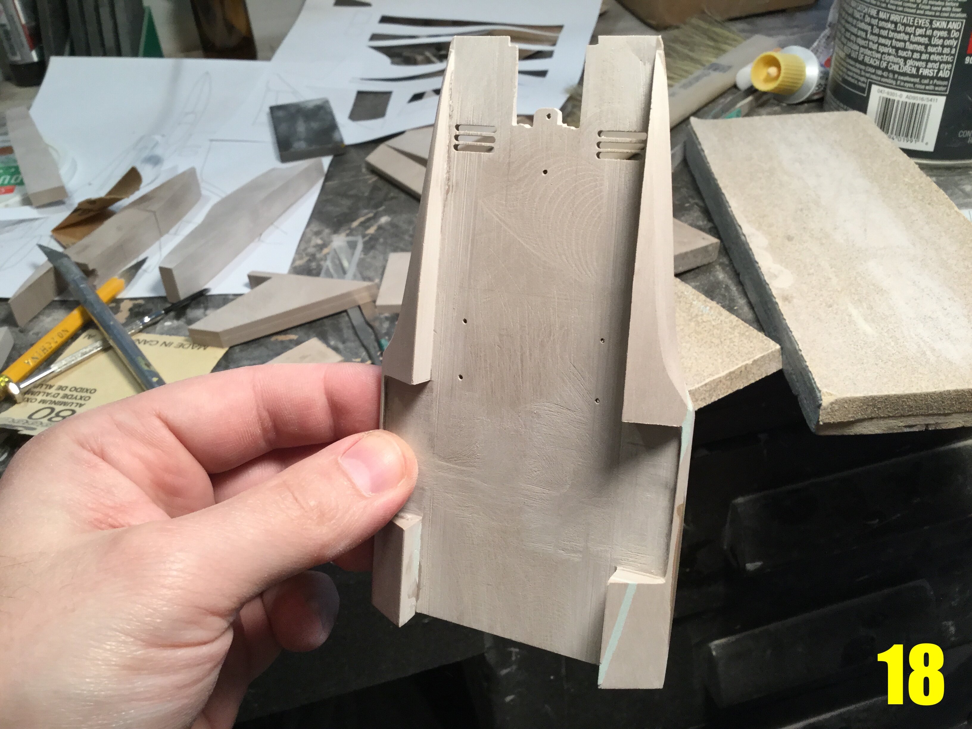
Pic 18: another delicate operation involves mounting part of the lower surface that blends the fuselage to the intake trunks. The two rectangular openings are the main gear bays. The frontal section will house the the cannons & fuel, while the aft sections are ideal for sensors, chaff & flares.
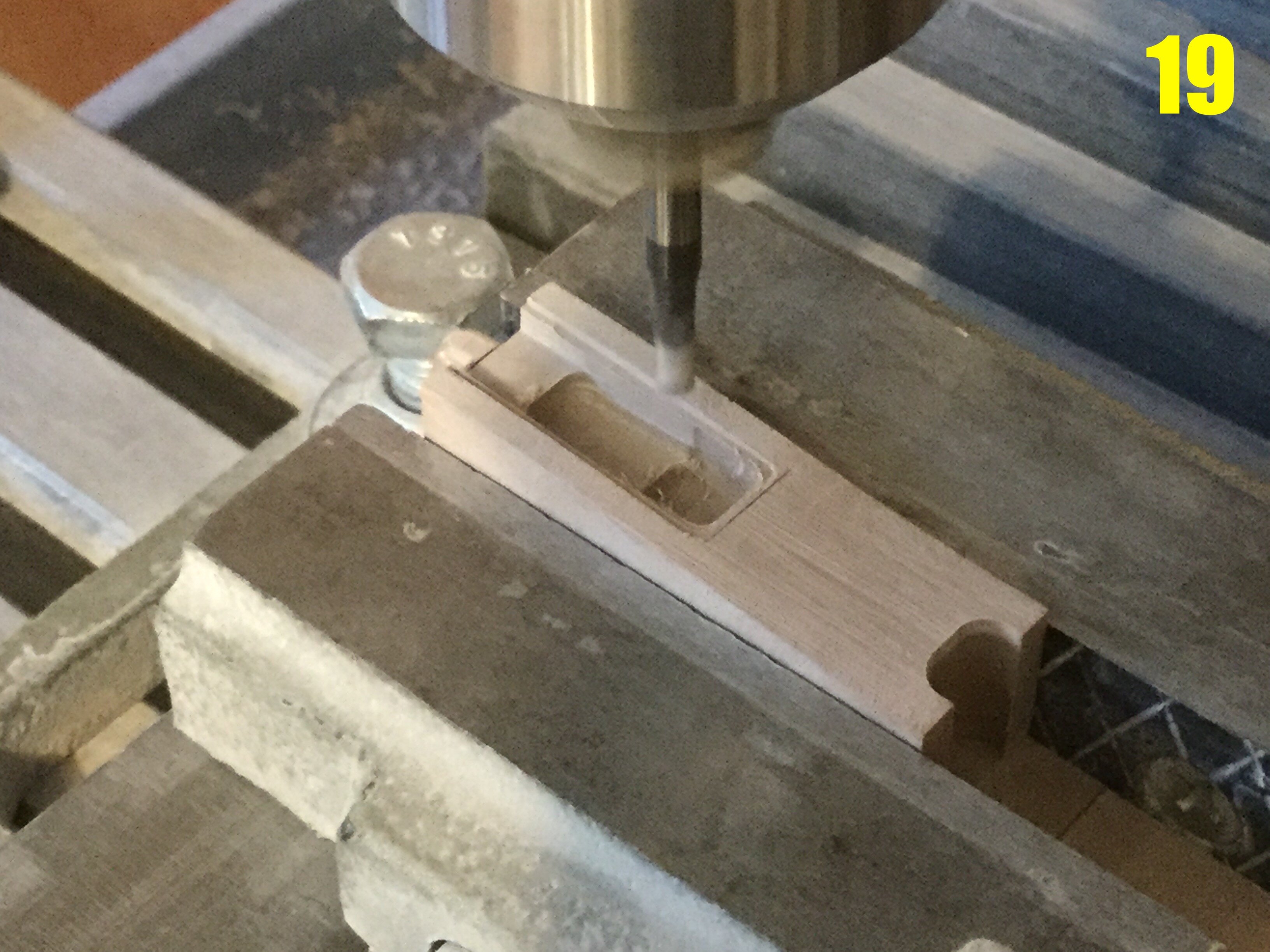
19: this is the underside of the forward fuselage/nose section getting its nose gear well machined. Out of necessity, the front bay will only be as deep as is needed to store the nosewheel assembly.
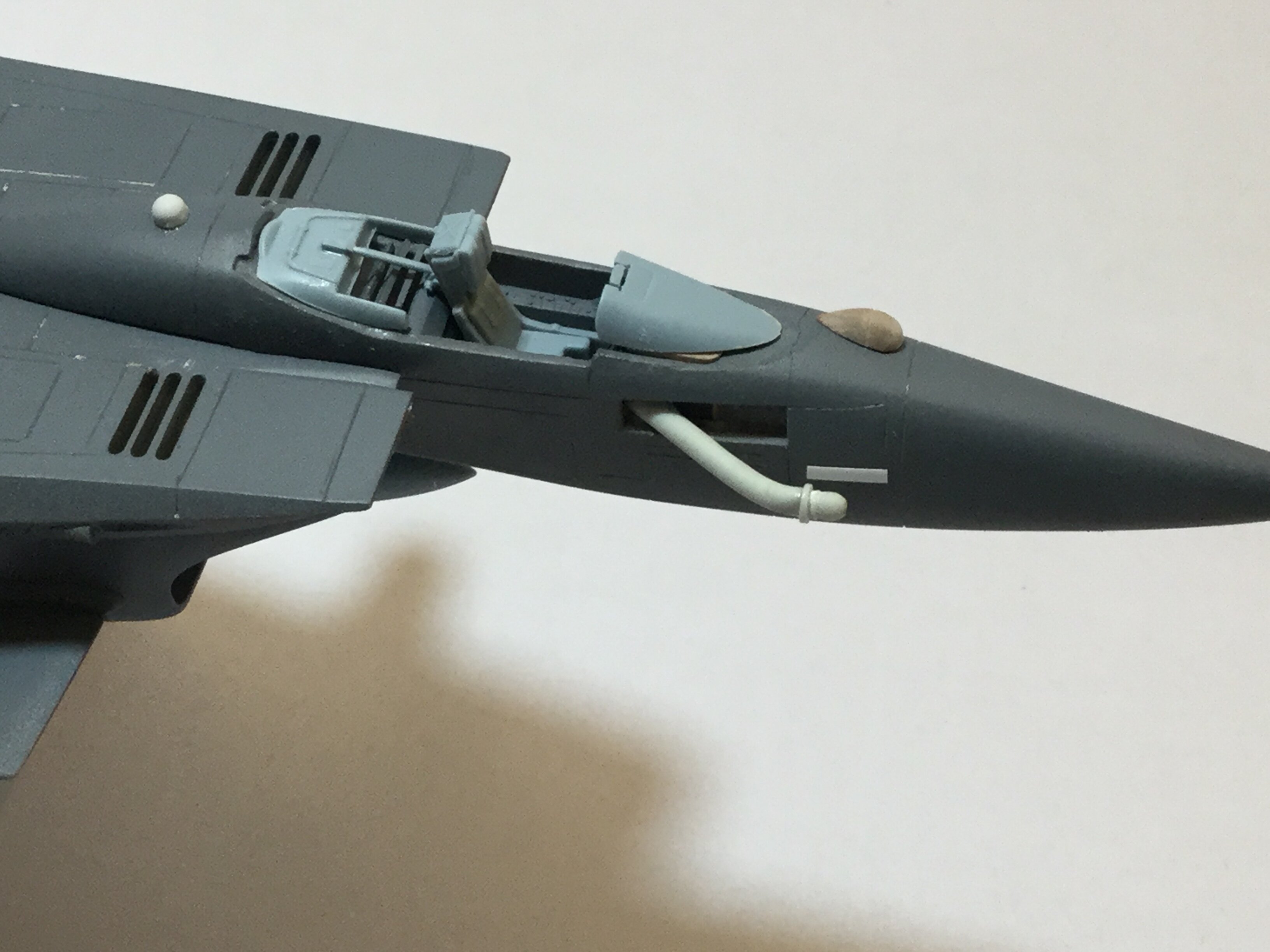
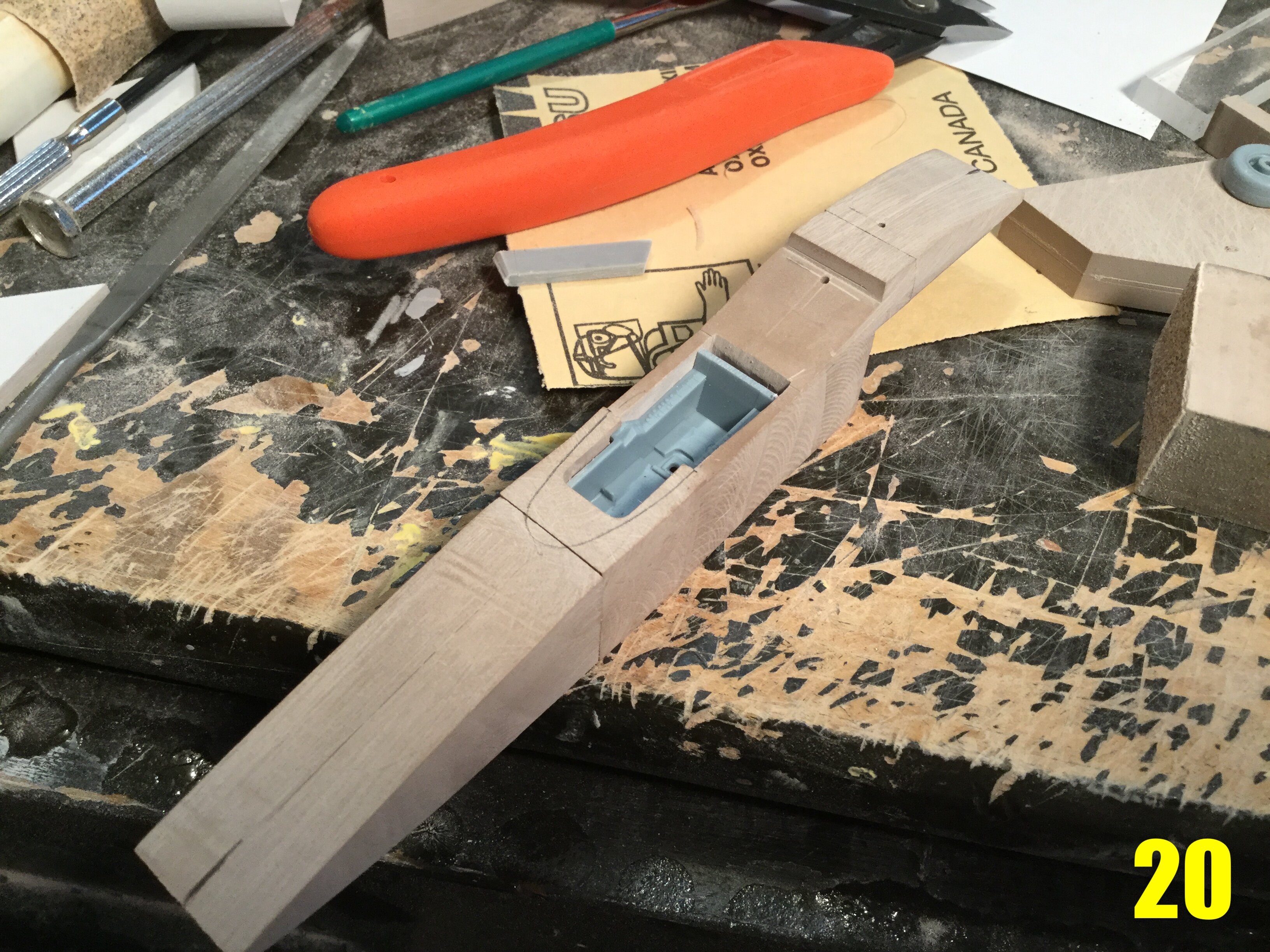
Pic 20: the same forward fuselage, now mated to the nose cone, and having recently been milled to accept a cockpit tub, courtesy of an Academy Hornet kit. The tub had to be modified and cut down to meet my requirements, but it now fits nicely.
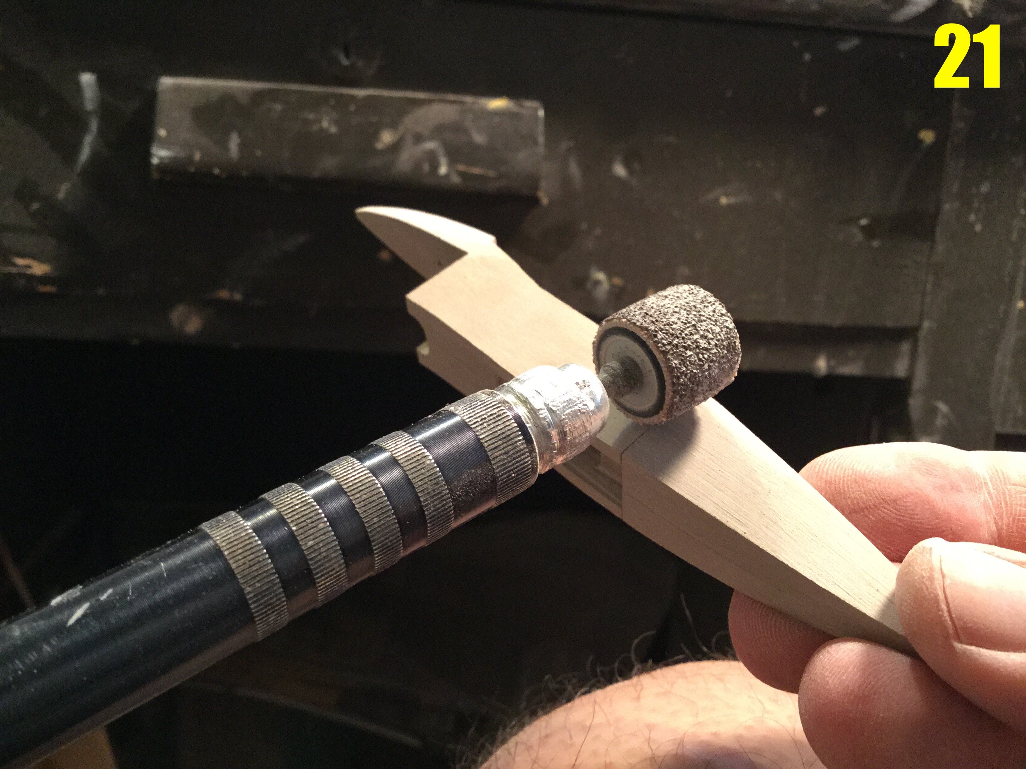
Pic 21: once all the critical openings have been milled, I can now proceed to giving the nose its more characteristicaly rounded shape, courtesy of my rotary tool. While some reference points were marked in pencil, I mostly just eyeball this part.
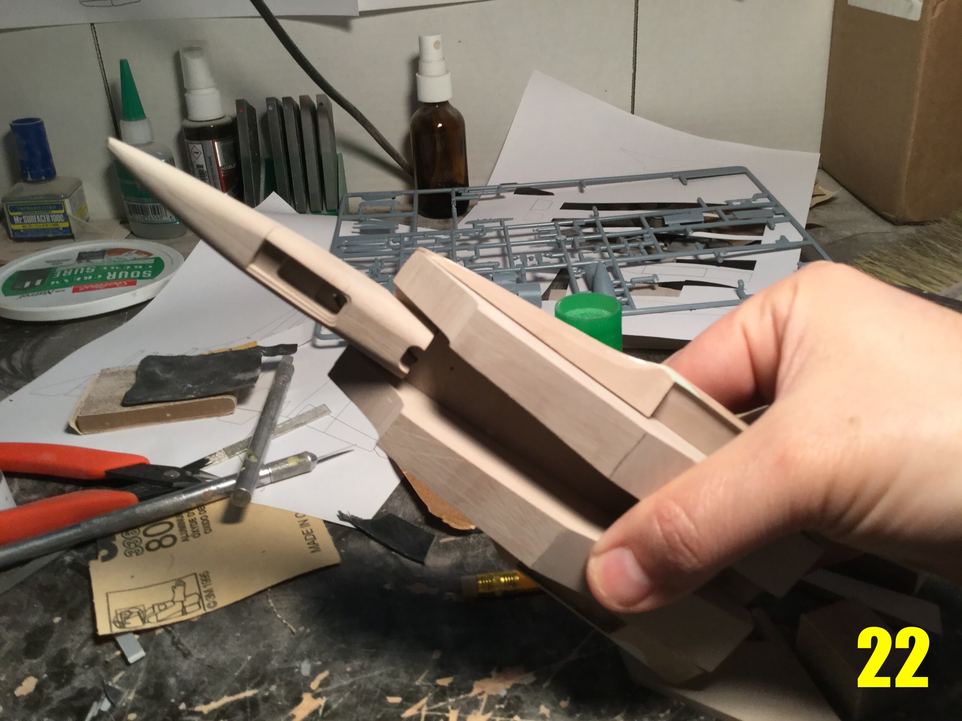
Pic 22: it’s starting to look like a fighter! The major fuselage sections are now cobbled together so that I can gauge the areas that need more love & refinement. It’s a wonderful blend of VF-1, F-14 and F-15!
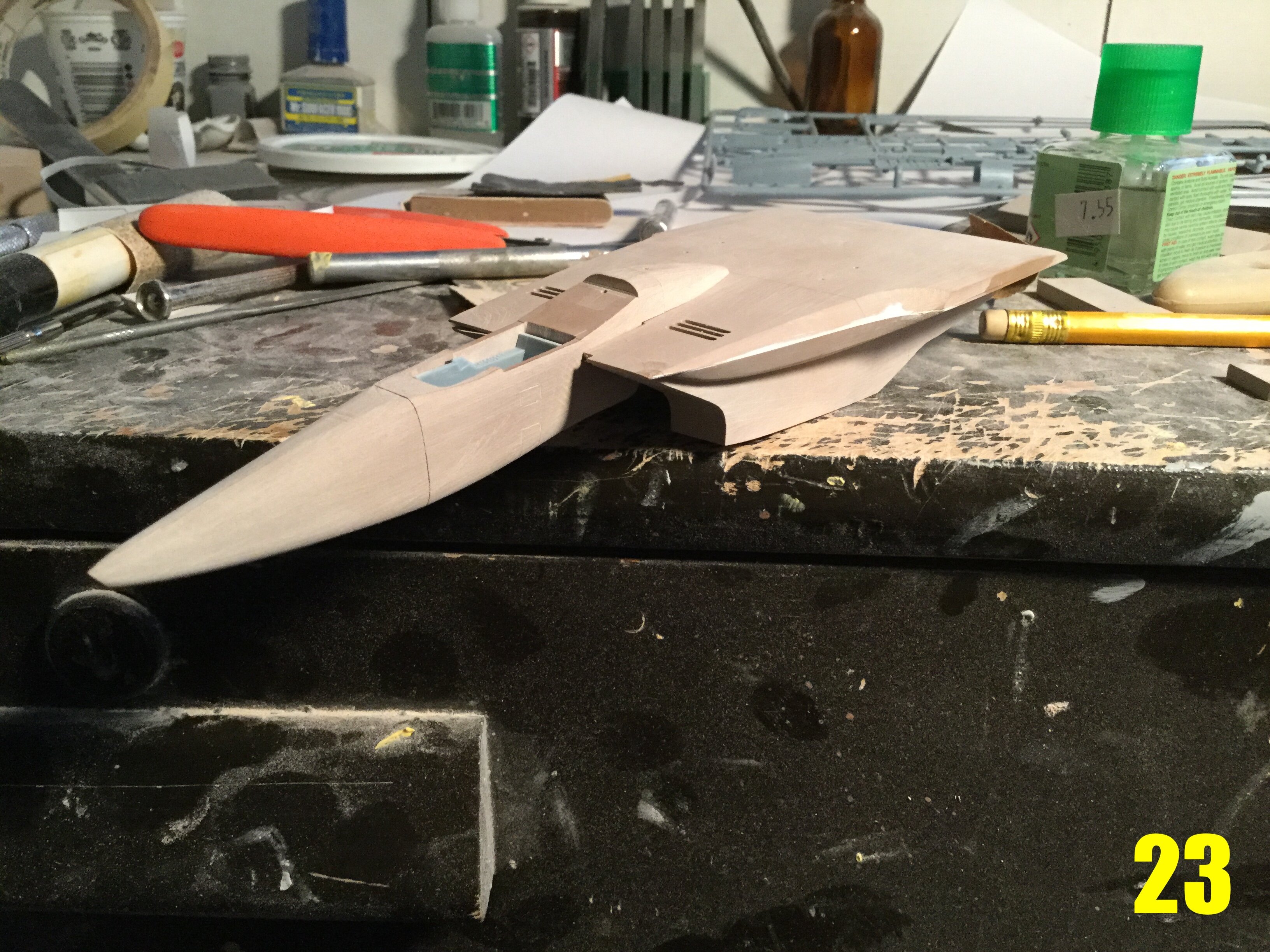
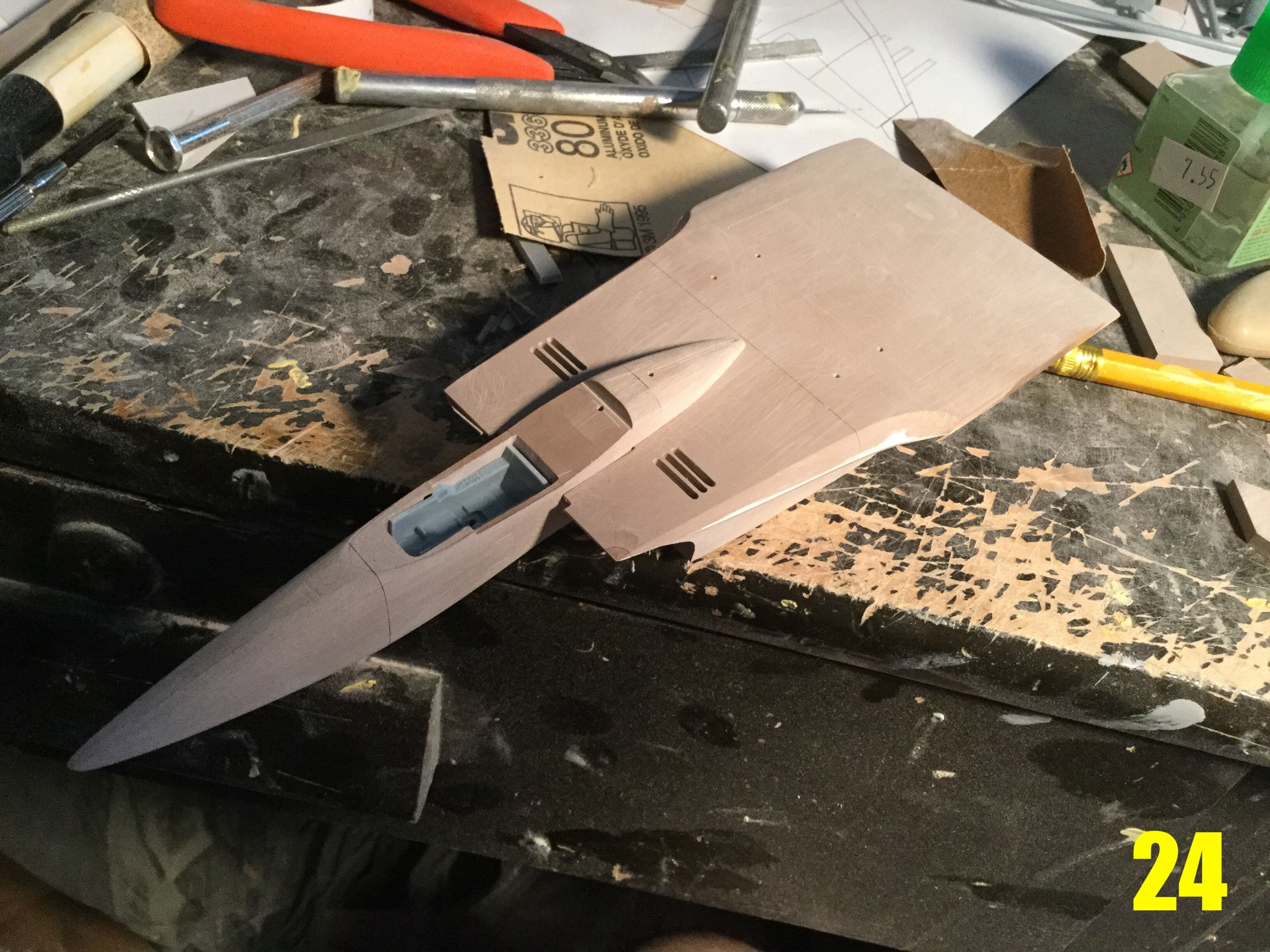
Pics 23 and 24: gone is the blocky nose, now sporting its signature curves. You can also see the angled pathway I created on the leading edge extension to give the aircraft a few extra low-observable features. This is turning into such a fun project, and it’s a wonderful change from the blocky shapes I’m used to. Tune in next week for another update, where I give some love to the control surfaces and the engine tunnels!
-
** PRE-ORDER WINDOW SLAMS SHUT**
-
15 minutes ago, pengbuzz said:
On the topic of Zentraedi craft, I found this pic online that shows the pilot inside their respective craft (probably been posted here before, but I figured it couldn't hurt to repost it if that's the case):
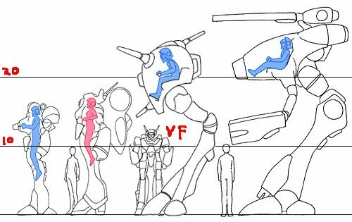
If you want a proper size comparison of Zentraedi mecha, look at the resin models I've made over the years. They were all designed to accomodate a proper Zentraedi soldier while remaining faithful to the visuals of the line-art. So far, every other manufacturer has failed in that respect.
-
9 minutes ago, Thom said:
Would you mind if I posted this on Starship Modeler?
Be my guest!
-
Captain’s Log: Thursday, June 2, 2020
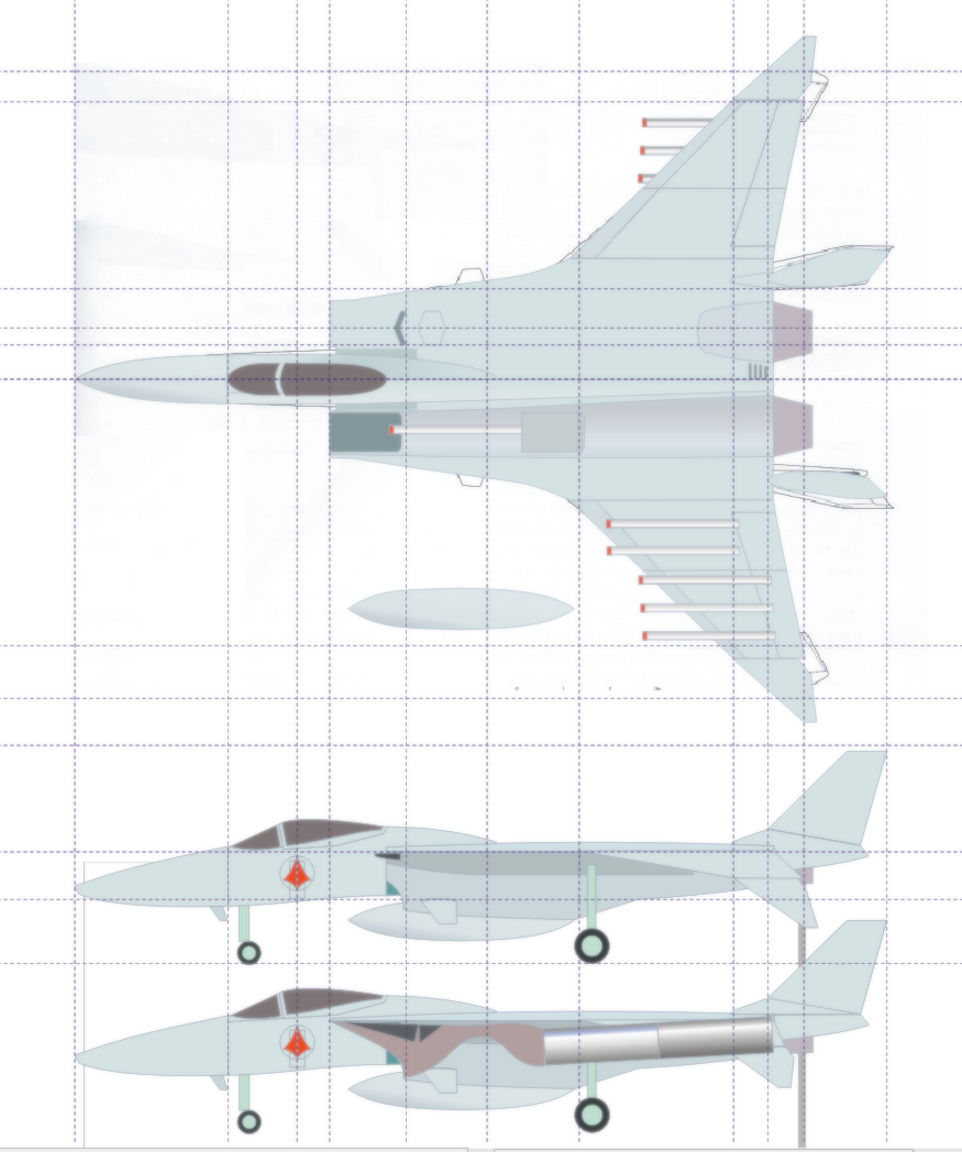
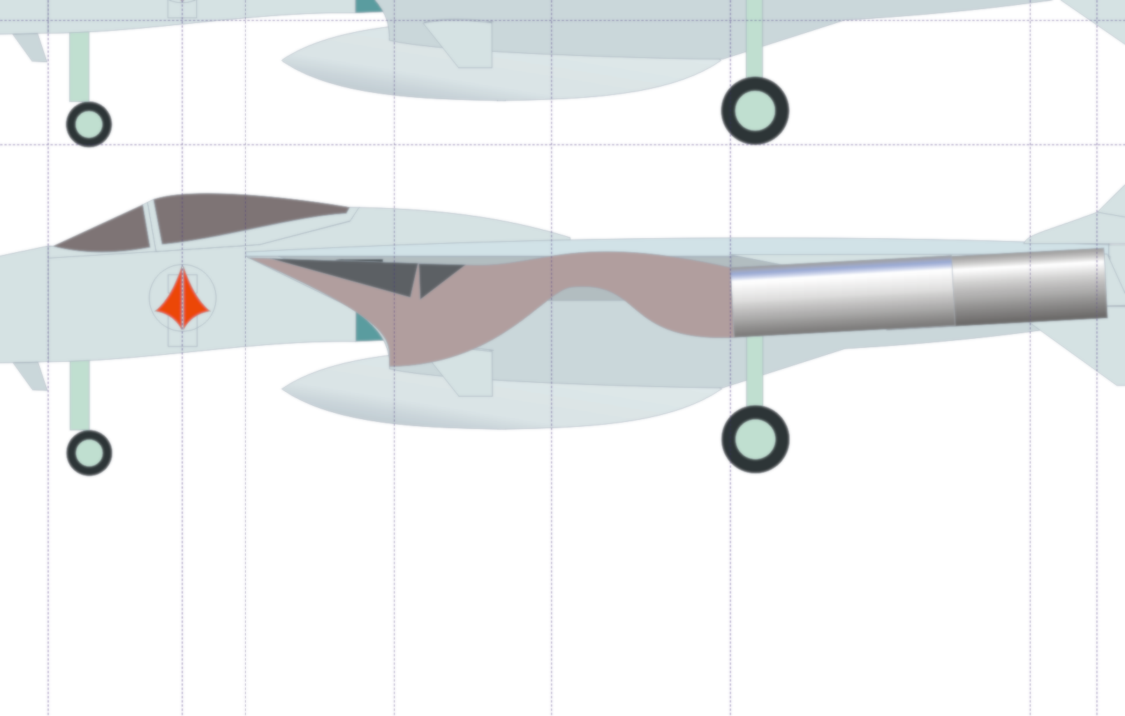
It has begun! Before I get into the actual construction process, I’d like to take you through the design process for the Dragunn, or more specifically, how I tweaked this otherwise throw-away design to give it a better sense of realism. Pic 01 shows the plan and side views that I’ll be proceeding from. You may not be able to tell, but the plan view I drafted is overlaid on a technical drawing that a customer sent me: a scan from a Macross aircraft book, the name of which escapes me. What’s interesting is that I had already begun my own drawings, and despite merely eyeballing the line-art, the two drawings were surprisingly close.
I intentionally made the wingspan a bit wider and relaxed the wing sweep slightly, figuring this would offer better low speed handling (needed for carrier landings), as well as move the CG slightly forward. The wings are reclined almost abnormally in the « official » drawing, which would create balance issues with the model having too much weight aft of the main gear. The two designs are identical in length, though I made the exhaust nozzles a bit shorter, which looks more like the line-art to my eyes. I don’t know if there was an actual sto-wing feature on the original, but I added one, so that will be a build option.
In addition to the three hard-points on each outer wing, I added a double launch rail for short range missiles closer inboard on the wing, as well as a hard point beneath each engine nacelle. In all, the Dragunn can carry 12 missiles, which is the same as the VF-1 payload: two triple-missle pylons on each wing. The fighter would also be able to carry a centerline drop tank if needed. I gave the Dragunn generous flaps to compensate for the lack of horizontal tailplanes, and these will give you the option to pose them in-flight, or drooped when parked. Moving on to the vertical tails, I decided to make these all-flying control surfaces: this was nessary to keep the V-tails from extending too high (hangar clearance issues) and also gives the Dragunn YF-23 style airbraking, making the need for a dedicated airbrake structure obsolete.
In pic 02, we have a cut-away of the intake pathway to the engine. Since this aircraft would have been designed in the 80s or early 90s, it would have likely attempted to integrate some low-observable features, so I designed the intake path F-22 style so as to obscure the compressor face and reduce the overall RCS. What’s interesting about this design is that it still allows for movable ramps to manage airflow. In fact, I will design the plane with auxiliary intake doors on the upper fuselage, Mig 29-style. It would have been easier to create a straight intake to the compressor face, but where’s the fun in that? But enough about details, let’s get on with the build.
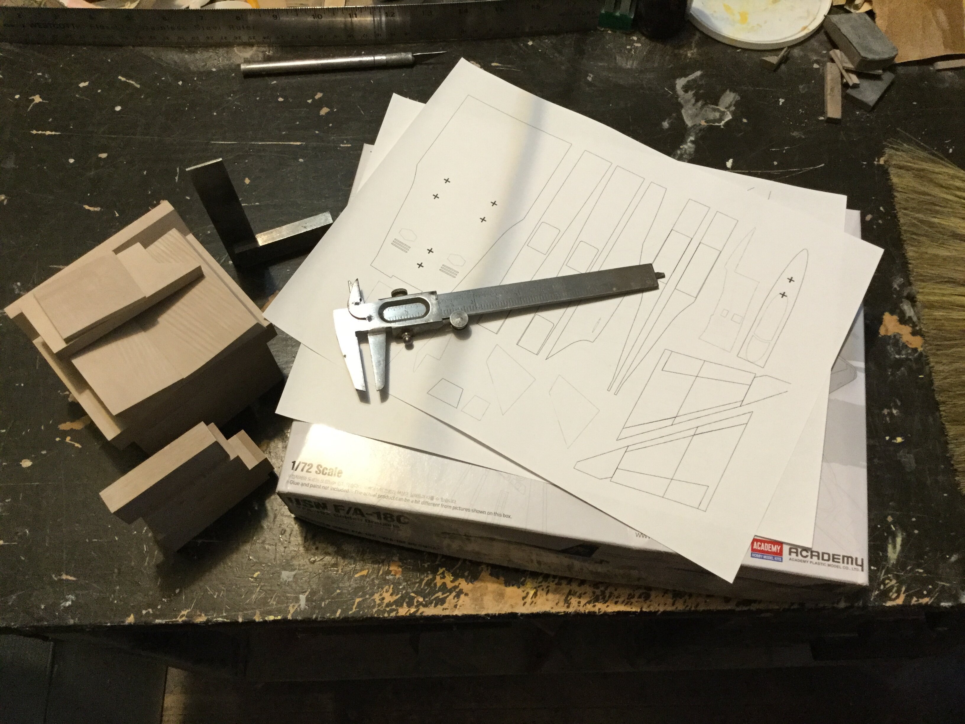
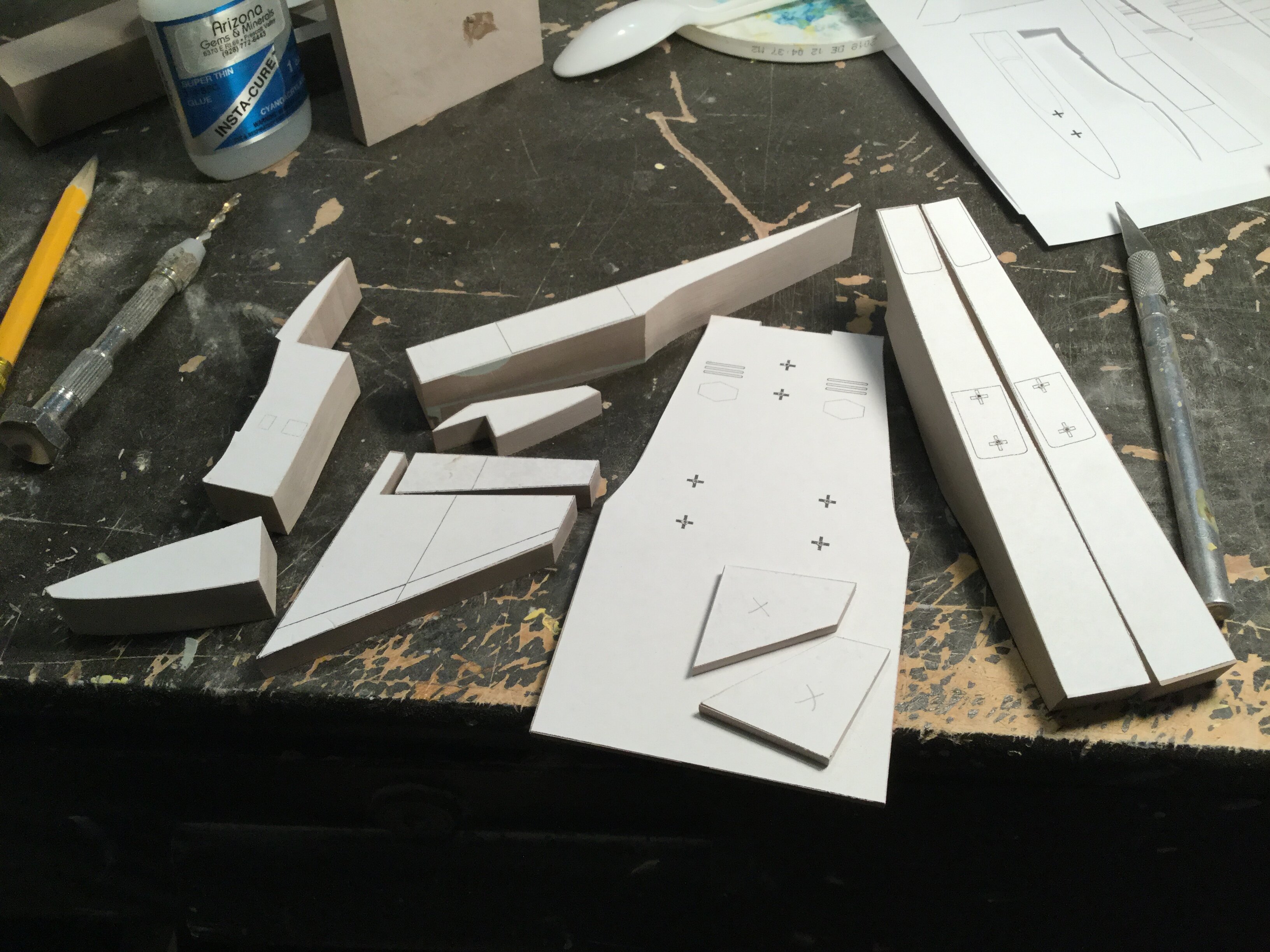
Pic 03: technical drawings are printed, tools and building materials are gathered. You’ll notice the box for an Academy F-18C under the plots: this will serve as a donor kit for certain parts to make the build more efficient.
Pic 04: plots are carefully cut and put aside. Sometimes I scribble extra info on these, depending on the nature of the part.
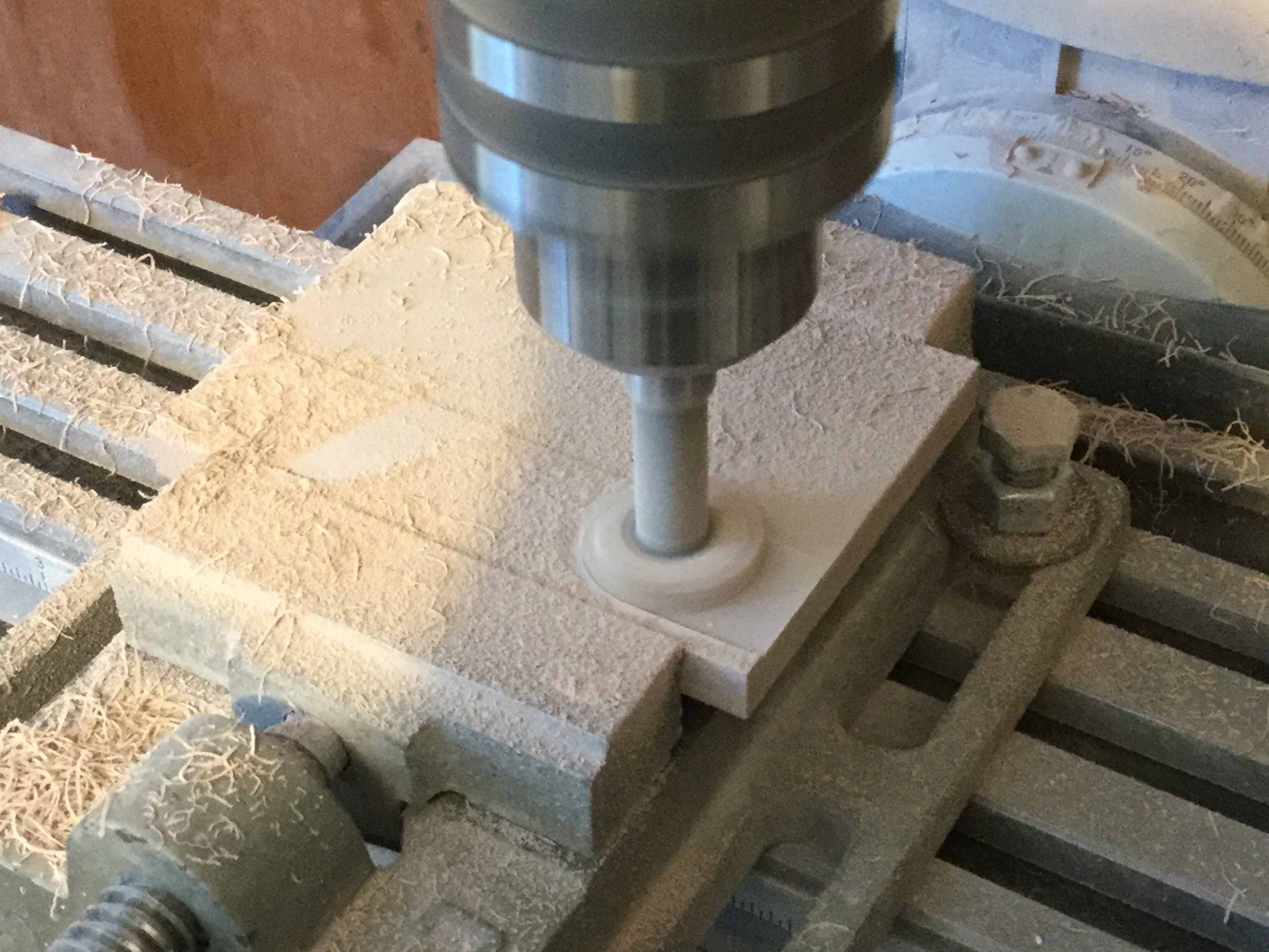
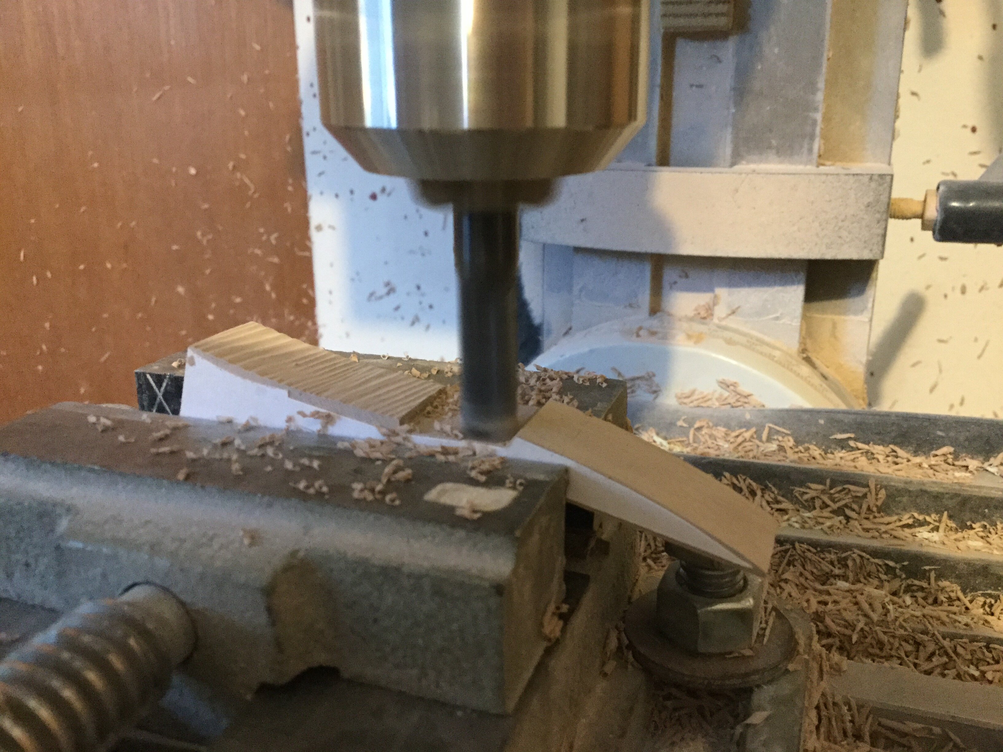
pic 05: the first order of business is to take some rough modelling board cuts and true them up with the mill. I’m using a face cutter tool for this operation to save time.
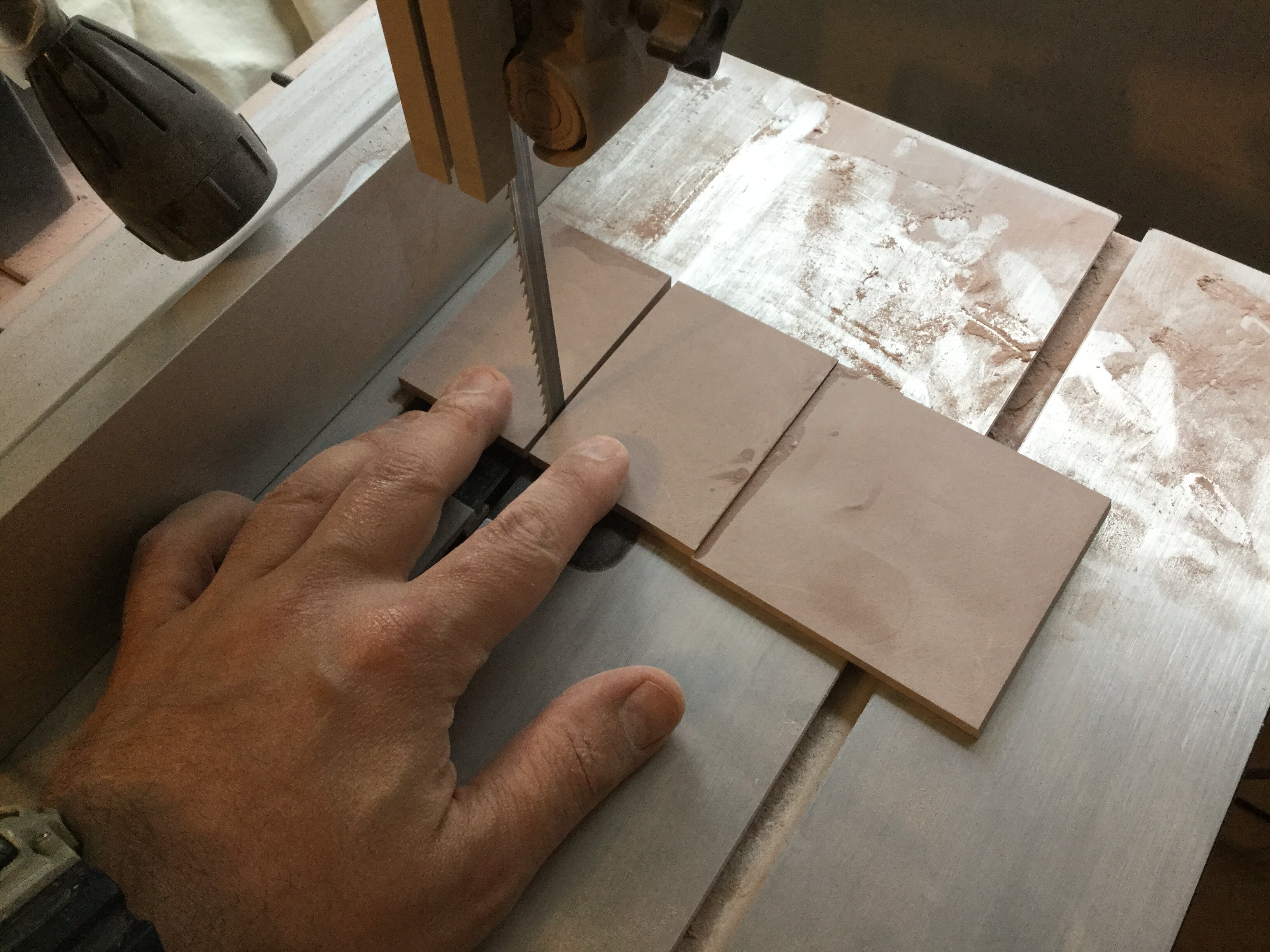
Pic 06: here I’ve glued a few pieces of modelling board together to make a larger part from which the upper fuselage will be made. I then trim the excess on the band saw.
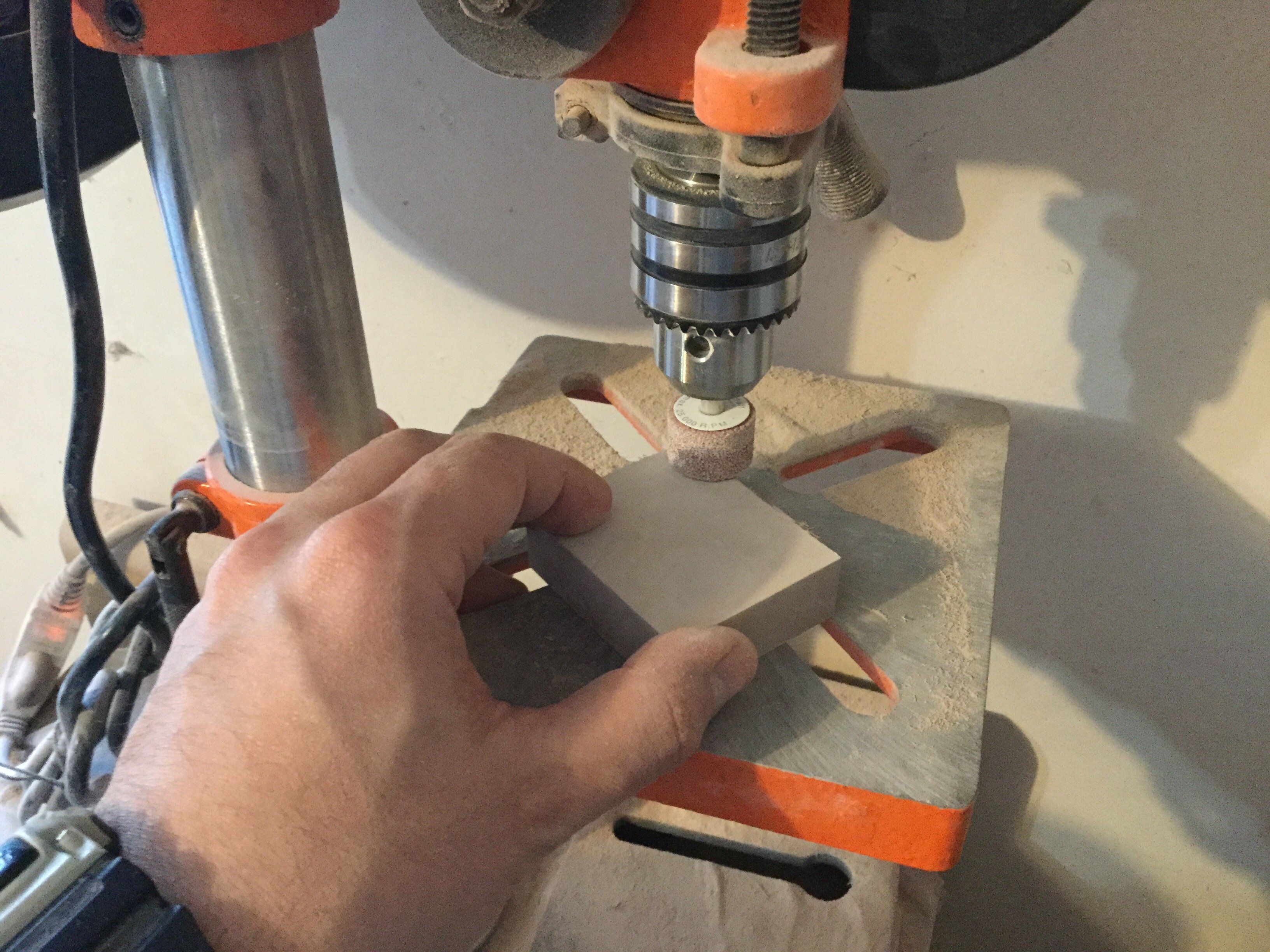
Pic 07: while I can make perfectly parallel blocks on the mill, sometimes I resort to the drill press and grinding stone, just because it offers a slightly finer finish.
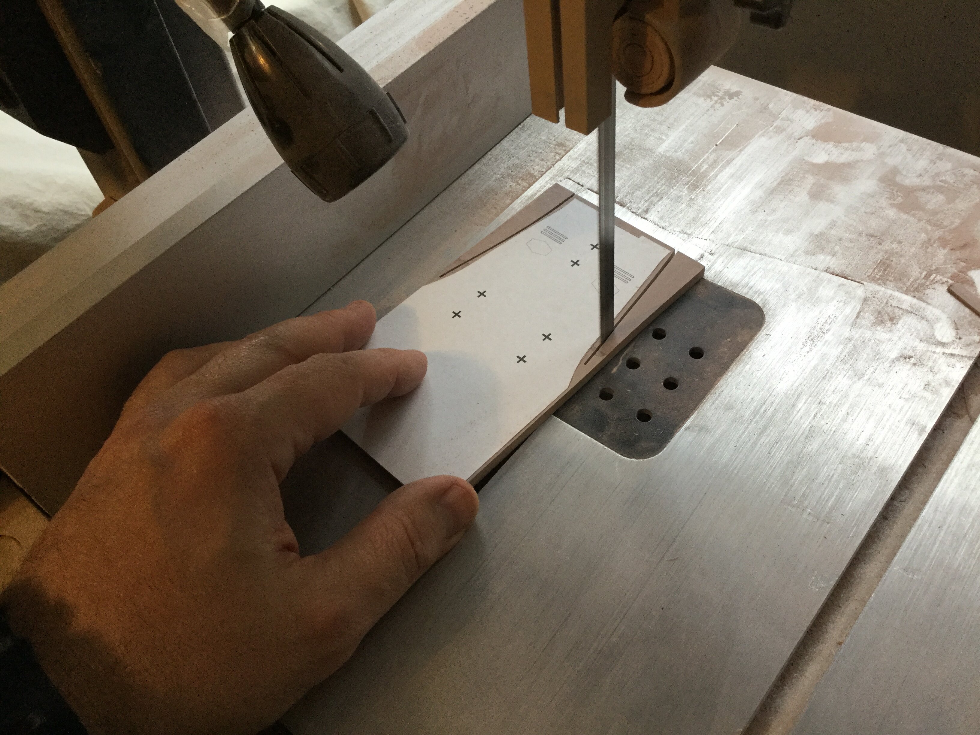
Pic 08: now that I’ve got some usable modelling board blanks, I can affix the templates and proceed to trim them on the band saw.
Pic 09: back to the mill. The part you see here will become the ventral intake trunks. I made both pieces from one block to better control the symmetrical profile.
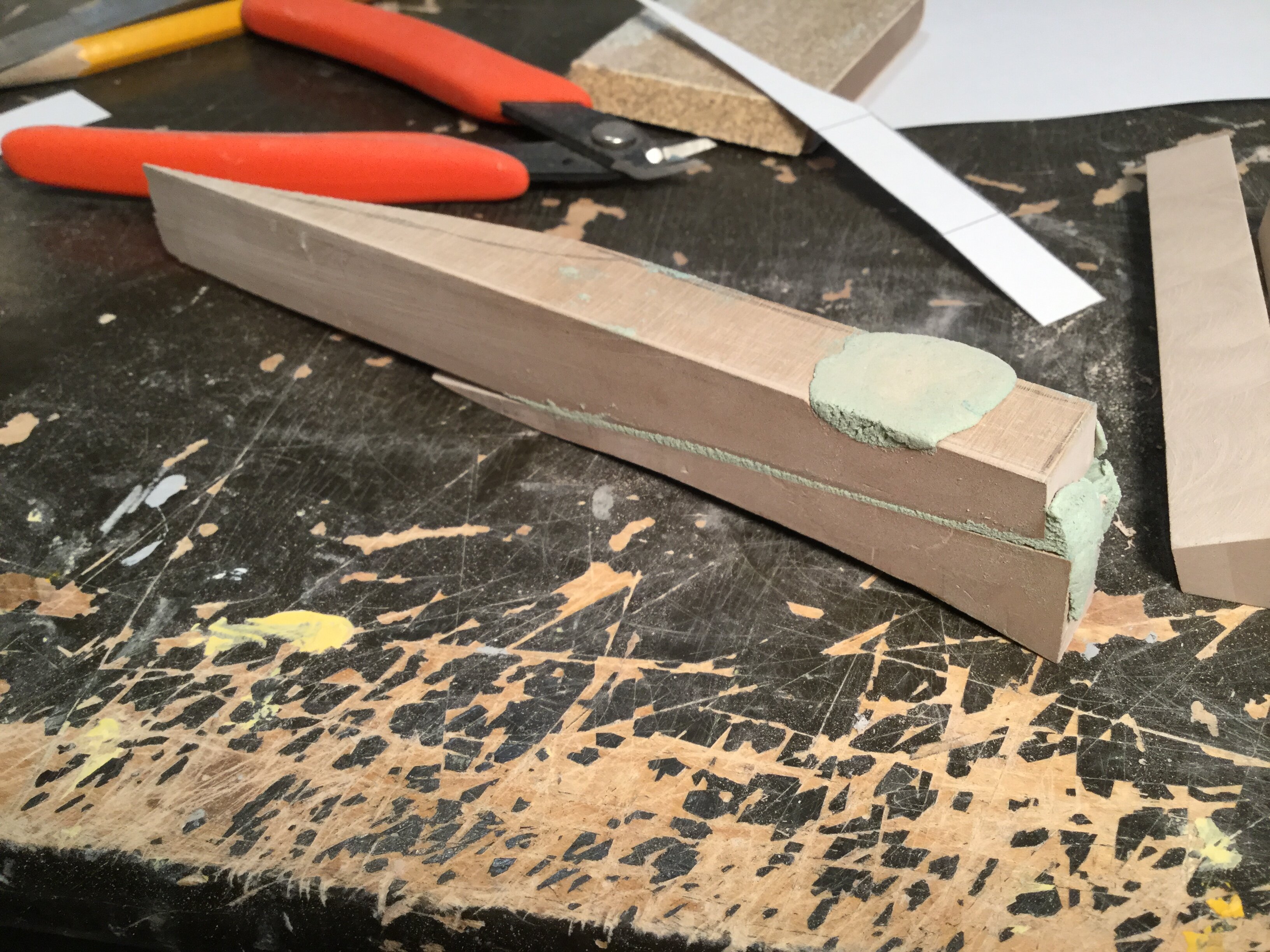
Pic 10: I have a lot of scrap pieces left over from other projects. Since no one part was adequate for my needs, I simply combined some parts and bonded them with putty to create something useful.
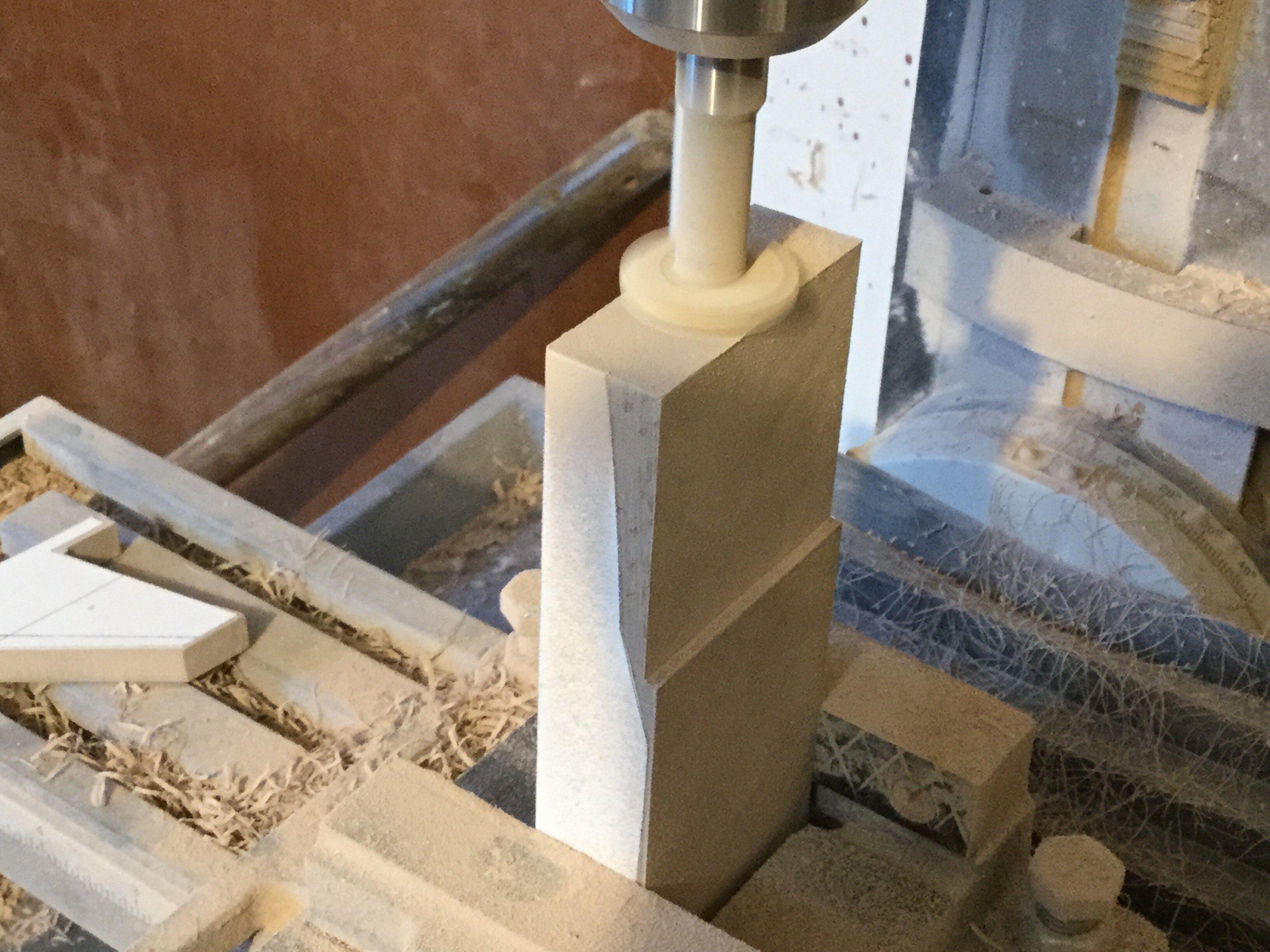
pic 11: here we see the forward fuselage being created. After just 15 minutes of machining, my table was completely covered in shavings and dust—and these aren’t particularly large parts!
Pic 12: now we’re getting somewhere! Most of the basic fuselage shapes are blocked out, and while this is the tedious part of the build, this is also where the model’s accuracy and geometry are set, so I take the time to make sure it’s done right. Next week, we get into the fun stuff, so stay tuned!

-
7 spots remaining.
-
MW member Valkyrie, please check your PMs.
-
2 hours ago, Sildani said:
Quick question: could you design the landing gear in a “cartridge” form, so that extended landing gear could be slotted into place and replaced with closed doors as desired?
That's pricisely what I was thinking for the landing gear, since I know how frustrating it is to fiddle with little closed gear bay doors. It'll be as plug-&-play as I can make it for sturdiness' sake.
-
Captain’s log: Monday, May 23rd.
I start taking payments for the 1/72 F-203B Dragunn today, please read the instructions carefully before you send in your payments.
FOR THE FIRST 30 KITS ONLY
Kit price only: $195 CAD
(One) Kit W/shipping: $234 CAD*
(Two) kits W/shipping: $457 CAD*
*Prices apply to Canadian and US destinations only. For overseas customers, you may place your order with Return2KitForm.
**Please note that the kit price jumps to $210 CAD + shipping for the second run.**
Payment instructions
Paypal: please use the Friends & Family option when sending payents via Paypal from now on. I’ve been offering kits for almost 18 years: if I had wanted to defraud people, I would have done it by now! Please just put « DRAGUNN » in the message, nothing else. I will know the quantity of kit(s) in your order from the amount you send.
Also, please make sure that your full name, shipping address AND phone number are displayed in your Paypal info, otherwise send it to me via PM.
Bitcoin: I accept payment via this method as well. I will calculate the amount to send in BTC when you’re ready to make payment, and it should be about $10 cheaper overall compared to Paypal. For this method of payment, also PM me.
As I’m sure you’re already aware, the technical drawing for the kit has already begun, and barring any unforeseen events, I will start fabrication on Friday the 27th of May. Aaaand we’re off!
-
5 hours ago, Chronocidal said:
Also a thought on the gear, if you aren't attached to the F-18 style. With a thick-enough wing root, you could probably pull off something roughly similar to the YF-21's gear, pulling back and slightly outboard of the engines at a slight angle, something like a more-vertical F-16 main gear.
A bent F-18 style strut might work, but I think it would need to rotate in the opposite direction to get out of the way of the underside thrust vents, extending back along the sides. Obviously you don't have to make it actually retract, but designing a bay to match that sort of strut sounds like a mess.
I was actually looking at the YF-21 main gear struts as being ideal. I'm officially putting out a call for anyone who has these pieces they'd be willing to part with, please PM me.
-
27 minutes ago, Knight26 said:
Given the lack of reference material, I doubt anyone will take issue if you take some creative liberties with the design to make it more "realistic" as it was a pretty throwaway design when you think about it.
In a sense, it's precisely with these types of subjects that I can do some of my best work. With the Buster (Legioss) and the Kaa-T'Sai (Cat's eye) I pretty much threw everything out except the general shape, and made a whole new vehicle that's much more consistent with how aircraft actually work. I also tweaked the shape of the Dragunn a bit today: wingspan has been increased a tad, and the nose was altered to look more like that of the VF-1.
-
Captain’s preliminary renderings: May 19, 2022.
I’ve begun laying down some Dragunn diagrams, trying to make sense of what I see in the line-art. For one, while it’s an interesting overall shape, the details weren’t terribly well thought-out: the 3 missiles on each wing are mounted where the wing chord itself is drastically reduced, and no apparent pylons are used, which would interfere with the motion of the flaps. Also, 6 missiles seems a bit inadequate for a modern fighter, so I’ll look into adding at least an additional hard point inboard of the sto-wing mechanism.
Also, it looks like they « kinda copied » the look of the F/A-18’s main gear, but decided to hinge them into the wing root… F%$#&*(@#(&?!!!! Seriously, do these « designers » even know how to think critically?? It’s fine. It’s fine. We’re all fine here, thank you. How are you?
On the up side, I may be able to give this thing some unusually good airbreaking capability, and that (mostly) flat upper fuselage is an ideal surface for fine panel lines and access hatches. If the drafting goes well, I may be able to start construction next week, so stay tuned!
-
Looks like this project will be going ahead--woo-hoo!! More information to come next week, so stay tuned.
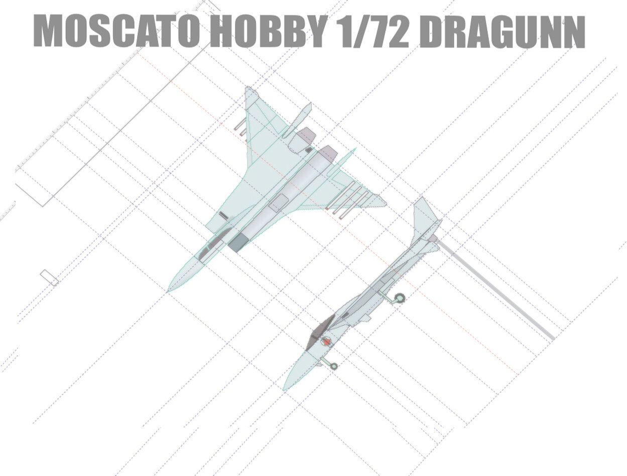
1/72 F203 Dragon II Kit Proposal --Moscato Hobby
in Model kits
Posted
Captain's Log: Tuedsay, July 26th. 1/72 F-203B Dragunn resin kit scratchbuild update.
Supply shortages are a frustrating matter! I just received my mold material yestarday, so I'll be able to complete the remaining molds... Now waiting on my resin shipment. Thankfully, I should be able to get through most of the production run with the resin I have on hand. All the tiny parts which were a concern for me have been casting very well. The clear canopies are underway as well, and looking extremely good right out of the mold. I'm also working on the markings for the fighter, which I may simply offer as free artwork that you can download & print yourself. It will also include a color & markings placement guide.