wwwmwww
-
Posts
1275 -
Joined
-
Last visited
Content Type
Profiles
Forums
Events
Gallery
Everything posted by wwwmwww
-
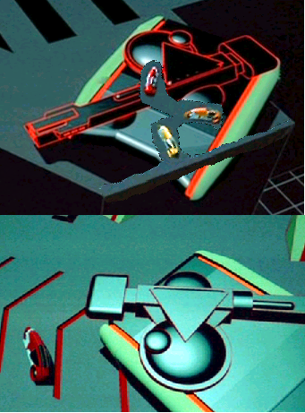
Ok... using the pics I was pointed to here: Tank on ledge Light cycles on same ledge Ram's cycle right next to a tank I made this pic. If you ask me they aren't consistant within the movie about the scale on these models. The cycle looks twice as large in the second picture as it did in the top picture. Is anyone aware of any official or unofficial specs for these models? Thanks, Carl
-
Here this picture should answer both the what and the why that I posed yesterday. Enjoy, Carl

-
Just to show you what a difference saving a picture as a jpeg can make here is the PNG version of my teaser pic. Enjoy... Carl

-
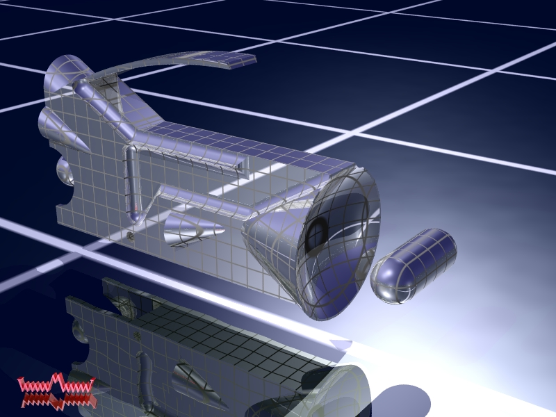
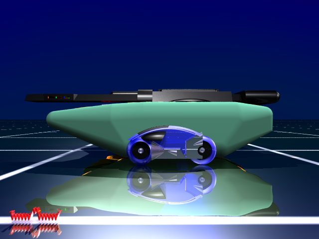
Well I've now got the TRON DVD and been going over it frame by frame to pull out as many details as I can. And while doing so I slowed down to catch the Trivia/Bloopers talked about here: http://www.tron-movie.com/trivia/index.htm And I now have a few I think could be added to that last: (1) The scene from 5:25 to 5:30, Clu's tank is missing a part. Can anyone tell we what part it is? And note Clu's tank has this part in all its other shots so its not just missing because its that one tank. Here is the interesting part... soon I'll be able to show you WHY its missing. (2) See the site above about the person hiding in the computer room. Well... he's NOT the only one in there. In the scene from 26:44 to 26:45 the camera pans past a very reflective piece of computer equipment. Watch that reflection... it gives you a very nice pan of the whole film crew. Has this been spotted before? I find it hard to believe I'm the first to notice it but I couldn't find any other mention of it on line. (3) Check out the tank in the scene from 49:52 to 49:55. Its also different from all the other tanks seen in the movie. Can anyone tell me what is different about it? I don't think this could be called a blooper as maybe its just a unique tank. (4) In the scene from 51:11 to 51:12 I find the double shadow of the tank rather interesting. Note the tank isn't the only thing to get a double shadow in the scene. As from 51:15 to 51:16 you can see the light cycles themselves also have double shadows. And finally... here is my first public showing of my TRON tank. Its in the PNG format as I've seen just what jpegs can do to my pictures. Please compare it to this reference: And I've put a light cycle in there for reference. I'm making a guess there about scale. If anyone thinks I'm off please let me know. Enjoy fellow programs... Carl
-
Oh boy... the cycle was a cake walk compared to the tank which is taking me about 10 times longer to get 'right' then it took to get the cycle 'right'. Most of that being the lack of as good reference pictures however that's only part of it. The shape is much more complicated. As for the solar sailer I'm not aware of any really good reference pictures (front, side, top, bottom, rear views etc.) and on top of that I think its shape is even more complicated then the tanks as I'm not sure it can be built from POV-Ray primitives (spheres, boxes, cones, etc.) as the cycle and tank can. And besides I think the tank and cycles will be more fun to play with. I don't really see a solar sailer chasing around tanks or cycles as being all that plausible. I agree it might look nice in the background though... hmmm... that gives me an idea. And thanks.... Carl
-
Yes... the tank will have transluent parts. The reason the cycles above are not transluent is I was still working on the shape at that time and it takes alot longer to render if the shapes are transluent. For example "Anatomy of a Light Cycle 3 of 3" has been rendering for 4 days and its still only 28% done. However as the actual cycles weren't transluent I find your comment a little odd. The transluency was a little artistic licence on my part. Still thank you for the compliment... Carl
-
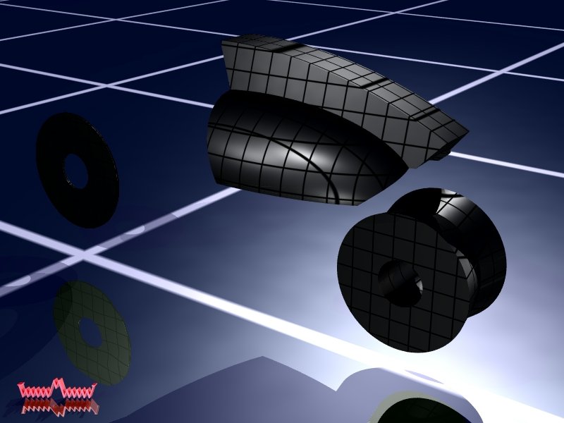
Here a a teaser pic of my next project. By the way... I've noticed that converting these to jpegs takes alot away from the image. If anyone wants the raw bit maps just let me know... Enjoy... Carl

-
Anatomy of a Light Cycle 2 of 3
-
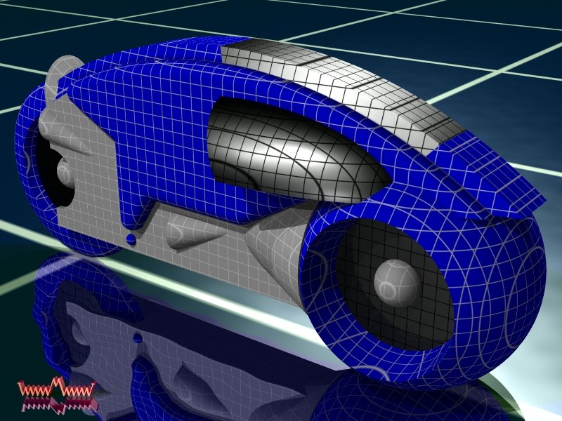
The next thing I wanted to share is a series of three pictures that I'll call "Anatomy of a Light Cycle". The last of which is still redering and I'll post it when its finisted but here are the first two. Anatomy of a Light Cycle 1 of 3
-
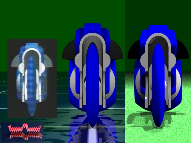
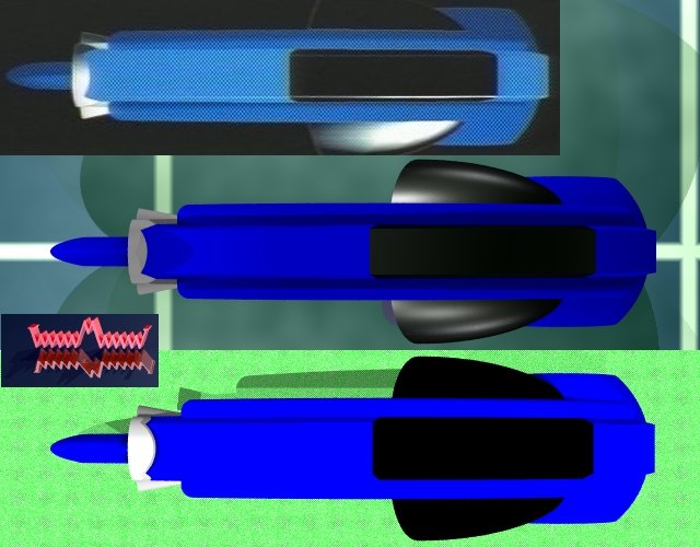
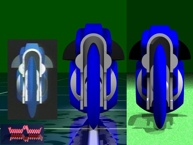
Here is a view from the top... Reference is on the top. First pass is on the bottom. And the second pass is in the middle again. These are the main reference pictures I used to make the model. In many cases I resorted to counting pixels to get mesurements to input into POV-Ray. Enjoy...
-
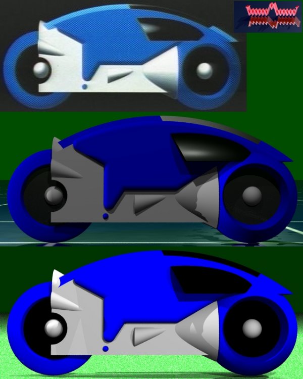
Here is a view from the side... Reference is on the top. First pass is on the bottom. And the second pass is in the middle.
-
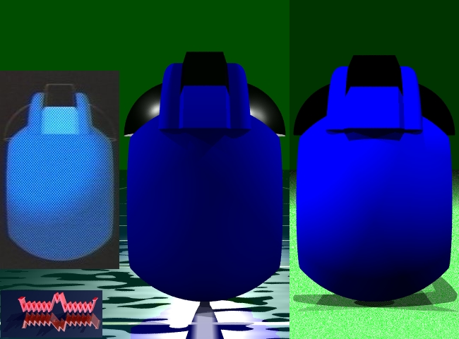
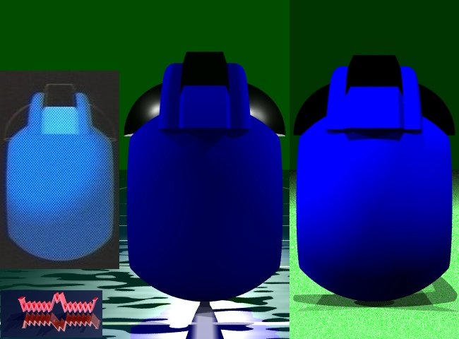
Here is a view from the front... Reference is on the left. First pass is on the right. And the second pass is in the middle again.
-
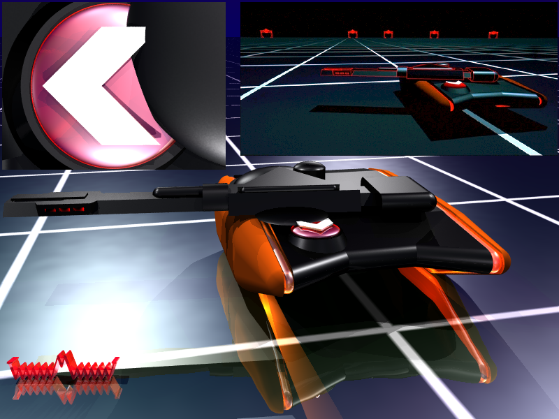
Its me again... I ended up aborting the last render I had going. At the rate it was going it looked like it would have taken a year to complete. Besides I wanted to start on my next project which I'll show you a taste of here shortly as a work-in-progress. But before then I wanted to go back to the beginning and start this thread properly. In my first shot I tried to be funny and posted here: http://www.macrossworld.com/mwf/index.php?...=3&t=1585&st=60 I never was very good at being funny... so I did a second pass on the model and posted here: http://www.macrossworld.com/mwf/index.php?...=ST&f=26&t=2865 However I think I scared most away by mentioning 'Math' and I think I derailed my own thread. So before I show you my new work-in-progress... Here are a few pics of my Light Cycle that show you how it developed. The cycle on the left is a reference picture that I used. The cycle on the right is my first pass at my model. You can see another picture of that model at the first thread above. The cycle in the middle is my second pass and I think I made a fair number of improvements. Can you spot the differences? And again you can see two more very nice pictures made using this model at the second thread above which I won't repost here for the sake of saving space. I'll use this tread to post any new pictures and if you want to talk math please post to the other thread. Comments, Suggestions, Questions, etc. are all welcome... Now on with the show, Carl
-
I'm back... interview went well I believe. I learned I was the first to be interviewed for the position and that they have plans to interview one or two others. They said they hope to make up their minds in two to four weeks. So needless to say I'm still sitting on pins and needles. I wish I had something better to say but atleast its not bad news either. Oh... and I believe I've now got a solution to my math problem. For those of you interested (if that's anyone) here is what I have at the moment. I still need to sit down with pencil and paper (alot of paper) and check this all out and find a way to code it... but I believe this is correct. First of all start by referencing this page: http://mathworld.wolfram.com/OblateSpheroid.html From there I went to Dr. Math and they sent me the following... Hi again, Carl. After thinking about your problem I decided to consult a colleague, who was able to provide some useful comments. To help clarify things I restated the problem as below. Whether or not these changes actually simplify the problem is open to debate, but I hope you are able to follow the reasoning: 1. Consider the oblate spheroid S that is the rear wheel. In order to have it rest on the ground, we must find the point Q on the spheroid at which a tangent plane intersects it. This set of tangent planes is parametrized by their height--we drop the wheel down onto the ground until it touches at one point Q(x,y,z). 2. To make use of this picture, we need to find the point Q as a function of lean angle. To make the math simpler, it is helpful to put the oblate spheroid S centered at the origin (although tilted with respect to the coordinate axes). This is a very helpful simplification. 3. Define the coordinate system as follows: Let {x,y,z} is a right handed coordinate system with z pointing up (that is, perpendicular to the ground). Define the angle of lean as theta = (pi/2 - v*), where v* is according to Eqs. (1)-(3) in the notation of the Mathworld [MW] site. That is, v*=0 corresponds to a tire that has fallen over on its side, and v*=80 degrees means that the tire is leaning by 10 degrees from upright [we will want to find the location of Q for a lean of approximately this size] Now, one question is what is the actual tilt value that we should use for a given theta. For small leans theta, we can let v = pi/2 - theta, and call it the "first-order" calculation. But for the general case, we will use the arbitrarily rotated ellipse [from Eqn (62), MW]. I think that the angle B* is v, and angle P* is chosen by rotating the bike frame about the center of S, so that the front wheel touches the ground at the same height as the bottommost point of S. This keeps the ground planes horizontal in the coordinate system (again, this is extremely helpful in keeping things tractable). Thus, at this point we have the equation of the rotated spheroid S: Ax^2 + By^2 + Cz^2 + Dxy + Exz + Fyz = 1 [62,MW] with coefficients given in terms of angles B* and P*, and the semimajor and semiminor axes lengths of S [Eqn's (63)-(68), MW]. Now, we want to find the horizontal plane z = z0 which intersects the bottommost point of this spheroid. How do we calculate this? The key is to realize that any plane that slices through S gives an ellipse. If this ellipse degenerates to a single point, we have found a tangent plane. For a horizontal plane at z = z0, we have Ax^2 + Dxy + By^2 + (E.z0)x + (F.z0)y = 1 - Cz0^2 This equation describes the intersection between S and the plane z=z0. A change of variables (FD - 2*BE) x = -----------z0 + X (4AB - D^2) (DE - 2*AF) y = -----------z0 + Y (4AB - D^2) leads to (if I didn't make a mistake): AX^2 + DXY + BY^2 = 1 - [C + (EDF - BE - AF)/(4AB - D^2)]z0^2 Now, if the right hand side is positive, we get an ellipse. If it is negative, there is no solution and the plane z=z0 does not even intersect S. And if the right hand side vanishes (yay!), we get an expression for the value of z0, in terms of the numbers A,B,C,D,E,F: z0 = sqrt(1/ [*]). where [*] represents the bracketed expression in the previous equation. Whew!! Now you're done: you have the twice-rotated oblate spheroid (rotations by B* and P*) centered at the origin (x=0,y=0,z=0), resting on a ground plane at z=-|z0| at the contact point Q(X=0,Y=0). Note that you'll have to shift coordinates back to find Q in terms of x and y. The rotation angle P* tells you how much to elevate the front wheel so that it too rests on the ground plane. Thanks for submitting such a fun problem. - Doctor Douglas, The Math Forum
-
I'm about to take off for an interview I have tomorrow. Wish me luck everyone. Maybe by the time I get back I'll have another render to share with y'all. Later, Carl
-
Does this qualify as a Max and Milia version? The render time for this one came to 1d 02h 40m 06s. And to be sure to give credit where credit is due. The wall in the background was made by maping the PNG images from the Armagetron Moviepack addon to a few boxes and sticking them together. You can get them here: http://armagetron.sourceforge.net/addons/moviepack.zip Everything else is my creation. At some point in time I might redo the wall with real floating 3D cutouts but for now I thought is was a good quick way to make a wall. I always welcome feedback and I may even try to honor a few requests... Enjoy everyone... Carl
-
Let me second that... Thanks guys. I got mine yesterday too.
-
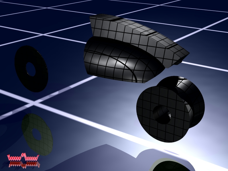
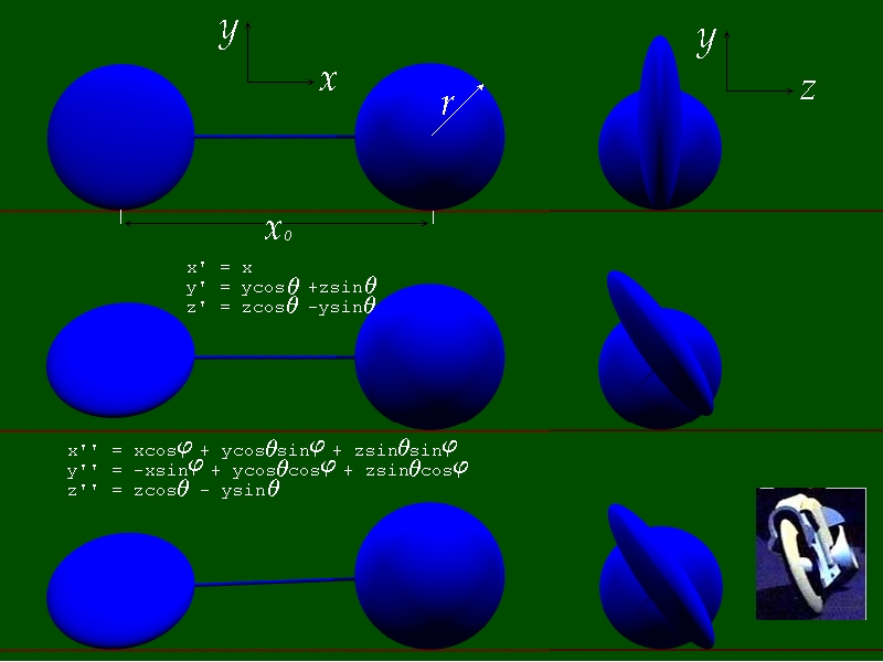
Oh its a language I know too well and I think this is something I should be able to do but so far my attemps have failed me. Here is a picture that I believe should help. The origin is at the center of the front wheel and its also the center of both rotations... the first is about the x-axis by the angle theta and the second is by and angle phi about the z-axis. Think of the problem this way if its simplier... I want to roll the dumbell composed of the two attached ellipsoids into the screen. After I've roled the perfect sphere by an angle theta what angle does the bar attaching the two centers make with the floor? Here is how I started... the floor is at y=-r. After both rotations the center of the rear wheel is at y = x0*cos(phi). To simplify the problem translate the rear wheel to the origin and that makes the floor now at: y_floor = -r - x0*cos(phi) NOTE: x0 is negative The surface of interest is now just: x''^2 + y''^2 + (z''/k)^2 = r^2 And I've defined x'', y'', and z'' in the below pic. How do I solve this for the minimum y? I don't think there will be a nice closed form solution but I'd love to be proven wrong. After I have the minimum y value on the surface of this elipsoid all I have to do is find the phi that makes y_min = y_floor. Make sence? If not I hope these pictures will help... Thanks to anyone that helps. I'll offer a custom light cycle scene to the first that can give me a solution. You can specify the resolution... number and color of bikes... their orientation.. if they have tails... etc. I've got a nice scene rendering now that's only 50% done after 9 hours. I'll post it when its finished. Later, Carl

-
Hey guys... Since joining the ranks of the unemployed I've taken the time to teach myself POV-Ray. After making my first wall paper and sharing it with Shawn he asked me "throw a light cycle up in the corner please :)" and I took that and ran with it. After not finding any accurate models of a light cycle on the web and not knowing how to get them into POV-Ray sort of helped... I created my own. Well... what do you guys think? Now for a mathematical question... I want to be able to put in an arbitrary angle of lean... lets call it theta. To keep things general my front tire is a sphere of radius r centered at x=0, y=r, z=0. Its surface looks like: ( x^2 + (y-r)^2 + z^2 ) = r^2 My back tire is a sphere compressed in just the z-direction by a factor that I'll call 'k'. Its centered at x=x0, y=r, z=0. And its surface looks like: (x-x0)^2 + (y-r)^2 + (z/k)^2 = r^2 Now what I plan to do is translate the bike so the front wheel is centered at the origin and rotate the bike by an angle theta about the x-axis. After this both wheels remain centered on the x-axis. Now if I just translate everything back up by r then the front wheel is still on the ground as its a sphere but the back wheel is up in the air. To fix that I want to rotate the bike about the z-axis by an angle phi till the lowest point on the rear tire is at y = -r before I translate the bike back up. So what I need is the best way to determine phi for a given theta. Can you help or point me in the right direction? The math is getting rather complicated and I've been out of school too long I think. Thanks for any help you can offer, Carl

-
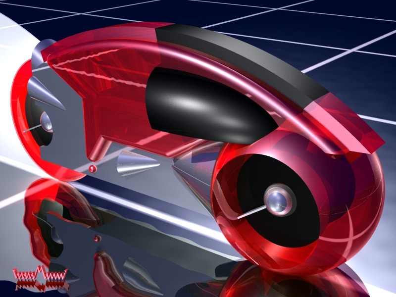
Well... I got this kit oh about a year or so ago I think: http://www.starshipmodeler.com/r&v/js_licy.htm Its a nice kit but took alot of work to make it look accurate. Still its a nice quality resin kit and I'd recomend it. I'm thinking about getting this kit: http://www.starshipmodeler.com/r&v/jw_tron.htm a try next if y'all like this one. And before I jump into the pictures allow me to apologize about the finger print over the rear wheel arch. I didn't notice it until after I added the clear coat over the top... Also I probably shouldn't have taken it outside to photograph. The glare on the grid in the foreground is a bit much. Still all considered I'm happy with how it turned out. Enjoy.... Carl
-
Yes... its a sererate part. I just went back and checked the pictures myself and its there. By the way... the kit itself is now on its way to Christopher, if its not already there. Take care of my baby as she's away from home. I trust you guys... just want to keep close tabs on her. Oh and very nice work Kaolian. Later guys, Carl My baby is back home safe and sound. Thank you Christopher. Later. Carl
-
I don't intend to let it come to that. I have several things that I'd sell long before things got that bad. My house might be one of them. And thanks again guys... for the last 7 years I've considered my co-workers almost as family. Now I feel like those of you here have been FAR nicer to me then they ever have. Carl
-
All, I've been here at MacrossWorld since the beginning so I hope this is ok. Anyways... long story short I just got laid off from my dream job. I hope to find another job soon but till then I'm not going to have any steam to help push on D'Stance or I.H.P. I ask the rest of you to help keep the ball rolling and I hope to be back in top form as soon as I can. Till then anyone know ANY PLACE looking for a Ph.D. in Condensed Mater Physics that has nearly 7 years of experience in the Semiconductor Manufacturing industry. I don't want to fill the board up with this stuff so if you think you can help I'm currently using drcarlhoff@yahoo.com. I'm in the Houston, TX area and I've got two boys in grade school and sports here and I hate moving but I may soon have no choice. At the moment I'll consider anything... A fellow fan that's bent over backwards to help when I could. And I've now found myself in need of some help. Even if all you have is moral support... I want to thank you so SO much in advance. Thank you, Carl
-
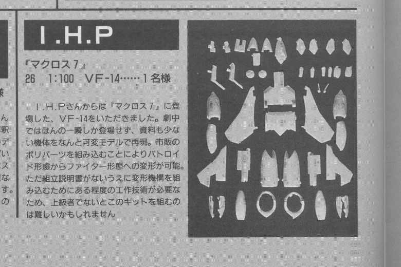
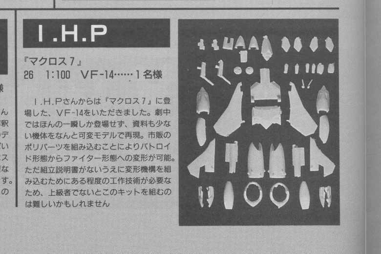
The IHP kit was a Wonder Festival only release. I don't have the exact date but I'd guess 1998 or maybe earlier. The other kit I know nothing more about. I'm still looking for this IHP kit myself. Oh and I know no information on the price of either kit. If you EVER find either anywhere PLEASE let me know... Thanks, Carl P.S. I just checked here: http://member.nifty.ne.jp/musyuku/ex.html#...l#Anchor2684352 If you can read Japanese this should tell you more. All it tells me is I think I'm correct about the date. Looks like this was sold at the Summer 1998 Wonder Festival.
-
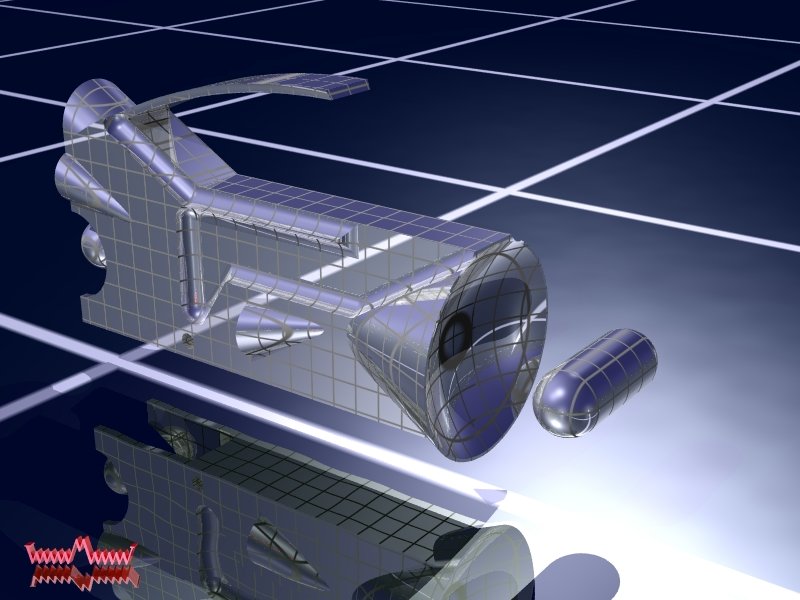
Here is another pic I wanted to share of the I.H.P VF-14