HWR MKII Posted January 18, 2005 Share Posted January 18, 2005 A very big thank you to Myersjessee and all those involved for making these kits available. Since Scand is doing his buildup on the 21 i will focus on the 19. The kits do not come with instructions but most parts only fit one way. There is light flash on most parts but that is to be expected from a recast. Im doing this as a build guide to someone who is new at resin modelling. I have built many resin models in the past and i have to say that the parts breakdown is unique. Another area i will be tackling is the red "sensors" on the nose. i will be forming replacement covers out of clear acetate and removeing the solid pieces. After i remove the solid pieces i will be installing sensor looking bits and installing the sensor covers. The cockpit is actually better than i thought. The only drawback is the seat. The origional mold maker used an injection molded seat for his master but i will be correcting the detail as best i can. Another piece i will be adding is the clear green bit that sits behind and to the left of the pilot. I have yet to see anyone add this part to their kit. I will also be adding a throttle and side stick assembly. More to come tomorrow with pics of a basic parts breakdown. But now its off to bed before another 12 hours at work. Quote Link to comment Share on other sites More sharing options...
scand Posted January 18, 2005 Share Posted January 18, 2005 Hey. I found these today while sifting throught the models section of the site. YF-19 Instructions Quote Link to comment Share on other sites More sharing options...
Myersjessee Posted January 19, 2005 Share Posted January 19, 2005 Sweet! I can't wait for more!!! Quote Link to comment Share on other sites More sharing options...
HWR MKII Posted January 19, 2005 Author Share Posted January 19, 2005 Well guys let us begin. These are not all the parts but just the major parts. i will cover the smaller detail parts as they come up for work. All of these parts make up the basic airframe. I WILL be making the Acft landing gear down. Quote Link to comment Share on other sites More sharing options...
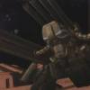
HWR MKII Posted January 19, 2005 Author Share Posted January 19, 2005 Here is the gunpod. As far as i can tell it is as line art accurate as it can possibly get. there was almost no flash on this part. The only clean up required is the careful removal of what appears to be tiny BBs of resin that became lodged inside the recessed details. to remove these i have a little Xacto blade with an offset tip that comes to a small point. it is perfect for reaching into the corners. Quote Link to comment Share on other sites More sharing options...
HWR MKII Posted January 19, 2005 Author Share Posted January 19, 2005 Next up is the nose. The pour stub at the front has been trimmed down before delivery(thankyou) but its remnants are still present. It is located mainly on the bottom of the nose. To remove this lightly and CAREFULLY shave off the bit until there is very little left on the piece. once you have it trimmed to almost the basic shape sand the rest off slowly and frequently checking your progress. You want to preserve the strake edge down the sides. Another thing you can see is the well formed shape of the sensor blisters on the nose. This will come in handy when i stretch form the acetate over it. more to come on that when we get to it. The cockpit tub has basic details for the sidewalls. the seat, up front display and equipment pack behind the seat are molded as seperate pieces. Quote Link to comment Share on other sites More sharing options...
HWR MKII Posted January 19, 2005 Author Share Posted January 19, 2005 Here is one of the "leg" engine pods. Of all the pieces these required the least amount of cleanup. The only things i will have to do is some light sanding of the seam lines and rescribe some panel lines. Quote Link to comment Share on other sites More sharing options...
HWR MKII Posted January 19, 2005 Author Share Posted January 19, 2005 These are all the basic airframe parts loosely fit together with no cleanup. The parts fit very well considering the flash on them. That is my recast 1/48 ultimate detail VF-1S strike next to it for size comparison. This kit will build up between the size of a F15E and F14D. Quote Link to comment Share on other sites More sharing options...
Kurt Posted January 19, 2005 Share Posted January 19, 2005 I look forward to reading about your progress. Did you have a lot of bubbles in the castings? The YF-19 I just finished was covered in voids from bubbles during casting. I hope you were luckier than I. Quote Link to comment Share on other sites More sharing options...
HWR MKII Posted January 19, 2005 Author Share Posted January 19, 2005 Kurt. My copy does have some bubbles but none are too big or in places that are important. The Smash forming went very well. what you need is thin clear acetate from a overhead projector or McFaralane toy. cut it into a 3x5 piece. Be sure to have extras since it may take a bit to get the hang of. Once you have your piece cut heat the center over a candle or heatgun( i have a heat gun). DO NOT get too close to the heat or you will burn through the plastic. Heat the plastic until it starts to sag in the middle then mash it down over the piece. The end result should look like a second skin of clear plastic. Quote Link to comment Share on other sites More sharing options...
HWR MKII Posted January 19, 2005 Author Share Posted January 19, 2005 Sorry the pics arent clear. It is difficult to take pictures of clear material and have it show. Quote Link to comment Share on other sites More sharing options...
HWR MKII Posted January 19, 2005 Author Share Posted January 19, 2005 One last note. When i build this i will minimize seams and joins but i will leave the mechanical joints in the kit that would be there for the acft to emphasize the fact it transforms. These will not be huge gaps but nor will i completely fill these seams. Another thing you must do on these kits is to lightly sand the surface of the parts and remove the grainy texture on the parts. The finish should suggest an acft made of metal not shark skin. Quote Link to comment Share on other sites More sharing options...
Myersjessee Posted January 20, 2005 Share Posted January 20, 2005 (edited) Im suprised to hear about all your bubbles Kurt...I didn't think any kits went out with that many...the main body was too big to pressurize...but the only bubbles I saw were usually inside the wheel well and in the cockpit...both would be covered by detail parts. The rest of the kit normally seemed tight. (or reasonably so) Anyways...you did a fantastic job...sorry about the extra work. HWRMKII....glad yours isn't bad. Can't wait for more. Edited January 20, 2005 by Myersjessee Quote Link to comment Share on other sites More sharing options...
scand Posted January 20, 2005 Share Posted January 20, 2005 Wow. is that how your making your clear lenses? sweet. As for bubbles, there are little to none in my kits. Quote Link to comment Share on other sites More sharing options...
HWR MKII Posted January 20, 2005 Author Share Posted January 20, 2005 (edited) I have carved out the solid detail and test fit a lense already and they fit great. This is a test fit sorry for the darkness but if its too bright you cant see the clear piece at all. I still have to fine tune the fit but this is almost good enough to glue in as is. I also have to make the pieces that go inside for the sensor itself since the lense will be clear red i want there to be a suggestion of something. Edited January 20, 2005 by HWR MKII Quote Link to comment Share on other sites More sharing options...
HWR MKII Posted January 20, 2005 Author Share Posted January 20, 2005 (edited) I cannot emphasize enough that you should take your time sanding and carving this resin. It is softer than most other resins but i prefer it that way. Resin that is too hard can wear down your sand paper before you sand the part down. For me this resin is perfect. The main bulk of the fuselage is together and the seams are filled but not sanded. i have not glued on the wings,fins,and nose. Also another thing i noticed was the master kit that this kit was made from is missing 2 things. 2 fins on the bottom of the fuselage between the arm pieces and the 2 internal cannons mounted near them nor is there any room to install them. Edited January 20, 2005 by HWR MKII Quote Link to comment Share on other sites More sharing options...
HWR MKII Posted January 20, 2005 Author Share Posted January 20, 2005 The greyish areas are where i had ti fill with a little putty. The only things i had to fill were large gaps where the wing root pieces meet up with the engine pods and some areas where there were seams from the molds not matching up right bit its the norm for any resin kit. I sanded down as much of the resin as i could without changing the shape then filled the remaining recesses with Squadron white putty. This putty is good for this kit since it is about as hard as the resin if not a little softer when dry. Quote Link to comment Share on other sites More sharing options...
HWR MKII Posted January 20, 2005 Author Share Posted January 20, 2005 Last one for now showing again the puttied areas. now im off to carve out the other sensor blister. Take it slow and easy on that and double check yourself as you go. Parts cleanup is a snap on these kits and they do fall together quite easily. To glue it together im using ZAP brand CA glue with a kicker. The ZAP is in the bottle with the green label and the kicker is to set off the glue fully once it is tacked in place so double check before you kick. if something is misaligned you can seperate the pieces with nailpolish remover or acetone. Quote Link to comment Share on other sites More sharing options...
Less than Super Ostrich Posted January 20, 2005 Share Posted January 20, 2005 Excellent! Glad for the review! Quote Link to comment Share on other sites More sharing options...
HWR MKII Posted January 20, 2005 Author Share Posted January 20, 2005 Thanks LTSO well i have the whole basic airframe assembled and i have to say the kit is good. The ONLY snag was that one of the wings is thicker than the other so it does not sit flush on the bottom. I glued them so the tops are both flush and even with the root piece and left the seam to show the moveable nature of the wing on the acft. One wing fit perfectly the other im going to have to feather in with putty on the bottom but it shouldnt be very noticeable when the whole project is finished. I have also been test fitting the intake pieces as well. These look like they will fit ok with a little tweaking but the parts are so thin i have already broken one (its fixed) because they have to be bowed in a little to fit into the grooves placed for them. pics to follow tomorrow Quote Link to comment Share on other sites More sharing options...
Myersjessee Posted January 21, 2005 Share Posted January 21, 2005 Looking really good! Nice work! Quote Link to comment Share on other sites More sharing options...
HWR MKII Posted January 22, 2005 Author Share Posted January 22, 2005 ok here are some more pics for you guys. IM sorry for the blurr but i have no good lights in the house. first the upper fuselage with a light coat of primer on it. Quote Link to comment Share on other sites More sharing options...
HWR MKII Posted January 22, 2005 Author Share Posted January 22, 2005 Now the nose. You can see the indentations for the sensors. The clear parts are both trimmed and painted clear red ready to go. im going to keep the installation of those for last you guys will just have to wait to see how they work out. Quote Link to comment Share on other sites More sharing options...
HWR MKII Posted January 22, 2005 Author Share Posted January 22, 2005 Now the problem wing. the dark pinkish stuff in the wing root is Bondo. It had the quickest cure time and best sanding qualities for feathering the pieces together. Quote Link to comment Share on other sites More sharing options...
HWR MKII Posted January 22, 2005 Author Share Posted January 22, 2005 Now for the seat. The seat looks like it was taken from an old Monogram Tomcat. Im going to create a new headrest for it and make some of the overall appearance more accurate to the animation. This is the seat before cleanup. Quote Link to comment Share on other sites More sharing options...
HWR MKII Posted January 22, 2005 Author Share Posted January 22, 2005 Side view of the seat again. Quote Link to comment Share on other sites More sharing options...
HWR MKII Posted January 22, 2005 Author Share Posted January 22, 2005 Heres the parts breakdown for the exhaust nozzles. Notice the flash around the edges and pour stub on the larger piece. Quote Link to comment Share on other sites More sharing options...
HWR MKII Posted January 22, 2005 Author Share Posted January 22, 2005 The flash on the parts was light enough to shave off with an exacto knife and touch up using a fine sandpaper. The pour stub on this piece was carved off and sanded as well. The resin feels exactly the same as carving a piece of balsa wood. Quote Link to comment Share on other sites More sharing options...
HWR MKII Posted January 22, 2005 Author Share Posted January 22, 2005 Heres the nozzles cleaned and assembled Quote Link to comment Share on other sites More sharing options...
HWR MKII Posted January 22, 2005 Author Share Posted January 22, 2005 Another view. Quote Link to comment Share on other sites More sharing options...
HWR MKII Posted January 22, 2005 Author Share Posted January 22, 2005 Here is a nozzle after paint. I sprayed them flat black then applied SNJ rub and buff silver leaf paste. I rub the paste on with my finger tip and then buff it with an old Tshirt to bring it to a sheen. if you get some paste on the area you need to keep black you can just paint over it with acrylic to clean it up. Quote Link to comment Share on other sites More sharing options...
HWR MKII Posted January 22, 2005 Author Share Posted January 22, 2005 Once you allpy the paste you can get a really high sheen to it. its a new technique i wanted to try and seems to have worked well. i wanted a nicely maintained clean look for this model. There will be some slight weathering to give the subject life but it wont be too heavy. Quote Link to comment Share on other sites More sharing options...
HWR MKII Posted January 22, 2005 Author Share Posted January 22, 2005 Final shot for the night. This one shows off the different effects in the highlights from the buffing. The edges pick up the light really well. Quote Link to comment Share on other sites More sharing options...
HWR MKII Posted January 22, 2005 Author Share Posted January 22, 2005 Here is the more accurate seat. I sliced the headrest of the kit seas and trimmed the front where the pilots knees go down to normal size. Then i took a piece of sprue from another model and glued it across the top of the seat. make sure you put the sprue slightly foreward not dead center. After the sprue is glued and dry cut the ends flush with the seat and fill the step behind the sprue piece with white putty. Once the putty is dry sand it down at an angle from the back of the seat to the headrest. Carve the sprue piece in 3 equal sections to look like the padding on it. Then i filled the ribbing in on the kit seat and sanded flat. After you have done that cut strips of sheet styrene plastic out to make the padding on the seat itself. the end result should look like what you see here. I have the hasegawa seat next to it. The Hase seat and Macross plus were my only available references to do this. Quote Link to comment Share on other sites More sharing options...
HWR MKII Posted January 22, 2005 Author Share Posted January 22, 2005 What were those red things in the pic above you ask. HE HE yup its the lenses fully trimmed ,fitted ,and colored. This is the last you will see of them until i get the initial painting done. ENJOY! Quote Link to comment Share on other sites More sharing options...
Recommended Posts
Join the conversation
You can post now and register later. If you have an account, sign in now to post with your account.