danbickell
-
Posts
242 -
Joined
-
Last visited
Content Type
Profiles
Forums
Events
Gallery
Everything posted by danbickell
-
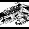
While I continue to impatiently wait for my Shapeways order, here's a little bit of what I messed around with earlier today when I had company over: A little more serious lighting and a backdrop (WIP Prometheus model) does wonders, and I haven't shown it with the gear down recently. Ok, back to the waiting...
-
Nah. He meant "dance, monkey!", and I wouldn't hold it against him either. I will be happy to get the DYRL version of the VF-1 done. I should hopefully be able to work a J head and FAST packs in there too. I would *like* to get around to GPB armor, and a TV versiion VF-1 as well. I'd also want to do the 2 seaters as well. We'll see, I'm not getting any younger... I would love to do a VF-4. Unfortunately, there just isn't nearly as much reference material available, so it could never get the same treatment. Having the Yamato toy would certainly help with that though. I've got a lot of VF-1 stuff to work out before I would ever get there. Shapeways update: 1st delivery attempt failed. I hate living in a gated complex... I left a big sign out for him with my phone #, and have been impatiently waiting all day. Even had my buddy and his boy over, (more patiently) waiting with me. Despite going outside every time I imagined I heard what could possibly be the UPS truck, I managed to miss them. I nagged customer support, and arranged to go make a pick up at will call later tonight.
-
Thanks! If Kawamori-san manages to see it, I would simply hope that he recognizes it for the labor of love that it is. No doubt, my path through life, and the successful career I've had as a digital artist, would not have been the same if not for the influence of his work. So, in more ways than one, this would certainly not be possible without him. Or, maybe he would just think that I'm a giant nerd, who has put way too much thought, effort, and time in to such an endeavour. And, he would be right, but it wouldn't stop me from doing it all over again through the years to come, hopefully getting better each time! Latest news: I got my shipping notice from Shapeways yesterday. The design did not get rejected! I'm still somewhat surprised that I managed to get it right on my first try, but perhaps it was beginner's luck. The 1/24 scale VF-1S head model, in frosted ultra detail, is on schedule to arrive by 3pm today. I doubt I will get much sleep, but I will be sure to post an update with pictures. We'll see what went right, and what went wrong, in the next 12 hours...
-
I completely agree that a swing bar like that makes a lot more sense, from a structural standpoint. From the bigger picture, the problem a setup like that on the VF-1 causes is proportional. Just like the toys, it requires space between the back/underside of the nose and the back/wings, and that space should not be there. This is the biggest factor in why the Yamato toys are proportionally too thick front-back in battroid. It seems to be a decent tradeoff in the toys, because it allows some extra room for the hips to pitch back and forth, giving extra posability. But, therein lies another problem, at least in the way I see things. I don't think the intakes/hips should pitch back in forth much at all. They should mainly yaw (spread apart or close the legs), but the pitch should primarily be the job of the joint between the thigh and the hips. Everything about the transformation mechanisms I've worked out in my model is all about getting a slim and tight battroid torso, as close as I can get it to the line art without anime magic/cheating. Besides not wanting to do anything non-canon, a setup like that would undo everything that has been done to keep the chest and back as close together as possible in battroid. Having the gap between those parts as narrow as possible is also key to any hopes of having functional battroid side covers.
-
I wondered, while that was rendering, if anybody would notice that. The mechanism is worked out, but not detailed yet, so you aren't missing much. I'm trying to keep it as close to the transformation drawings that were originally done, but the key difference is that the hinge panel is 2 pieces so that it can extend in length to line up the hip joints. Instead of having the actuator pistons on a sliding mechanism (which really doesn't make much sense), the sliding mechanism is for the extension of the hinge panel, and the actuators are anchored at a fixed point up above the LERX body, occupying some space under the chest (which allows for a space for the collapsed pistons above the LERX when closed up).
-
Hehehe. Yeah, I do spend a LOT of time scouring the lineart. Up until now, that's meant always surrounding myself with books, many stacked open to specific pages, and spending time scanning the stuff that I keep going back to. The resources you sent my way are an ENORMOUS help! I've been in the process of getting a bunch of it on my iPad today. I think it might just be the ultimate use for a 64 gig iPad 3. My workspace just got a whole lot less cluttered. Thanks again! All the research involved with this is half the fun. I love pouring over the material, taking note of all the little differences here and there. I love it most when I'm paying specific attention to a certain detail I'm working on, and seeing details I never noticed before, despite the decades spent with the same old old reference. I just noticed for the first time the other day that one of the DYRL drawings showing the revised main landing gear (kinda F-18 style) has the light removed from the forward nose gear door panel and relocated on the nose gear strut. Other DYRL drawings still show the original round light on the door panel. That hand hold is something that always stuck out to me in that particular drawing, though. It makes me ponder why that decision was made, and sparks my imagination. I think it is easy for us to get stuck in a certain mindset about the design, based on our knowledge of real-world modern aircraft design. Of course, this isn't "real-world", and even the "modern" part only loosely applies, not only because it was actually designed in the early 80s, but even in-universe it is a parallel reality where we encountered alien technology in 1999 and have only had a decade to reverse-engineer it. Even the "aircraft" part only partially applies, as this is mecha that happens to have a transformation mode that mimics aircraft, and even then that only really applies for atmospheric flight. If we were to imagine at some in the Macross universe, after the VF-1 was no longer in regular service, I wonder what data might exist showing the percentage of time the VF-1 service hours were in space vs atmospheric use. In the long run, I would guess that space hours vastly outnumber atmospheric use. How much of our real-world aircraft design sensibilities truly apply to something like the VF-1? How much gets compromised by the needs of space flight, or the mecha concerns of transformation? How much does aerodynamics continue to matter when you have a relative abundance of thrust? Back to those hand holds... I can imagine the scenario where the earliest variants might have had a spring-loaded panel to cover those, like one would expect on a modern real-world aircraft. Maybe that is something that later got deleted, because it just didn't matter in space, and it wasn't having any significant aerodynamic effect in atmosphere because they are downstream of the turbulance from the nose verniers? Maybe they decided to delete them because gloves had a tendency to snag on the edge of the open panel when pulling out in a hurry, which became a serious issue for space flight suits. The smallest details can be totally interesting like that. I wonder if Kawamori thought about stuff like this, or if he just decided to do something different for the hell of it. I don't suppose it ultimately matters. What matters is that 30 years later, we the fans are talking about this stuff!
-
I considered that about the hand-holds. Hasegawa clearly made it a hinged panel on their 1/48 model, but that isn't how Kawamori drew it on my favorite of the DYRL detail drawings: I kinda like that it breaks up the surface. Of course, I know it isn't good aerodynamic design, but the VF-1 is full of such things already. The vernier thrusters on the nose are a much bigger offender in that respect. You guys probably won't notice anything different about the nose. The shapes and details are the same, the geometry just has different topology. Sub-d just allows me to crank up the poly count, so the round curves can be as round as I want/need them to be. Most of that is already done. I was just showing a buddy who stopped by to visit, and he didn't notice anything different at all. Where it would be noticeable is how not faceted the surface would be should I do a 3D print. The only thing that might change would be the areas under the canopy frame. I put some shapes in there, like a seal, but I've never been happy with the lack of detail, so I might address that while I'm revisiting the area.
-
Yeah, at the very least, this 1/24 S head will be a fun experiment, and not overly expensive. My expectations are low, but maybe we'll be surprised. Maybe it will turn out great, and steer me towards attempting more. Maybe it will serve to get the idea out of my system and save it for the future when the technology advances enough to meet my high standards while being fairly affordable. Browsing through the stuff people have available on Shapeways, there is very little that comes anywhere close to this level of detail and complexity. I certainly don't think that has anything to do with a lack of 3D modelling talent out there. It all seems to just come down to the practicality of the medium. Kurisama's work is easily some of the best I see there, and designed specifically for this purpose. Still, practicality sets the limits. In order to make it available at a reasonably affordable level, it has to comply with the limitations of the cheaper materials. I'd be curious to see how some of his parts would come out in the FUD material, but then we're looking at more than doubling the prices, which would make for a rather expensive upgrade kit. I would love to see this VF-1 model in 1/32 scale. It would be a nice manageable size, and would cut down considerably on the theoretical costs. However, I just don't think it is in the cards with the current 3D printing technology. It would require a completely different model, designed for the scale, and the end result would have to be less detailed than we already see in a good injection-molded kit like the Hasegawa 1/48. Yet, the price would still be several times over what the smaller and more detailed injection-molded kit costs, so why bother? I've been busy converting the older parts of my model to sub-d (mostly just a lot of re-topologizing), to match what I did with the S head. If I continue moving forward with the 3D printing, this will facilitate that. If not, it is allowing me to go back and fix a few things that have bugged me, and allows me to easily crank up the resolution as much as I like. I started out too low with the poly counts, having a hard time breaking my habits from decades of game modelling, and found myself making things increasingly higher resolution as I moved on. The nose is getting an upgrade to make it comparable with the newer parts New page in the thread deserves some new pics. Here's the last few progress renders I made, parting shots for the old nose:
-
I do expect to see much of the smallest details lost. Much of the panel lines and such are right around the minimum detail size for the FUD material in this scale, so I'm curious to see what shows up and what doesn't. I have certainly paid attention to your work on Shapeways, and I can already see how how much differently I would approach a project intended specifically for 3D printing in a certain scale and material target, compared to how I've approached this model. In my dreams, that is exactly what I would want to try. The detail would have a much better chance, and there wouldn't need to be compromises for wall thickness. If only volume merely doubled when you double the scale! A head might not be completely out of the question, but the whole VF-1 would cost several thousand $.
-
It can be fun to speculate about in-universe rationalizations for why the various variable fighters are the way they are, but the reality is simply that the VF-1 was the first attempt by some young guys to create a design like that, and they couldn't have had any idea that it would have to stand up to scrutiny from a bunch of nerds like us for all these decades. They clearly learned their lessons though, and it shows all from the DYRL re-design all the way to the numerous variable fighter designs since (even the one that is supposed to be the VF-1 predecessor). It is funny how so much of it came in baby steps, that don't make a great deal of sense in the order they are supposed to be developed. The cockpit displays/battroid screens are a great example. They made the step in DYRL to remove the traditional HUD and replace it with using the whole canopy as a HUD, yet they didn't make the next logical step and use this for the battroid screens (projected lines, reticules, and data on plain old glass was probably as far as their 1984 mind-set allowed). Instead, they designed a completely new battroid cockpit that still has conventional screens, and still didn't make much sense in the space provided. They made the next step with the YF-19's cockpit surrounding displays providing a downward view in fighter that ends up being the forward view in battroid without needing to transform any of it (the seat rotates forward 90 degrees, and all the controls are attached to the seat). Eventually, they come full-circle with the VF-0 battroid cockpit, which borrows from everything learned from the previous designs (previous in the real world, that is) and makes the same type of configuration as the VF-1 actually make sense and work. Makes me wonder what we would see if the VF-1 got another re-design for a modern reboot of the original series. Yes, I ordered it last week, and just got the email this morning confirming that it went into production. They say it should ship out by the 25th. Being a first-timer with Shapeways, I was wondering if I can now assume if that means that the design has not been rejected, or if it simply means that they are about to try to print it and will reject it if there are problems with the print. I'm real curious to see how it turns out too! I attempted to lay it out in a way that it will only fit in the space of the printer in one orientation, which would be optimal for where the "frosted" areas would end up (the parts that don't come out as smooth, due to contact with the wax support material). However, this could still be completely thwarted by them printing additional orders at the same time (which they reportedly do) if my order isn't on the top of the stack. If that's the case, I guess my only hope is that the printer operator favors the model that is likely more interesting, intricately detailed, and expensive, and puts it on top! I wonder if they frown on people getting around this issue by building a thin frame around the whole thing that takes up the entire printable volume, forcing the desired orientation and making it impossible to print another order on top of it all...
-
Oh, if I had a buck for every time a concept artist gave me a piece of concept art that didn't actually make any sense in 3D... I've tried to teach them how to make plan views of a design and make everything line up between them, but it just slows them down too much and they don't seem to learn. I think spatial perception is just inherently linked with intelligence! The battroid cockpit is certainly more feasible than the battroid seat egress, for sure. The seat doesn't even move that much in the DYRL deisgn. It does not rotate 90 degrees like the TV version does. The head rest tilts back, and the seat rotates back maybe 45 degrees. The pilot has to look up to look forward (and it looks like it would be quite uncomfortable in real life). That is how it would have to be, though. The cockpit tub angles up immediately behind the seat (the deeper portion of the landing gear bay is directly underneath, room for the wheels), so there's nowhere for the seat to rotate back too. The bottom of the seat has to rotate up as much as the top is rotating back. The only way it could rotate 90 degrees and move back (back in battroid) for more space would be if it moved forward (in fighter, down in battroid) first, so that it would lay on the floor. There are big problems with that, though. The the stick and throttle are supposed to pivot up into place for battroid, but the seat would no longer be in the right place relative to them or the pedals. Also, the seat needs to stay where it is because that is the widest and tallest part of the canopy, and there would have to be enough room for the battroid screens to maneuver around the seat and pilot. There already isn't really enough room for this, but if you move the seat forward or backward, this room shrinks. So, you can see why the DYRL design was changed the way it was. It could be made to work, but it certainly wouldn't be very ergonomic. Unfortunately, none of the battroid cockpit screens detailed in the DYRL line art match with anything in the fighter cockpit. To make it work, the box behind the seat in fighter would have to transform into the screens, with arms inside the move them around, and they would need to either be very small or bendable to get between the canopy and the pilot and seat. At some point, I would like to make the DYRL battroid cockpit as a separate model, but I will just model it as designed. Forget about making it actually transform.
-
Yeah, a big part of the Master Files solution was to have the whole nose landing gear bay move outside of the nose (behind it in battroid). Part of what cracks me up about that is they were utilizing the space that the toys have behind the nose in battroid (for the swing bar mechanisms), and that space shouldn't actually be there in the first place! I could go on at length about everything in that scheme that works ok in a 2D diagram, but makes zero sense in 3D, and alters far more about the established design than it fixes by making that battroid seat egress possible. Personally, I think it lessens the design to start moving parts around that shouldn't move. The nose is the central piece of the whole, to which everything else attaches. It really should be a solid piece, not some reconfigurable shell that anime magic happens inside of. It should be a solid framework. The floor of the cockpit and the roof of the landing gear bay are one and the same. Their shapes and sizes are defined by each other. It is part of the frame. It is a bulkhead, with an ejection seat and flight controls attached to one side, and landing gear attached to the other. There isn't even enough room in there to make them into separate volumes that could move around each other somehow (and certainly not without substantially decreasing the sizes of everything contained within). Even if we ignored the issue with the landing gear space, there are still plenty of other space problems with the idea, and it would require throwing out a whole lot of the established design to accomodate this one impossible feature. The cockpit tub would need to be a completely different shape (and this shape is well-defined in the DYRL cockpit side view diagram). The box behind the seat would have to dissappear (or somehow become the battroid screens that magically extend around the seat without decapitating the pilot!). The cavity at the back of the nose (that the head fits inside) would need to be an entirely different shape (than what was shown in the lineart) to allow for some big doorway to open up for the seat to come out of. The outer opening is barely big enough for the seat (forgetting that the DYRL design also has the armrests coming out with the seat somehow, and that a pilot needs to be in the seat and not get his legs cut off), but the inside is much too small. I was watching the TV series over the weekend, and taking note again of how much different the battroid cockpit is compared to the DYRL designs. The TV design is much simpler, but the big caveat there is also how this impossibly big space suddenly exists within the nose somehow. A VF-1 nose is actually very small compared to most fighters. They accurately show this often in fighter, but somehow in battroid there is suddenly this huge room inside that doesn't resemble anything that could possibly be inside the nose. It actually looks a bit like I would expect if it were a live-action show, and they had to build a battroid cockpit set, purposely made over-sized to allow room for lighting and variouis camera angles. As far as the intake leading edges, I'm fine with exploring that. Even the "right angles" that exist in the V1 design are rounded off on on the inner and outer sides already, but I will experiment with rounding them all the way around (so that there are no flat areas left). The trick will be doing this more at the bottom, while the top doesn't change much. As it is in the V1, those flat "right angle" areas at the top edge are really only 30 or 40 degrees off angling straight into the intake interior. I'll see what I can do with it.
-
Not to worry! I keep backups on an external drive, and on a flash drive as well. When it is all done, I'll make extra backups and put them in a safe. I'll leave instructions in my will to donate the data to Macross World upon my death.
-
I think I know what you mean by that, but study the line art a little closer. There are at least 3 front views in the line art that show the contours at the bottom that the Yamato helmets have. None of the side views have any representation of them drawn, but the contours have to be present (and at least very similar to Yamato's representation) in order to match those front views. I think Yamato did a great job in interpreting those shapes with soft edges, matching only the hard edges to what was drawn for all the other angles. That's actually something that all the other representations seem to have missed. This motorcycle helmet puts too much of a sharp edge in there, and doesn't curve it to match the contour that the line art consistently shows from the front. I think the Yamato is the more accurate representation, actually. I have the Yamato Fokker helmet, and it certainly is huge! However, if you look at the exaggerated proportions of the drawn characters, it actually makes sense. I think if you took one of those Toynami 1/6 dolls, and blew up the helmet to 1/1 scale, it would be about the same size as the Yamato (maybe even bigger). The shape, however, wouldn't match the line art nearly as well.
-
Lasers, of course. That's why I made the rifling straight instead of spiral. It must be some sort of focus mechanism, for accuracy adjustment. Or, whatever... I just wanted some cool detail. Let me get some test pieces first, so I can see how they turn out and make any adjustments that might be needed, but I would be happy to make them available. Would people (other than me) actually want to pay over $100 for a 1/24 DYRL VF-1S head? The whole valk would have to end up over $1000!
-
Ok, so I was off by $5.09... I noticed with my first upload of just the head guns that I could see facets. Duh. 3d printers don't care about vertex normals, so I just need to throw more geometry about it. I spent several hours making a sub-d version of the model, and cranked up the polycount. I looked up the dimensions for Frosted Ultra Detail, and fit everything nicely within the box. I know Shapeways might orient it whichever way is convenient for them, but I went with a layout that would put as much of the wax support material in places I don't care as much about. I had to play around with the sub-d iteration levels, but eventually I came up with a file less than the 64Mb limit, at around half a million polys. Here's a render of what I sent: I left out the clear parts. They are just way too thin, and they don't have any decent enough transparent materials yet anyway. I ended up putting the eye clam shell doors on a sprue (attached to the eye detail part), and had to beef them up considerably to get the walls thick enough. Those parts will have to be manually thinned back out to fit, but better than not having them. I went around the model with a 0.3mm cube (FUD minimum wall thickness), checking wall thickness, and everything looks good to me. There is plenty of detail that I think might be too small to show up, though. It all STL checks just fine, and passed the upload check, but I wouldn't hold my breath that it won't get rejected for something or other.
-
I was hoping you might show up! I've been checking out your work, and paying close attention. Any input you have would be greatly appreciated, when you have the time to spare. This will be my first attempt at printing, and I feel like I have no idea what I'm doing!
-
Thanks for the opinions. I'm still leaning toward V1, but I might experiment with a V3 somewhere in the middle. I made some good progress working out the LERX leg transformation mechanisms, but I've been side-tracked for the last few days experimenting with preparing the S head for a first attempt at 3D printing. Of the few areas of the model that weren't already water-tight, the eye detail area was the biggest offender. It took a good 16 hours to boolean every little detail together and clean up the geometry (could just boolean it together and not bother with the clean up, but I'm pretty OCD about clean geo). The eye detail piece is a 65k poly model, by itself. I experimented with uploading a 1/24 scale version of just the S head guns to Shapeways. The first version (solid) came out to $32 each in the frosted ultra detail material. So, I made a hollow version, and got the price down to $15 each. Learning from that, I made hollowed out versions of the rest of the S head parts, and made a 2-piece neck (neck rings can't be slipped over a 1 piece neck). Almost everything STL checked with zero errors on the first try, but nobody's perfect! Here's what it currently looks like, all apart and laid out: Next I need to figure out how best to lay it all out, and whether to connect parts with sprues or not. There's a few potential problem areas I forsee: Scale - I want to try 1/24, but it is pushing it. The only material with minimum wall thickness and detail size that looks like it might work at this scale is the frosted ulltra detail. Even then, the smallest of details would be smaller than the 0.1mm limitation. The thinnest walls look like they might be the gun barrels (they are hollow, and go all the way back), but at the thinnest point it should still be at least 0.5mm, and the FUD minimum wall thickness is 0.3mm. The clear pieces will probably have to be left out for now. The visor is 8mm thick at 1/1 scale, and there is no room for it to get thicker without re-modelling and moving details around (there are lips for the visor to sandwich into). 1/24 scale put that at 0.33mm thick. That's barely within the minimum for FUD (which doesn't look clear enough anyway), and the transparent detail material needs to be 1mm thick. The smaller lenses are much thinner, so no way to do those in such a small scale. I'm guessing the whole thing would be well over $100 in FUD in 1/24 scale. The guns alone would be $30. 1/12 scale would be nice, and would probably get around any detail size and potential wall thickness issues, but I assume that would be getting pretty expensive for a test. Any tips or tricks for how to lay out parts and/or connect them before I do a trial upload would be appreciated!
-
Did some exploration with modifying that intake leading edge. Here's what I came up with: I'm still on the fence about it. I think it looks pretty good in fighter, but not so strong for battroid. And, while it does look more realistic for fighter, it feels like more of a departure from the lineart. It also creates a bit of thin edge at the top, which could cause some 3d printing problems. Opinions?
-
My theory about the intake fan is that isn't part of or connected to the engine in any way. It is just an electric fan with the purpose of keeping the air flow when the legs are bent and and there is little or no forward movement scooping in air (like in gerwalk mode). I guess it would have more in common with the lift fan on the F-35B, rather than any part of the compressor. I figure that the intake covers must be able to act like the F-14 variable ramp. There really isn't any other reason for them to be as segmented as they are if the only shape they take is fully open or fully closed. That could easily be accomplished with a 2-piece intake cover, rather than 6 pieces. I hear you about the leading edges of the intakes, and I might revisit that. I played around with a few variations on it while I was building them. I noticed that the model kits (like the Hasegawa 1/48) tend to make the intakes more like a realistic jet intake, and less like the original lineart (especially the battroid lineart). They tend to square off the cross-section of the opening, and make the leading edges thin and aerodynamic. Aesthetically, I wanted to make them look beefier and more structurally capable of being the battroid hips, which is why I went the direction I did. I kept the walls of the intakes as thick and sturdy looking as possible, and kept the inside of the intake very rounded and smooth. What I could do better is to keep all that thickness but extend the inner edge of the leading edge forward, so that we get a sharper edge on the inside, with a taper curving back to the outside. That would be look more aerodynamically sound, while still suggesting it is as beefy a structural piece as it needs to be.
-
There's no reason the fan blades couldn't be made to turn their angles. I did a fair amount of research, looking at modern turbojet fans, and I don't recall seeing any with variable pitch blades. They do typically have quite a severe angle, though, and I went with that to limit visibility behind them. Having a single piece fan would also be preferable for any 3D printing (otherwise you're going to need 33 pieces for each fan!). Those fans are certainly an interesting part of the design, though. Of course, in a real-world turbo jet, those are shaft driven parts of the engines. In the VF-1, it would have to be more like a self-contained electric motor powered by the reactors, just providing airflow in gerwalk or at low speeds. Agreed. They do look a lot like the way the battroids were drawn in the lineart. The arm and leg proportions aren't too far from what is workable for a fighter proportioned like the Hasegawa 1/48. The torso has proportional issues that wouldn't work out too well, though. The nose is much too short, the chest is very rounded out, and the wings and vert stabs have been shrunken down considerably. They did improve dramatically in the 2nd book, at least some of the models they used. The ones they used for all the battroid and GBP illustrations do look pretty good. You can see the evolution of those guys figuring out what works and what doesn't. I wish they had more consistency (one model to rule them all!), but they needed enough content to put these books together that they had to draw material from several different artists. One artist can only do so much...
-
Well, where they went wrong with the Master File books was having skinny legs. It looks quite close to the Hasegawa 1/72 model, but with the legs straightened out (but the same proportion). This doesn't leave much space for arms, unless they were to protrude quite a bit in fighter. So, the end result is the twig arms. All the original lineart takes liberties with the proportions all over the place. They shrink the legs and arms down to make a sleeker looking fighter, and then they get big and beefy in battroid mode. Likewise, they beef up the chest and shrink the nose in all the battroid lineart, where they keep the nose long and the chest flatter in the fighter lineart. More anime magic. That goes right back to why I've been so enamored with the Hasegawa 1/48 proportions. They bulked up the legs to similar proportions to the Yamato 1/60 V2, and lowered them to keep them straight. The whole profile is a bit taller than the original fighter designs with a taller chest and lower legs, but I think it looks really good (gives it a bit of an Su-27 flavor), and it really helps out the proportions for battroid. There is plenty of space left for nice big arms, without having them protrude too low (like the Yamato 1/48 arms). I found it to be such a beautiful, realistic, and a bit more modern interpretation of the iconic design, that it drove my motivation to start this model in the first place. See page 2 of this thread for the old image I posted demonstrating the proportional differences between the various models.
-
If anything, I think making an SD version could help out the transformation more than hurt it. Proportionally, you can give yourself bigger volumes to work with inside an SD shape. You could probably probably even make things like the battroid seat egress work, with a big fat nose section. The beauty of it is that you can proportion anything to where you would need it to be. That sounds WAY easier than making everything work while constrained to the original shapes and volumes. The trick would be coming up with proprotions that would look good and work at the same time. I could see the head being a problem, as big as you might want to make it SD. I have not actually made the working ladder yet, but I did plan for it. The panel lines for it are there, and it would just need the telescoping mechanism added. I should add it when I go back to the nose to add the hip pin mechanism. Thanks for reminding me! I decided on the telescoping ladder design from this example of the original lineart (which also shows those vents on the outer upper corners of the intakes BTW): The grip hole is also in my favorite of the DYRL detail drawings. This setup works nicely for me, and also matches the Hasegawa 1/48 plans. Despite the "NO STEP" on the LERX, I can't imagine a pilot wouldn't use the LERX as well, as it is lined up perfectly with the ladder and grip point.
-
For the most part, the meshes are water-tight. I'd say about 90%. There are small details in some places that would need to be booleaned together, and I would have to add some back faces to close some parts off, but I've always had 3d printing in the back of my mind for this. I might try a piece or 2 as a test in the near future.
-
Ok, here are a couple of teaser images, with the rest of the WIP undetailed parts I have worked out so far: One of the parts I'm focusing on here is the connection between the nose and the chest. In a number of the DYRL drawings, this is shown as not flush between the 2, like on the TV version. The side nose profile cutaway sketch shows this, as do a number of the detail drawings done for the DYRL cockpit. I've always liked this, but never seen it done quite like it was drawn. The Club-M 1/48 had the details from one of the detail sketches as panel lines, but made the connection flush. Here's a shot of it all in battroid mode: I'm pretty happy with where the proportions are now, and that the top of the shoulders is without gaps. I should be able to detail that to look pretty close to that DYRL battroid sketch we keep referencing. The only open space up there is that area behind the head, which will get filled up a bit by all the cool details on the underside of that hinged back panel. Of course, this is all what I call "block-out" geometry. It will get considerably refined as it gets closer to final and detailed. I can't wait...