danbickell
-
Posts
242 -
Joined
-
Last visited
Content Type
Profiles
Forums
Events
Gallery
Everything posted by danbickell
-
Progress renders of my CG DYRL VF-1 model
-
-
From the album: DYRL VF-1 WIP
© Dan Bickell 2012
-
From the album: DYRL VF-1 WIP
© Dan Bickell 2012
-
From the album: DYRL VF-1 WIP
© Dan Bickell 2012
-
From the album: DYRL VF-1 WIP
© Dan Bickell 2012
-
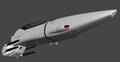
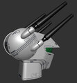
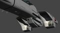
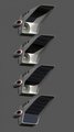
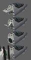
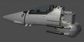
As promised (for once!), I think I'm finally done with the intakes. Have a look: The design I decided on for the hip joint is loosely based on an old 1/72 battroid vinyl kit (don't remember who made it). This type of design solves a few problems that often bothers me about the VF-1 design. It provides room for a good sized ball joint while not intruding into the space for the inside of the intake, and it takes up a good chunk of the space between the intake and the nose blisters in battroid. I really don't like long skinny hip pins, and this allows for a beefy pin that is nice and short, and not super visible in battroid. On top of the intake is the connection point for the transformation mechanism under the LERX. Also included are the 3 vents on the outer sides. These are prominent on the Hasegawa 1/48 model, and vaguely shown in at least one of the original fighter lineart drawings, and more prominently in the more detailed battroid lineart. Only a small portion of them protrudes below the fairings on the underside of the LERX and chest, but they are more visible in battroid. I went through a few iterations of the forward-facing vernier thrusters (the brakes!). That's the same thruster bell from the nose verniers, for consistency. I decided to make the vents on the rear of these more decidedly rear facings, as would make sense aerodynamically. Most of the time these are interpreted as if they would just vent straight out to the sides. Also, instead of making all 3 the same height (like most models, even the Hasegawa 1/48), I decides to have them follow the curve of the part. One of the trickier parts of this, even though it might not look like it, is the intake covers. These were often drawn, and have often been interpreted, in ways that just don't make sense. They would have to pivot on multiple axes and change shape much of the time. The Hasegawa 1/48 did better than most by having the hinges all parallel, and the front one not following the angle of the outer intake. They also cheated the inside of the intake as very squared off, which I don't like the look of. The trick was getting nice curved corners on the intake, with a nice flowing aerodynamic intake interior, and intake covers that fit well in any position between fully open and closed. After lots of tweaking, I finally got it to a point where I was happy with it, and you can get quite a number of configurations suitable for different conditions. Of course, I had to have the fan nice and visible! It actually sits a little behind the intake (inside that black temp cover I added for these renders), and will be contained inside the joint between the intake and the thighs. It is a 32 blade design, complete with recessed bolts for each blade in the cone. I have fun making sound effects while I spin it. I'm still not quite ready to show it all together with the yet-to-be-detailed parts, but here's some shots with both intakes in context with the completed nose and head.
-
Interesting Ideas! I always appreciate input. The collapsible lights could certainly help make the lights beefier front to back. I might try that out. This particular drawing has the light itself popped out proud of the surface, so what I might just do is have that part retract inside. That way I can still make the part thicker front-back, without adding any lip around the outside. I thought about doing something like that with the clavicle cover (good name!), but ended up deciding against it for a couple of reasons: 1) it would have to hinge off the shoulder hinge to do that, causing interference with where the shoulder hinge connects to the LERX underneath the chest, and 2) that vernier thruster on the clavicle cover requires clearance underneath it. That's why I ended up hinging the panel where I did, connected to the chest, swing towards the nose. There's plenty of room for the vernier thruster that way, it clears plenty of space for the lights, and even ended up allowing clearance for a taller shoulder hinge to which I added an extension that covers closer to the arms. I've been working on this every day this week, but I'm still not quite done with those intakes. I've gone back and re-worked a bunch, but I'm about 97% done with them at the moment. I should post some renders of them later tonight, for sure this time!
-
Here's an additional top image for the nose plans, as requested. The scale matches the side plan with the cross sections exactly. Link to the full-size version: http://i362.photobucket.com/albums/oo68/danbickell/vf1_nose_plan_top.jpg Getting plenty of good work in today. I decided to just finish the intakes while I'm at it. I just finished with the intake covers, which work nicely fully open and closed, and with several options in between (for supersonic configurations). I should at least be able to post some renders of the completed intakes by the end of the day. I have lots of test renders of the torso-block with the completed nose and head, in both fighter and battroid, but I'm hesitant to post them until they're all detailed and finished. I hate looking back early in this thread at the early shots before the nose was all paneled and detailed, and I wince every time they pop up while I'm doing an image search on the web for reference material. I might post a few anyway, though. It's just cool to see so much more of it coming together finally, even without the details there yet.
-
Wow, this thread recently passed 10k views! Thanks for all the interest! Been making great progress lately. The torso block is nearly finalized shape-wise, and many of my concerns have worked out satisfactorily. I decided to do the intakes before getting into the LERX leg transformation mechanism, and those have proved to be one of the trickiest shapes to get right yet (especially with working intake covers), but I'm quite pleased with how they've turned out so far. Should be moving on to the fun detail work soon. I got a bit side-tracked today. A member PMed me, inquiring about cross-sectional plans for building a physical model. This happens to be something I've been thinking about doing all along, so after a bit of discussion (while I was at the office today), I decided to experiment with just the completed nose section when I got home. Several hours later... Full-sized versions available here: http://i362.photobucket.com/albums/oo68/danbickell/vf1_nose_plan.jpg http://i362.photobucket.com/albums/oo68/danbickell/vf1_nose_plan_overlay.jpg In theory, you should be able to print the full-sized version of the big plans at the correct dpi for the desired scale. Doing some quick math: 29 pixels = 100 mm = 3.937 inches 1/1 scale = 7.366 dpi 1/12 scale = 88.39 dpi 1/24 scale = 176.78 dpi 1/48 scale = 353.57 dpi Checking the math, at 1/48 scale the plans say the nose section should be 4.75 ", which accurately matches the Hasegawa 1/48. Confirmed. That was fun! I think I will keep doing these as I get more of the model complete.
-
Thanks, those links are useful. I remember that TRex kit now. Never had it, but they certainly had some interesting ideas. There's a decent sized version of this one in the Kawamori Design Works book too: The side covers for the Hasegawa 1/72 battroid kits are quite similar, but they have toothed joint down the middle, which makes a lot of sense. However it will work, it will certainly have to fold like that down the middle. A buddy of mind had send me a phone camera pic of the thruster version from the Max and Millia fight in the TV series, so I was glad to see those screen caps in the Yamato kit thread. I wouldn't even begin to try to make that work, though. Not only could that version not fold up down the middle (or anywhere else), but it would require more space (that doesn't exist) for the thrusters as well. Tinkering with the model now, trying to see what I can come up with. I'm itching to get all this blocked out so I can get to the detailing!
-
I've settled for now on how the battroid shoulders will look. I'm just happy it will be gapless and clean, the shoulder lights are as big as they can be and still fit, and the back to chest distance is as minimal as it can be. Even if that hinge panel could extend all the way out to the shoulders, it would still have to be quite a bit longer front to back than shown anyway. Working out the LERX leg transformation mechanism now, and still pondering the battroid side covers. The only references I currently have for the side covers are the Yamato 1/48 and 1/60 parts that came with the GBP sets, and the Hasegawa 1/72 battroid kits. Anything else anybody might to share would be appreciated.
-
That is very much like what I have going with that small chest panel for clearing the shoulder lights. The problem with doing panels like that attached to the back piece is that they would have to blow through the hinges that connect the back to the LERX. Also, since the chest and back pieces have to be much farther apart in battroid than that small panel in the drawing shows, an appropriately sized panel would be too big to fit there in fighter (would stick too far down in fighter, where the arms need to go).
-
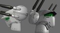
Thanks! And Thanks to all of you folks for all the support. Art doesn't have much of a point unless it is shared, and I really appreciate having such a great group of Macross fans and experts who share this common passion. I've become very accustomed to the process of other artists seeing my works progress in a professional environment, and the constant critique that comes along with that. There's no better group in the world to share this particular project with. I haven't shown Jason any of this stuff yet, though I do recall that he was pushing me to take a stab at a "high poly" valk when we last worked together more than a decade ago. His model was just starting out back then. I'll show him when it is all done. I've been making plenty of progress with the chest block over the last week, but it certainly is proving to be frustrating. When you look at all the toys and transformable models, and every other CG model I have seen, there is a much higher degree of compromise to the original designs here than any other part of the VF-1. This has always frustrated me, and is a big part of what I hope to improve upon. The thing is, the designs are just plain faulty here, and require a lot of that "anime magic" to work like they are supposed to. There are a few things I've managed to work out so far that I haven't seen done before, but I'm finding there are still major parts that need to be done just like all the other interpretations (and not like the lineart has always shown). I'm mentally trying to get over some of these compromises, after doing my due diligence to find solutions. One solution I am pleased with is this: Those shoulder lights can never be quite as big as they are often drawn, simply because they would not fit under the chest in fighter mode. They can't recess into the back because the wings hinge directly beneath them. They are considerably reduced in size on every transformable toy and model for this reason. Also, all the toys and models just leave an open slot in the top of the chest to accomodate them. Some CG models have added a sliding panel that would open up to accomodate them, but I dislike this solution. Fortunately, I managed to keep the lights decently big on my model (and still leave enough clearance to detail them just like this drawing), and worked it out so that panel (outlined in green) can hinge out of the way for it in fighter. The biggest problem area is the shoulder hinge itself: This hinge defines the proportions of the battroid torso, and it isn't as simple as all the designs make it seem. I really wish it could look exactly like this drawing, but it just isn't possible for a number of reasons. If it were that wide (extending all the way to the shoulder), the front corner would have to stick out of the chest in fighter since the chest is angled. It also isn't leaving any space for the fairings on the underside of the chest and back either. Those fairings seem to just disappear in all the original lineart designs, and they are considerably reduced in size on all the toys and transformable models (or even just left out altogether in some cases). The Hasegawa 1/48 model has the largest underside fairings I've ever seen, and it looks really great in fighter, but they just can't actually be that big (it would push the chest and back too far apart in battroid). I've decided to model them as large as they are typically shown in the fighter lineart, but not reduced as much as they generally are in the toys. I'm folding in a portion of the fairings on the back piece to accomodate the arms. That TanJ guy did this as well on his model, but there are actually panel lines in the original designs that work well for this that he didn't choose to follow. I explored a number of schemes to fold away the chest portions of the fairings as well, but nothing really worked. The main problem is that the LERX needs to fit inside these on the chest in batttroid. The toys got around this by reducing the fairings dramatically in size, so that the LERX portion of the fairings ends up outside of the reduced chest fairings. Thankfully, I was able to size the fairings where they are right about the "correct" size, and the LERX will still fit inside of them in battroid. Ultimately, the portions of those underside fairings at the shoulders have to be visible, and the shoulder hinge panel needs to be narrowed to accomodate them (like all the other toys and models). On top of that, the panel needs to be much longer (front to back in battroid) than these designs always show. They are especially long on the transformable toys, which makes the battroid chests too long (front to back). I came up with a slighly more complicated hinge system that minimizes how much this panel needs to be lengthend. It is still longer than shown in this drawing, but short enough to pull together the chest and back to the minimum distance (so that the wings will be just behind the bottom of the nose in battroid). The problem here is that hinge size is no longer long enough to gap the distance required for fighter. The solution is that the internal portion of the LERX (that the hinge attaches to) needs a sliding extension piece that extends the hinge to fit in fighter. Fortunately, that works quite well. I also ended up starting over from scratch on the LERX, and made them much beefier than I had them before. This actually made them look much closer to how they appear in one of my favorite of the DYRL drawings (the one currently in my avatar), and it also helps with the proportions of the Hasegawa 1/48 (where the legs are lowered in fighter to give them the nice size for battroid while keeping them nice and straight vs. their angled interpretation on the old 1/72 models) as it takes up the space they added between the LERX and the intakes. Most importantly, it allows much needed room for the leg transformation mechanism, which I am now much more confident about. There seems to be plenty of space there now, and I should be able to avoid ending up with parts that look rediculously too thin there. I'm still experimenting with space for the battroid side covers. That's going to be a real trick to pull off well (which is why most interpretations just ignore them completely). Hopefully I can make that work decently. Any reference you guys might have would be greatly appreciated. I see practically nothing of it in any of the original lineart that I have.
-
Thanks! Believe me, I'm in the same boat as much as any of us. I would LOVE to make that work somehow, and it pains me as I get deeper into the model to see the feasibility of it lessen. It could be made to work, but the compromises to the design as we know it pile up to the point where it wouldn't be worth it. Things like the back of the nose/head cavity/neck surface are ambiguous enough in the designs (or lacking altogether) that I could get away with pushing the details and proportions around to work. The cockpit (especially in fighter) have been covered so well in the designs that those details are much more "set in stone", and I would see it as the bigger failure to compromise any of that. Here's a couple of images I just tossed together to help illustrate the issues involved: As you can see here, the space is packed full. There is barely any clearance anywhere. I color-coded the parts so we can see what's going on. Blue is the cockpit tub, the landing gear bay is green, and the head cavity is red. That box behind the seat is what would have to magically come apart and become the battroid screens and controls that surround the seat in battroid mode (despite NONE of the details matching anything shown in the battroid cockpit designs). Let's say we go ahead and compromise that. Now, for the seat egress, there needs to be a hole in the cockipt tub (covered up by the box) for the seat (and the pilot, and the armrests!) to move through. As you can see, there's not remotely enough space, even for just the seat. You can also see that there's no straight path for it either. It isn't like it can just go straight up (up in battroid). It would have to go through the landing gear bay (which is why they did that weird thing in the VF-1 Master Files). Even if the landing gear bay magically got out of the way, we now need to squeeze the seat (+ pilot and armrests) through that head cavity. The outer opening is barely big enough, but it is much too small on the inside where there would have to be some opening for the seat to come through. Then we start to consider the smaller details... The armrests are a great example here. The fighter cockpit designs show the armrests as part of the cockpit tub, with mechanisms underneath to raise and angle them up with the seat in battroid. The seat designs also show the seat as being separate from the armrests. Then, in the seat egress drawing, we see the armrests somehow go up and out with the seat. This is why the VF-1 Master File redesigned the seat with the armrests attached to the seat, and that design looks kinda cool, but it isn't the seat that Kawamori designed anymore, and it compromises the whole fighter cockpit that was originally designed as well. That whole VF-1 Master File battroid cockpit transformation scheme, illustrates just how impossible the whole idea is. They had to redesign everything, and go as far as moving the entire landing gear bay outside of the nose in battroid to make it kinda work. I'm happy to see that they explored the idea and came up with solutions, but it also just shows me how much compromise is needed, and that destroys the whole design for me. Nothing weird about that! I've spent hundreds of hours on this, and I feel the same way all the time. I can manipulate the model on my dual 24" monitors all day, but I can't hold it in my hands! It makes me really wish I had some experience with 3d printing, and I've built the majority of it with that in mind, spending a lot of extra time to create "water-tight" geometry, neatly quadrangulate and triangulate everything, and at least planning for stuff like back-faces for hollow and separate parts. I know there were a lot of limitations like that in the past at least, but I'm not even sure what the limitations are these days. In any event, it wouldn't be that much trouble to boolean in the details that are currently separate in some areas, if needed. I would LOVE to eventually get a physical model out of this. I believe we live just a couple of blocks from each other, too. We should totally collaborate on something like that, if you're interested.
-
This was discussed in more detail earlier in the thread, but I don't plan on trying to make a tranformable cockpit. I absolutely love the DYRL battroid cockpit, but there's just too much "anime magic" involved to make it actually work in 3d. The seat is built so the headrest can pivot into battroid position, and it wouldn't be much trouble to add the mechanisms to raise the armrests and controls to the battroid position. The problems are all the battroid screens (with additional controls attached to them) that come out of nowhere to surround the seat. The box behind the seat and the front console would have to be re-designed to make them open up and have that stuff come out and somehow be able to maneuver into position. I'd rather have a fighter cockpit that is accurate to all the designs vs. a fan-designed cockpit compromised for the transformation. What I probably will do is just make a separate battroid cockpit, accurate to the detailed DYRL designs, that can be switched out with the fighter cockpit. I'd rather forget about showing an impossible transformation, and just have individually accurate fighter and battroid cockpits. Thanks!
-
From the album: DYRL VF-1 WIP
© Dan Bickell 2012
-
From the album: DYRL VF-1 WIP
© Dan Bickell 2012
-
From the album: DYRL VF-1 WIP
© Dan Bickell 2012
-
From the album: DYRL VF-1 WIP
© Dan Bickell 2012
-
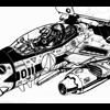
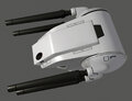
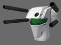
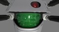
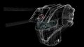
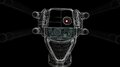
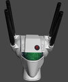
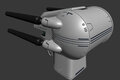
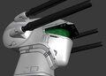
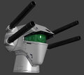
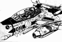
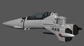
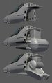
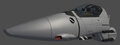
Ok, so the nose section is finally complete, after all this time, with the head transformation mechanism. There is very little lineart reference for what this area looks like, so I did the best I could to incorporate the available details and make it all work at the same time. These are the primary references used: Of course, this is a VF-1D, so the proportions don't quite work for the other VF-1 models. Also, that block sticking out doesn't work (or make sense) at all, even for the VF-1D. I think it was just a device thrown together for that one scene in the TV show, so I ignored it and replaced it with a transformation mechanism to move the heads around where they need to go. The head cavity itself has tricky clearance issues, barely clearing the landing gear bay and cockpit tub, with just enough space for either head (properly tucked in). The other major reference is this one again: As much as I love this drawing, it does have some problems, mostly to do with the seat raising battroid egress (which I grow even more confident that it won't ever work without seriously compromising the design), and the scale of the head (too small here, especially given the perspective). I borrowed as much detail as I could for the head base platform, re-arranged a bit for clearance issues (inside the chest, directly underneath the air-brake in fighter). So, here are the results: The transformation mechanism is most similar to the Yamato 1/60 V2 setup, but with the one pivot offset (puts the base platform lower adding clearance for the heat shield and air-brake under the chest) and a sliding mechanism added (the longer A head needs different positioning in fighter). You might notice that this also fixes the problem with the heads sitting a bit too far to the rear in battroid on the Yamato. Perspective makes the heads look a little big in these shots, but they are matched up nicely with both the Hasegawa 1/48 plans and the Yamato 1/60 V2s. This shot shows it better (but you have to use your imagination for the rest of the battroids, of course): I also did a little re-work on the rest of the nose, to bring it up to current specs. The panel line cross-sections and materials have been matched up to the style I used for the S head, and I added a couple of little details that have been bugging me: I'm excited to finally be able to move back to the chest block. There's some exciting DYRL-specific stuff there (exciting to me, anyway) that I haven't seen others do yet, and I've had a bit of an epiphany about how I'm going to go about the LERX and their part in the leg transformation mechanism, and it actually comes from my all-time favorite of the DYRL detail drawings. Fun times ahead!
-
Yeah, that is not Jason, though I have looked at that guys work before. This TanJ guy is in Japan, where Jason lives up in Washington. He did some interesting things with the transformation mechanics, and got some great details in there. I have some of his images amongst my references already, and find it useful both for things I do and don't want to do with my model. The trouble with the transformation mechanics of the chest block is mostly just space and clearance issues. I spent all day yesterday doing a new back of the nose/head cavity and head transformation mechanism. When working out the chest/back/LERX, I immediately started running into clearance issues with the original head transformation mechanism and head cavity at the back of the nose that I originally blocked-out. The head transformation parts needed the space for the air-brake, and there was no room in between for the heat shield to fit anywhere. I started over from scratch on those parts, and now I have something that not only works much better (puts the head in all the correct positions, with room for the air-brake and the heat shield), but looks quite close to the original line art and designs. I'm about 90% done on the detailing, so I should have an update to post soon. The next tricks will be splitting up the LERX to pivot the legs down to the nose, and finding space for the piston actuators to do that. I'm also trying my best to to have the top of the battroid chest block be as filled-in and detail-correct as possible, which has it's own problems. I don't want to cheat things like TanJ did, with holes for the shoulder lights with retractable covers. I have another idea for that, but it complicates things and requires taking up more space. I don't want to do things like move the shoulder-top verniers to another position that makes things easier. Ideally, I'd like to do the battroid side covers as well, though I'm really not sure where those are going to fit. Yeah, the rest of the VF-1 will be a piece of cake! Thanks guys, I really appreciate the support! I'll be back soon with some updates...
-
Don't worry, it will certainly keep going. I've got a free day to work on it today too, so hopefully I'll have an update to show soon. I think we have a bit of language barrier happening here. I'm not sure what you mean by "3d Line Chart"... There are a couple of wireframe renders of the VF-1S on the previous page in this thread, if that's what you mean. I would be happy to render out some more, if anybody wants them. As far as the materials I'm using in 3ds Max, it is currently a multi/sub-object material with 17 Arch & Design Mental Ray materials to get all the different colors, shading, and reflection. For the wireframe renders, I use a copy of that multi/sub-object material with all 17 sub-materials replaced with a standard basic Max material with the same color as the corresponding material, using Blinn shader and with "Wire" checked under the Shader parameters. Of course, these materials are only temporary. They are useful for visualizing the colors and seeing how the geometry shades, and I will use them as the base to bake down textures from once everything is built. That's where all the paint scheme, markings, and weathering will come in. I will likely add subtle normal map effects like waves and scratches in the metal, small rivets/panel fasteners, etc.
-
Sorry to tease so much! I could just work in secret, and eventually just show up with the finished product, but I do enjoy going through it all slowly, piece by piece, and discussing it all. Have no fear, though. I'm working out the head transformation parts and back of the nose/head cavity at the moment. Once that is worked out to my satisfaction, I can resume work on the chest and back. The upper torso is the trickiest part, because of the transformation. I really want to make as much of the transmormation mechanisms work right as possible. The rest will be a piece of cake, and should go fairly quickly. Certain areas might take a little time to detail, but it is all pretty straight forward.
-
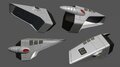
Thanks. I totally get it, and there seems to be a lot of people in that same camp of preferring the original TV designs. It certainly seems that quite a number of people at least prefer the TV SDF-1. In some ways, I tend to be a bit nostaligic about the TV designs as well. If Yamato were to make a 1/3000 TV Macross that was comparable to their DYRL Macross, I would certainly buy it up. I'm not sure that I would choose the TV if I could only have one or the other, though. It would be a tough call, for me. They updated and detailed out the designs when they made DYRL for good reasons. They needed more mature designs, with a detail level suitable for the big screen. In a lot of ways, they overshot the mark, and the detail they added never even actually made it into the movie animation. The VF-1S head is a great example of this, since we never really get those close-ups that would show the detail. Other than a bit of the revised proportions and shape, it hardly looks much different from how it was drawn in the TV animation most of the time. I think that's why we don't really see the toys and model kits differentiating between the two. They all fall somewhere in the middle, picking and choosing which shape and which details to mash together. Making a 3d model with a high level of detail presents the same sort of necessity for the higher detail level, which is a big part of why I chose to do the DYRL VF-1 in the first place. I still remember how much my mind was blown when I first got my gold book, as a teenager back in the mid 80s. That detail drawing of the VF-1S head just spoke to me, and helped to make the Macross mecha much closer to "real", much like the re-designed hands (that were a much more mechanically sound design). I hope to eventually do the TV version as well, and ideally I would re-do as much of it as I can possibly justify. It's a funny thing though, trying to compare all the original lineart, the re-designs, and what the animators actually drew in either the TV show or the movie. Nothing really matches the others all that well. For me, the original lineart is the most important, as it represents what Kawamori intended. Everything else is only an interpretation, much like my model. Here's a little study I threw together, comparing my model placed with similar angles and perspective to the original TV lineart: Of course, those drawings, as cool and iconic as they may be, are still just drawings. The shapes, angles, and perspective are never perfect, and a single 3d model can never really match up with them. That head-on angle on the bottom right, for example... you shouldn't be able to see the neck rings. They would have to be wider than the head, rather than a bridge between the smaller neck and the bigger head. But it looks cool! To actually try to match a model to the TV lineart, it would have to be very soft and rounded. I've seen some models try to do this, and it works much better for lineart than it does for a 3d model of mecha, at least in my opinion. The other thing I was experimenting with there was the smaller size, since on an image of the complete VF-1S, the head would actually take up a much smaller piece of the image. In theory, the small details should start to disappear as you get farther away, or in shadows, or with motion blur. The end result should look a step or two closer to the lineart depictions, as opposed to the big close-ups of just the head. All this subjective stuff, clashing with mechanical design and realism... I guess that's why they call us artists, right?
-
From the album: DYRL VF-1 WIP
© Dan Bickell 2012