
logan_4600
-
Posts
62 -
Joined
-
Last visited
Content Type
Profiles
Forums
Events
Gallery
Posts posted by logan_4600
-
-
Is it me? or everyone in here, in one way o another knows something about programming and/or cg/3d, etc. ?
-
Nope, I'm using some plastic models for reference but didn't find top or botton views (Only front and side schematics)
Ameo! Tenés la macross enciclopedia de Mr. March! tenés BOCHA de fotos y eschematics de todos los angulos ahi!
Ts: My friend! Check out Mr. March´s Macross Mecha Manual!

-
ajajaa, hay varios argentos, si si... republica separatista , me meo....
Si pueden agreguen la FanPage de Facebook que desde ahí voy posteando links e info que podemos discutir en castellano como nos gusta aca mismo

Me pasas el link porfa asi lo agrego?
-
Hola Gente! Hace unos añitos ando pro acá y nunca me presenté ( ni me di cuenta que habia un par mas de compatriotas ) Saludos desde la república separatista de Chacarita!
-
Logan they are very crampt when it comes to internal space. Even the engine bay is tightly packed. when we remove or install an engine we have maybe 1/4 to 1/2 inch of clearance on either side of the engine for the GE engines. On the P&W engine you can almost stick your head between the sidewall and the engine (which is great when you are hooking up the stage 7 and 13 ECS ducts). The cockpit is so small that when the seat is fully raised you can see the top of the pilot's or brake riders knees with the canopy closed!
I noticed the VF-0 is far bigger, mainly since it has to carry a traditional jet fuel load internally. This required the frame and wings to be bigger. Also one more thing jet engines are not "tuned". They are trimmed. In the case of the EGF-129 the engine is trimmed to the highest thrust rating it can give. This is usually done on the engine through the DEC or DEEC (Digital Engine Control/ Digital Electronic Engine Control).
There´s a lot of technical lenguage i will have to look up there!
Thank you for such a great insightOn other things; the hole cockpit/gear bay DID work without any ´cheat´, maybe some tweaks on the back/torso; now, the arms got me scratching my head, the closest iv´e got from the attaached line art is this ( pay atention to the support of the shoulders )
I think it can share the rotation axis-gear of the wings, or somethings like that...

-
I don't disagree. It was a spur of the moment thought. Though I tend to opt for additional complexity in my implementations. I know it sounds counter-intuitive, but I like to add back in the complexity I imagine the designers removed for the sake of making a line-art drawing. Sort of like a not-so-crazy version of what they did for Transformers when they made the move, though with minimum cheating. (I think they cheated a LOT with those transformations, but they just did it so well it is hard to see. I'd LOVE to take a closer look at one of those rigs). There is a point where additional complexity adds realism IMO. Once you pass that, it's just silly, such as in Transformers, but bumping it up a bit makes me happy.
Thanks, feel free to use it. I'm not at this point in my re-build, but I might look into it again when I am.
To get a bit back on topic about the seat movement and pilot clearance, I'm a big believer in trying to use one big cheat to solve multiple problems. You HAVE to cheat somewhere, and a good option is to slightly scale up the whole aircraft. This makes a bit more room in the cockpit for pilot clearance, as well as more space for a realistic number of controls. I guess it all depends on what you're building your model for. CIG? Cheat your ass off. Video games? Maybe a bit less. 3D printing? You're screwed.
I have this love/hate relationship with movie Transformers, you know, i think the 1st one had some of the very best CG i´ve had seen, the mechs not only are there, they feel like they ARE there. But the transformation system? pfsss... like you said, pure cheat. It has no logic or mechanic accuracy. Hated that.
I really would love to do some kind of fan made movie. I loved what my countrymem did with Valkyre Project (sad is the outcome it had with all the linceces issues) but, it felt way off the Macross spirit. Very much more Robotech and Western.
Either way, right know i am still learning, had to turn down SDF1 for that reason. But, i if i think about it, i am modelling things that i don´t even know i will use/show or not. This is accuracy for fun, and learning.
I just did some comparisons for measurement. These are the Height, length, winspans for other aircraft along with the VF-1. All in all it is a very strange aircraft size wise.
F-14- Height 16 ft, length 62.9 ft, winspan (fully extended) 64ft, weight 43,735 lbs unloaded
F-16- height 16 ft, length 49.5 ft, winspan 29 ft, weight 18,000 lbs unloaded
VF-1- height 12.6 ft, length 46.69 ft, wingspan 48.49 ft (fully extended?), weight 37,000 lbs unloaded
here is the kicker!
F-5- height 13.4 ft, length 47.4 ft, wingspan 26.8 ft, weight 9,558 lbs unloaded
I work on F-16's and to comprehend an aircraft like the VF-1 being actually shorter in both length and height is odd to me. F-16's are tiny compared to both the Tomcat and Eagle, but it is about a foot shorter than the F-5 which is one of the smallest jet fighters built.
You work on F-16´s??? .... like... inside them!? o_0
PS: If you look it up, the VF-0 (a craft i LOVE) is wat WAY bigger than the VF-1
-
I've always felt all of the head laser barrels need to be able to retract quite a bit to make quick and easy clearance during transformation to Battroid. In most cases, spinning things around just right will allow them to clear, but it would make sens to get as much clearance as possible.
Seeing as how the barrel doesn't need to contain expanding gas (like a gun barrel) I think you could get away with something like this, and still have clean lines when extended. Obviously I didn't spend much time on this (to function, I'd expect a second inner barrel and something to keep everything on track).

Really cool idea!!! when i was messing around with full transformation in previous versions (with both ´torso` parts and all that) the lasers where a real trouble. Had to sync very carefouly the keyframes to make everything work well. Now, this idea is just great.
To be honest I see the head laser momentarily moving out of the way of the bay doors & gear easy enough to be believable. It doesn't necessarily mean it would be unlocked as it could have multiple locking points or it could simply return to its original position after the doors open and the gear extends. The head laser is designed to move during combat anyways so I think the addition of a telescopic laser barrel just wouldn't be necessary.
I always thought that the lasers were able to rotate and stop at any point ( like that, even in fighter mode you can aim like what, 60 degrees? ) very usefull
-
Great observation. In my case is a Vf-1s, so, The laser is not in the way. Either way, for a Vf-1a is not a lot what it has to rotate to make room.The only real world penalty I can think of would be the fact you don't want a turret unlocked on your landing approach. The drag induced by normal pylons loaded asymmetrically is very noticeable on a fighter to the pilot. I also know from watching DYRL that the head turret has to actually lower itself to unlock and swivel. It would take a wind tunnel to ascertain what the drag effect would be with the head turret being unlocked and swiveled either left or right on landing.
-
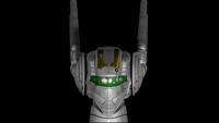
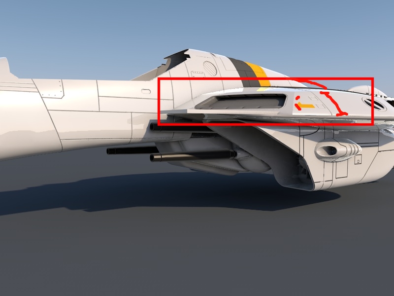
Yes march! got them (from your site
) I never got to get what part or what is that thing in the upper right corner form the first image. -
Nice!!! And thank you for link, i will read up as soon as i can!Logan_4600 - have a read maybe this will make sense
Anyway an update
( this thing of 'learn trough The process' can get tiresome )
-
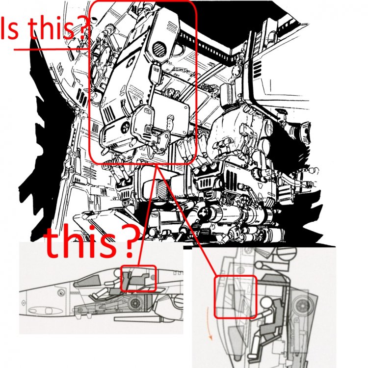
Ok! So, we all agree with the schematics for The transformaton. But, seen al the feedback, the gear bay is big. ( i did model it taking The size from the master file pic ). Making it smaller is a benefit. Also, The pilot is oversized too.( And that is something to keep un mind to ).
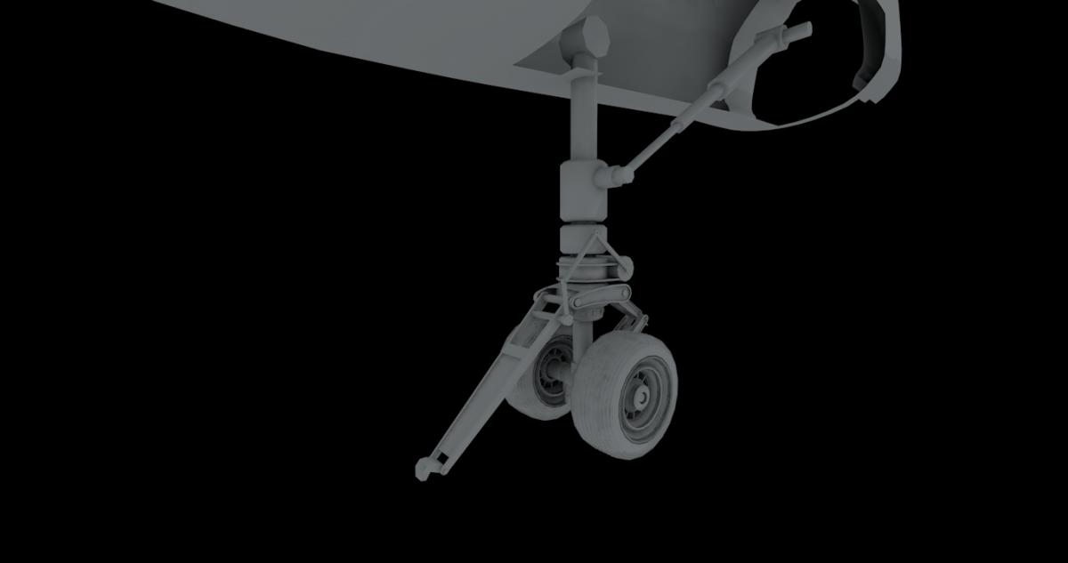
Yes! The barrel is in the way, but there is one pic showing that it rotates to make room!Also the nose tire looks to be out of proportion also. Typically fighter nose tires tend to be smaller than that. Even when it is a double tire like the F-18 or F-14 would use. Even most nose tires on these aircraft tend to be around a foot and half in diameter or a little wider than the human head. That angle box section of the nose well could be reduced in size when the tire is proportioned correctly and more than likely the only area raised to allow for the torque links to fit would be directly over them. You would be shocked at the amount of space that can be utilized in a well engineered wheel well. I also just noticed something amiss in the lower 2 diagrams, mainly the left one. The barrel for the laser on the A model VF-1 would be in the way of the nose gear as it extends. I would also suspect that the strut would work better for landings if it was mounted the other way. With the trunnion pin being mounted to the rear of the well and the nose tire being in the front of the well when it is retracted. Just give an idea of what a modern fighter wheel well looks like here is a link with walk around photos of an F-16.
http://www.aircraftresourcecenter.com/awa01/001-100/awa002-F-16C/00c.shtm
So... Tryin to wrap up, smaller front gear, and, that box IS the secondary control. Are there any pics with more references of it?
-
But, they make sense. If not, The front landing gear shuould be way farther from The cockpit to make some room for the pilot seat to rotate.
I did re watch the first and second episodes from Macross and it makes sense. ( other VFs in other series are simpler tough )
-
I get what you say. Looks like the pilot and/or The seat should be smaller.
-
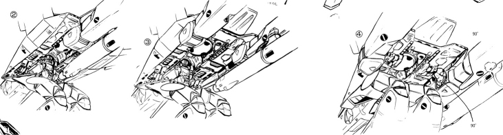
Ook! This going somewhere. The gear sholud not be getting down, but, its just to show you it does move too!
You have the seat getting in position, and the head too. Also the fron gear bay goes down to make the space (in this vid, the full nose and the actual cage / bay are absent )
-
Guys! That pic is actually in this forum! Is from the book series Variable Fighter Master File. (im trying to see if a can get one of those books) You can find them here http://www.macrossworld.com/mwf/index.php?showtopic=34651&page=5
So, what do you say? is that accurate?
I have seen those smaller diagrams before with the seating position and landing gear box extended to make room for the pilot seat rotation.
The top illustration I've seen also but does seem a little spacious than you'd expect. In reality it would be somewhat cramped.
Hooo yeah! I´m having a VERY hard time with my CG VF triying to make everything work mechanically accurate, and then have the space that the pics shows. Some things when you start wroking them just, doesn´t seem to work well.
Where was the second one at? It looks like a toy or model manual or something. The top one is rather common (as Macross goes), but yeah, it looks a wee bit spacious for sure. Though it would be hard to show all those details without it being GoPro like. The cockpit transformation discrepancies are one of my biggest issues with the VF1. I think the YF19 and others had it right. Just tilt the seat back!
Yes, also the VF-0 acctually making the seat AND instrumental rotate seems more logic. But, if the VF-1 is like that... well... i will model it like that!
-
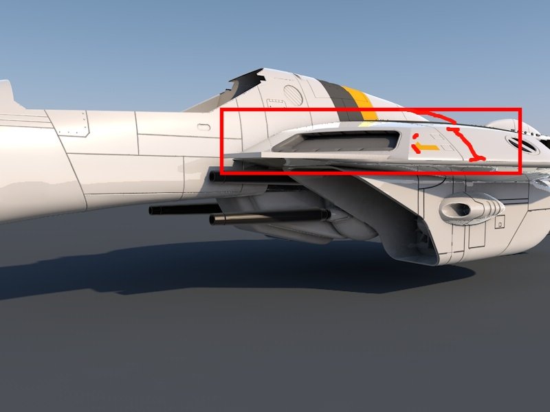
Hi Guys! the picture says it all
-
Logan_4600 - Not sure my methods would help , I use Rhino which is a pure nurbs modeller , each surface is constructed using curves and filleted and trimmed for detail each panel was detailed on it's own . I believe you use blender -totally different approach with polygons , you shape and sculpt .
What helped a lot was , I got lot of info from guys building kits , they take good pictures and that model is nearly 10 years old .... today I would have done it differently . I have been tempted to update .. but first finish my VF-19, if I ever finish all my "side" projects
Yes! The site is filled with great references, even from fan works! I use Cinema 4D ( Nevermore was the one using blender ), and i DO rely a lot on NUrbs (now called Subdivision Surface). And, i did it two o three times. from a Square, from a Lofted Spline, and i can´t get yet the curves there right! (or the overall form ) I even don´t really like how it outcomes with any technique... it´s just... not "slick"...
You seem to get all the curves and form just right!
( This ones... )
-
checking the fit ...
Nice work! Can i ask you how did you aproach the "torso" ? ( you know, the double chest front and back parts)
-
Dude! Nice!
-
Jeez Dude, very very sweet!
-
Looks Awesome!!!
I was doing an SDF-1 (http://www.macrossworld.com/mwf/index.php?showtopic=40367&page=2 ) but ended beign too big for a starter, so went the VF-1s way. ( http://www.macrossworld.com/mwf/index.php?showtopic=40367&page=3 )
Are you planning on making it fully transformable? (or mechanically accurate?) i´m getting very frustated with the authenticity of the transformation system :/
-
Oook!!! I know it´s not much; but i´ve spend the time actually ( learning to, and ) fully riggin it!

-
A good resume they have!
From recent movies i love the CG work on District 9, Battle Los Angeles, The Machine (some LOVELEY work there).... hmmm... and surely a lot more, but with that "less is more" feel. (and I have to be honest, ILM in the first transformers is absolutley astonishing too ) -
Thank you spanner! i really don´t know if i´ll be able to keep up the pace, but i will try to post the wip´s more often.

South Ataria in FSX
in Fan Works
Posted
Hahaah that's SO true! ( goshhh how i enjoyed Frontier !!! )
You know, i think i'll start a thread about this, so se can help each other and share knowledge!