

MMORefugee
-
Posts
28 -
Joined
-
Last visited
Content Type
Profiles
Forums
Events
Gallery
Posts posted by MMORefugee
-
-
Salt masking can be a lot of work, but it's the best way to get that faded paint look on carrier-based aircraft like the VF-0. It's also great for rust. Here's the first kit I tried it on:


-
My 0D, which I got from HLJ, has the misaligned intake markings as well. That being said, I'm not bothered by it for a couple reasons. First, my 0D is otherwise fine. No missing, loose, or damaged parts. Secondly, the misalignment is pretty subtle and I didn't even notice it until it was pointed out on these boards. The markings aren't misaligned with respect to the intake edges, they're misaligned with respect to each other. Since they're on opposite sides of the aircraft, you'll never be able to see both of them at the same time.
-
Agreed about the weathering, the exhaust from the backpack boosters in particular. I also really like the green tone you used on the gunpod.
-
Did anybody review this thing? I don't think I saw any reviews yet.
Graham
-
I'm psyched to finally get a 0S. The first release had been discontinued before I got into valk collecting, and I'm not about to pay an inflated price for a toy of dubious quality.
Hopefully we'll get an improved SV-51 down the line as well. I really want an Ivanov, but again, the same logic prevents me from getting one of the originals.
-
Have you tried something like Mr. Surfacer 1200 thinned with a lacquer thinner?
I've had good results with Mr. Finishing Surfacer 1500 thinned with Mr. Color leveling thinner.
Tamiya tape, the only way to mask.
Agreed. The blue 3M masking tape is pretty good, too.
-
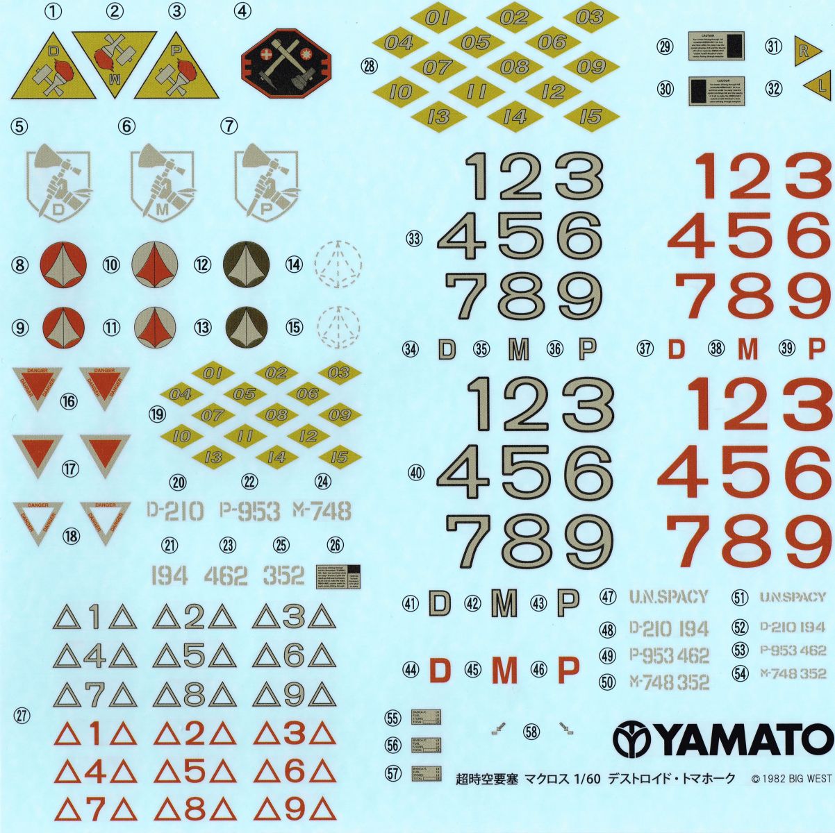
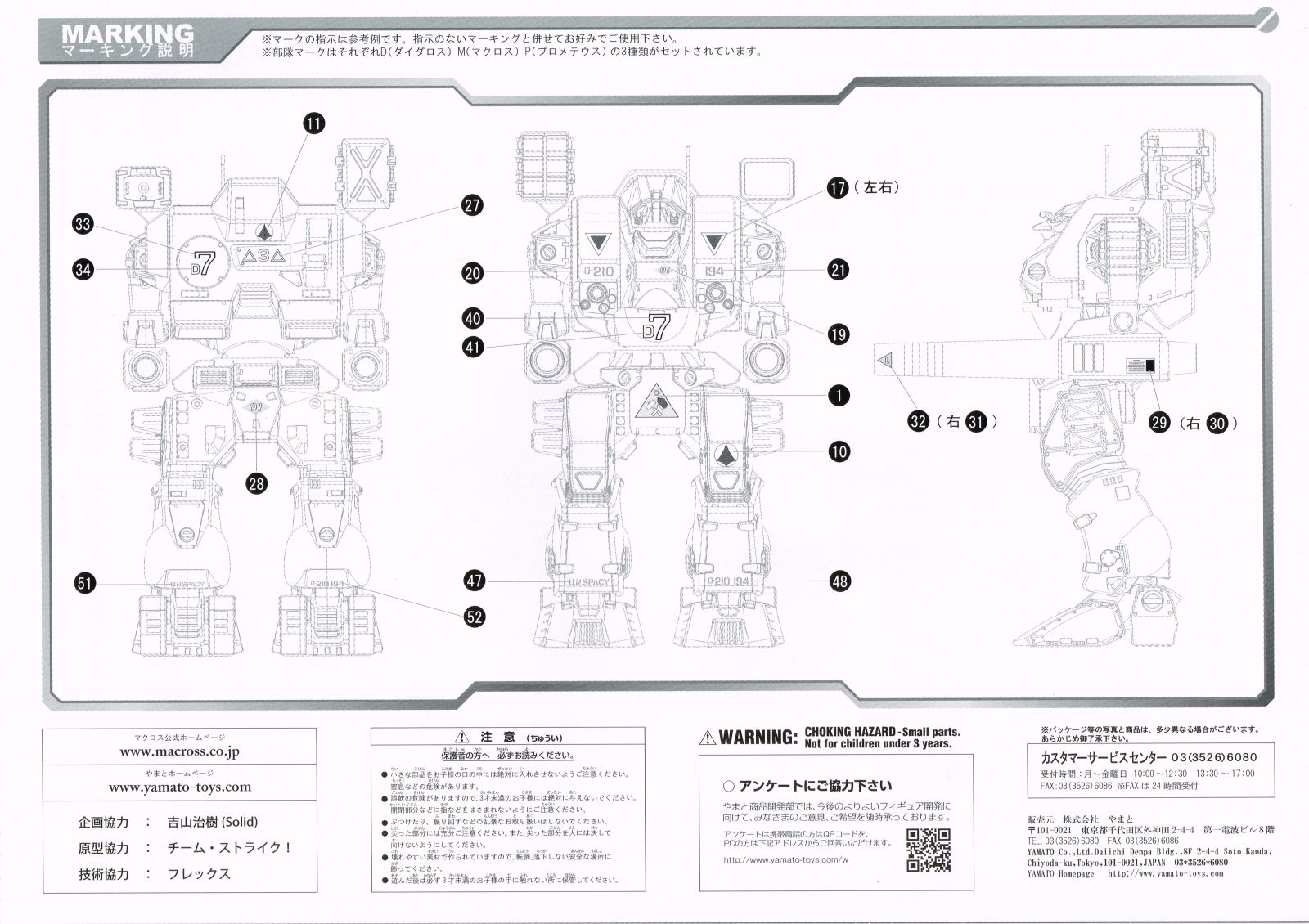
I'm making a wild guess here: The ship to which the destroid is assigned. Daedalus, Macross, or Prometheus.
-
What I have just shows the markings as "L" or "R" on their respective sides. I guess destroid pilots and ground crew have trouble telling left from right.
-
A few stray thoughts:
The VF-1 doesn't carry fuel, exactly, but it does use reaction mass while flying in space. From a control management standpoint it could behave the same way.
The keypad on the right side panel reminds me of a KNS-660 FMS (which I've actually used) or the ICP on an F-16 (which I've only seen pictures of). I'd imagine it's alphanumeric, like the keypad on a phone, and can be used for data entry in any system, controlled by a rotary switch or selector buttons or something.
The screen directly below the primary flight display looks like an FMS display. Alternatively, since there don't seem to be any standby flight instruments on the panel, that screen could fill that function.
I'd imagine the most practical approach would be to come up with a list of controls that you'd need to operate an aircraft like the Valkyrie, and then start installing them on the panel. Keep in mind that systems tend to be grouped together. All of the lights will be next to each other. All of the radio controls will be next to each other, and so on. Since the VF-1 is a nuclear powered aerospacecraft, it won't be exactly the same as a modern aircraft, but will still have some analogous controls. One example I can think of is firewall shutoff valves and fire extinguishers. You could instead have "Emergency Reactor Shutdown" handles or similar.
-
As far as the markings on the panel go, the best diagrams I've seen are on Mr. March's site, the Macross Mecha Manual (http://macross2.net/m3/m3.html). His site is an all around great resource.
This drawing in particular, http://macross2.net/m3/macrossdyrl/vf-1a-fastpack/vf-1-dyrl-cockpit-instrumentpanel.gif is probably closest to what you're looking for. It looks like a scan from page 043 of the Variable Fighter Master File: VF-1 Valkyrie (http://www.hlj.com/product/SOF35182/Sci). If that's the case, then you're pretty much on your own for coming up with panel markings. I had a close look at my VF Master File book and the markings are nonsense, saying things like "may the force be with you".
Since you're experienced designing aircraft controls, it's probably better that you set up the panel yourself anyway. You could try basing it on the panel of an F-14, the aircraft which inspired the design of the VF-1.
-
I personally favor the DYRL cockpit. It's a more modern design, with a more sensible HOTAS control scheme. Subsequent variable fighter types from later series use the DYRL style control layout as well.
I followed the link to your website and had a look at some of the products. Holy cow, those are some nice looking quadrants. I've spent my fair share of time in the Lear 45 and I recognized those thrust levers before I even read the description.
-
This thread + this (http://www.macrossworld.com/mwf/index.php?showtopic=41219) thread = win.
-
I might have to get one of these. Do we know if they'll come with Roy and/or Max markings also?
-
While prowling various model building forums I saw people mention something called "watch crystal cement" to glue transparent parts. Anyone have any experience with this?
Also, on the subject of aircraft canopies, anyone know a good way to get that gold tint?
Like this:

-
The DYRL cockpit doesn't have a HUD combiner above the glareshield, just those two mirrors. Macross Mecha Manual (http://www.macross2.net/m3/m3.html) is a fantastic reference source.
Specifically: http://www.macross2.net/m3/macrossdyrl/vf-1a-fastpack/vf-1-dyrl-cockpit1.gif, http://www.macross2.net/m3/macrossdyrl/vf-1a-fastpack/vf-1-dyrl-cockpit2.gif show the cockpit quite clearly.
I bow before your detail work on that pilot. Also, shaping the arm retention tabs so that the legs sit square in fighter mode is absolutely brilliant in its simplicity.
-
Mr Color has a brand of thinners and retarders, which you need to use if you're going to paint with them. Vallejo is also a very good brush painting paint, which you might want to look at.
Mr.Color sells something called leveling thinner, which is a premixed bottle of thinner and retarder. Works beautifully with Mr. Color paints.
-
Tracking shows that my package departed LA customs yesterday afternoon; so here's hoping it'll show up at my door today or tomorrow.
-
This thing has the absolutely most amazing looking fighter mode of any VF, I just had to go for it and order one, even if it ties my personal record for 'most expensive toy'.
As an aside, I think the paint scheme on this VF-4 would look fantastic on a VF-1.
-
There was a similar discussion on this thread: http://www.macrossworld.com/mwf/index.php?showtopic=34651, starting on page 7, regarding the intakes on a VF-1.
The general opinion seems to be this: On a VF-1, the engine is located in the lower leg, below the knee. There's also a fan located in the intake, up in the hip. This fan is presumably electrically driven, and used to maintain smooth airflow to the compressor section of the engine in GERWALK and battroid modes, with the kind of extreme intake geometry that you'd get with the legs bent.
It seems reasonable to assume that the engines of the YF-21 and its derivatives work in a similar way. The main body of the engine is located in the hump at the tail, and the fan up in the intake is there mostly to provide some airflow for the VTOL nozzles in GERWALK mode. To give a real-world example, the F-35B has a lift fan mounted forward of the engine, used for VTOL operation, and shaft driven by the engine to the tune of 28000 horsepower.
That being said, keep up the good work, the YF-21 is one of my favorite VFs.
-
Wow, if 3d printing is that expensive, I guess CNC milling your model from aluminum would be completely out of the question.

Ever since I saw this model, I've been dreaming of seeing a VF-1 get the same treatment:

(Image courtesy http://www.craftsmanshipmuseum.com/)
Seriously, though, maybe you should try hitting up the members for donations. I'd be willing to throw in just to see your model come to life.
-

I was thrilled to see the panel lines in the LERX in this shot. I just know there's a brilliant leg transformation mechanism hidden in there and I'm dying to see it.
-
Generally, in most aircraft, located behind the radar is the avionics bay, which is chock full of bulky electronics. Even if you were to assume a big overtechnology assist to Moore's Law and substantially shrink the avionics, pushing the gear forward conflicts it with the hip pins.
To flog a different deceased equine, I'm on board with Chronocidal with regards to the engine inlets. It would be worthwhile to try a rounded inlet lip with a semicircular cross section. Retain the bulk of the v.1 inlet, but make your airflow happy and laminar, and get rid of those right angles.
-
There's no reason the fan blades couldn't be made to turn their angles. I did a fair amount of research, looking at modern turbojet fans, and I don't recall seeing any with variable pitch blades. They do typically have quite a severe angle, though, and I went with that to limit visibility behind them. Having a single piece fan would also be preferable for any 3D printing (otherwise you're going to need 33 pieces for each fan!).
Those fans are certainly an interesting part of the design, though. Of course, in a real-world turbo jet, those are shaft driven parts of the engines. In the VF-1, it would have to be more like a self-contained electric motor powered by the reactors, just providing airflow in gerwalk or at low speeds.
You're right, most turbine engines generally don't have variable pitch compressor rotors, although variable compressor stators aren't unheard of. While you could feather (which is to say, angle them to a high enough pitch so that they face edge-on into the airflow, contributing neither thrust nor drag, reference multi-engine propeller driven aircraft) the compressor blades in that first engine section, a more practical solution for high speed flight would be to simply bypass it completely. Looking back at the first Master File book (simultaneously a blessing and a curse, those seem to be), that funny "RAM/SCLAM jet mode" illustration on page 080 seems to illustrate just that. It's not apparent from the illustrations, but I'd guess that the intake covers are closed, bypassing the hip/thigh section, and air is entering at some hypothetical inlet in the knees.
The idea of having a motor driving the compressor is actually pretty old. It never caught on, due to being impractical. The amount of horsepower required to drive the compressor depends on the airflow rate, and pressure and temperature increase, but it quickly gets into the thousands or tens of thousands of horsepower. For example, a compressor pumping 100kg of air per second at a total temperature increase of 400C (not unreasonable for a fighter engine like a P&W F100) requires just under 42000 kilowatts, or around 56000 horsepower.
To be fair, this is the kind of power it would take to run the compressor for the main engine section in the lower legs. If all we're trying to do is maintain smooth airflow to prevent compressor stall at the kind of extreme inlet geometry you'd get by embedding a jet engine in your shins, you probably just need enough mass flow to maintain a slightly positive pressure. At this point, though, we're probably overthinking things (reference http://www.theforce.net/swtc/index.html).
That all being said, I absolutely love your work here, and the last thing I want to do is cause any further distraction or delay on your project! I'd be happy to provide any help I could. I have access to business jets and turboprops and can take detail photos of things like brake assemblies, control actuators, light assemblies, that sort of thing. It's not the same as F-14 or F-18 specific material, but still potentially useful as generalized aircraft references.
-
Time for me to stop lurking and start contributing.
1/60 = 5 pcs.
1/48 = 1 pc.
A few notes:
One of my 1/60s is the v2. DYRL Roy VF-1S weathering special, with the weathering special Strike pack. It is a stunningly beautiful piece, which sadly consigns it to be forever displayed in fighter mode, as I'm afraid to transform it and scratch the paint.
On the other hand, my VF-11B has been transformed multiple times and is holding up great.
My lone 1/48 is a DYRL Max 1A, my first Yamato, bought deeply discounted as a way of testing the valk-collecting water. As evidenced by my growing collection of 1/60s (YF-21 just came in the mail today!), the water is just fine.
1/60 Perfect Transform VF-4G Lightning reissue.
in Toys
Posted
Exactly: