

captain america
-
Posts
3464 -
Joined
-
Last visited
Content Type
Profiles
Forums
Events
Gallery
Posts posted by captain america
-
-
next pic
-
next pic
-
next pic
-
next pic
-
next pic
-
My fingertips are thoroughly crazy-glued, I'm zonked on putty fumes and it's been a long week. Time for another update.
Sorry for the poor quality of the pictures; I'm using a webcam whilst I decide on the best digital camera to replace my ill-fated(and crappy) HP unit.
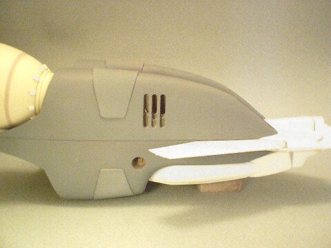
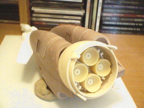
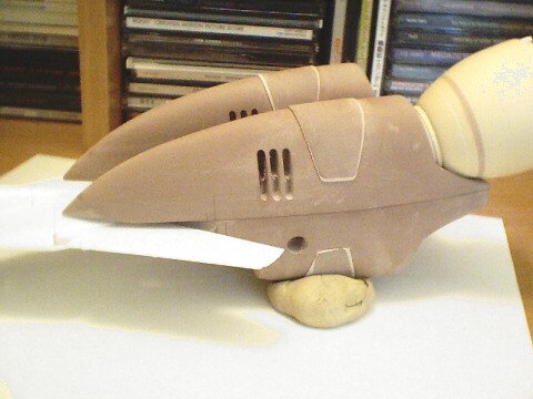
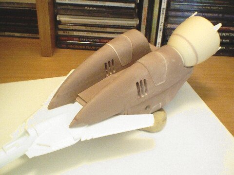
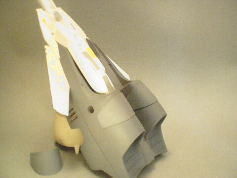
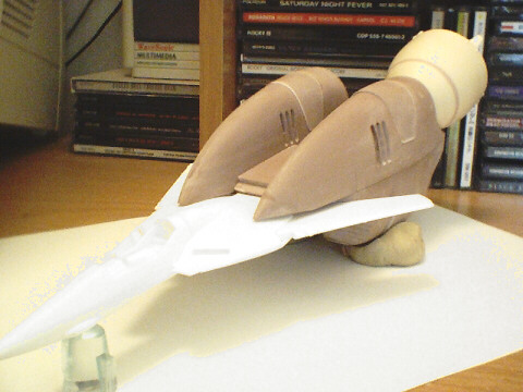
As you can see, I've coated the main hull parts in grey, as they are very nearly complete, with just some surfacing to do before fine-detailing/scribing. In the views of the lower hull, you can clearly see the tapering of the outer hull as it joins to the leg unit. I've left this area rough for now, as I'll have to use the SUPER Valk legs to make the final fit adjustments. If you notice down the center of the lower hull, there are ten circular indentations. These will be for the mounting latches that hold the booster to the launch arm.
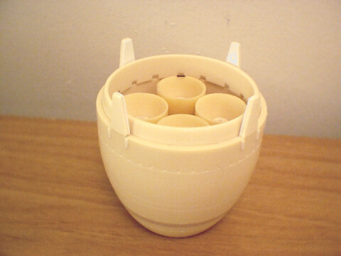
Other views of interest are the rear of the main hull sections where the nozzle mounts. I've added some little bits inside to make these interesting, like the main circular couplings with individually drilled & pressed rivets(even though they'll be all but totally obscured by the nozzle itself.)
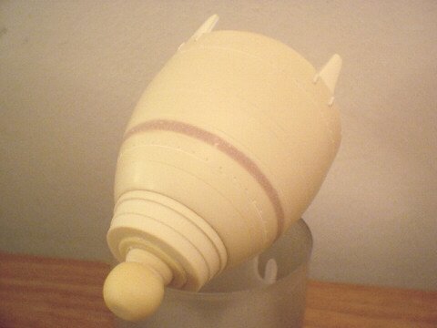
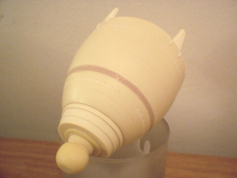
Speaking of the nozzle, the endbell itself is now finished, and decidedly a pain in the ass to photograph... It's dotted with several rings of very tiny rivets that are just too small to capture on cam; only the larger rivets seem to show. Nevertheless, these will be quite the visual treat when seen in person.
That's about all for now; I'm going to put the booster aside temporarily until my Super parts arrive. There's maybe 2-3 days of work to finish it all, so I'm almost there (( your patience is greatly appreciated.))
Cheers,

-
You may call me... Shun Yoshikuni ( fast guy from good fortune country)
Sonds like something I'd get out of a fortune cookie

-
Hi WM.
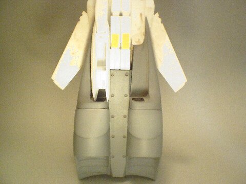
The plan view of the booter was a bit of a compromise as it turns out. When you look at it from 3/4 front/elevated level, like in the main pic, it looks spot-on. However, if you make the booster fuselage TOO bulbous at the mid-section(around the UN kite), you will end up with a tremendous amount of overhang over the legs. If you take your Hasegawa VF-1 kit and look at it from the underside, you see that the legs are actually narrower than the chest/back/main fuselage to begin with, so if you then exaggerate the outward flaring of the booster, you just compond that problem.
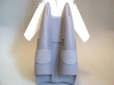
By the way, Kawamori's drawings contradict each other in terms of proportions. In his 3/4 front view and 3/4 underside view, the side bulge is gradual and progressive, whereas in the rear view, the sides of the booster look almost board straight, and then taper in dramatically to tuck-in under the booster nozzles. As a result, it's impossible to get a solid 3-D form to look EXACTLY like all of Kawamori's drawings, but I am keeping it superbly close... And creatively ad-libbing in the grey areas.
Re: teeth details. I'm not sure what you're referring to exactly. I still yet have some little rectangular bits to add to the base of the nozzles... Might those be what you're refering to?
-
Hi Thor.
Quite simply, once the blocks are cut square, I take my trusty ol' dremel and sanding block, and simply hack away at them 'til the shape is right. Lucky for me I have eagle eyes for proportions, so I'm able to keep everything symmetrical to within about half a mm. You can do this too, just be sure that as soon as you carve one curve in one piece, that you immediately cut the same curve in the mirror part. The more closely you work on both parts simultaneously, the better your chances of keeping them symmetrical.
-
Hi Batou.
Actually, Rob is the one handling the marketing aspect of the model, so would be the one to best answer your question regarding price. However, I can assure you that it'll be cheaper than a japanese kit of similar detail/size.
As for the launch vehicle, we both decided that precisely for cost purposes, we would market them as separate kits; basically give people a chance to save-up for them.
-
Hi Valkyrie.
Looks great to me! I'm just coming to realise how tiny 1/72 is; I'm used to working in much larger scales

-
Last pic... For now

-
3 of 4.
-
Pic 2 of 4
-
Hi guys, I'm exhausted... Time for an update
To answer Noyhauser's question, I really don't know, as I don't have a super O kit. It may very well fit with some veeeery minor modification to the center fuselage on the booster. The booster is designed to accept a VF-1 with its backpack deployed "atmospheric" mode and its V-tails flat.
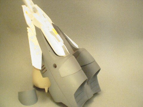
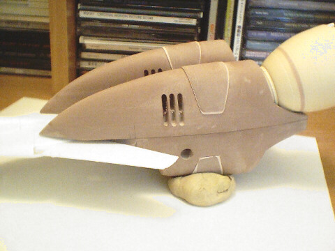
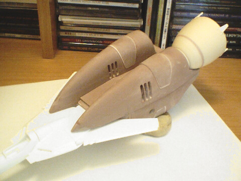
Anyway, onto the pics... As you can see, the once flat blocks of modelling board have now been fleshed-out into a more familiar form. My webcam's lens produces a tremendous fish-eye effect on objects that I shoot from a short distance, and as a result, makes the booster look much more slender than it really is; it's actually spot-on with the side-view Rob posted at the beginning of the thread. All the parts fit perfectly, and tolerances are being kept tight.
As Valkyrie had noticed earlier on, the foreward, upper tips of the booster will need to be cut-back and enlarged... I left them longer for the time being, as I'll need to adjust that entire area to conform precisely to the Hasegawa kit's surface. In a nutshell, things are going exactly as planned.

-
Actually, Gakken DID make a series of 1/12 model kits of the ride-armors (1/12) and Legioss (1/48). They were non-transformable types.
-
Hi Coby.
From what I've seen, the short-term effects of breathing modelling-board dust is quite simply... The sniffles. That's not quite as harmless as it sounds though, as when you blow your nose, you'll see that the stuff accumulates rather fast. Over the long term, you may begin to exhibit breathing problems and/or develop a hacking cough from constant accumulation of dust in your lungs. I see that a lot with veteran model-makers and body-shop workers. There may or may not be other hazzards related to the dust, but personally, I plan to NOt find that out firsthand... I always wear a mask.
Your constant colds may be a result of exposure to chems in the workplace, or, silly as it sounds, you may also have a problem with fungus. Most people worry so much about the industrial-strength goo, that they overlook simple things like mold, that can be every bit as hazzardous if not more so.
-
Hi Sean.
I get my modelling board here
You can work the Ren Shape with any milling machine or lathe, as well as a dremel for removing large volumes. You can then very easily sand it with regular sandpaper for fine finishing. Just so that you know, the dust put off by the material is toxic, so you'll need a mask to work it.
You can get a relatively good finish on the parts, but as it's still technically somewhat porous, you will need to seal it with primer prior to molding.
-
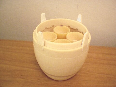
Specialised, yes. Expensive is relative. A 2" by 16" by 50" plank usually runs @ $400 dollars. I'm in Canada though, so we have different pricing. The booster end-bell is actually urethane resin: I poured some into an empty yogurt container and let it harden; makes perfect round stock that you can turn and taper... Just takes way too long to hack Renshape into round bars, so I use it almost exclusively for flats & components that need to be milled.
-
Hi whytwolf.
It's high-density modelling-board: CIBA Ren-shape 460 & 480... 2 inch plank.
-
Hi guys.
Stamen: the side view Rob posted has the little tabs on the nozzles looking chunkier. However, upon closer inspection of the original lineart, Kawamori has them rendered considerably narrower, so I simply opted to stick with the closest reference; I guess it comes down to personal preference with things like that.
WM: the ball-joint will be simply for final positioning/glueing. In reality, you may not have that much positioning leeway as you think, since the nozzle fits quite snugly into the fuselage in the line-art(and probably will in the kit too). The ball-joint will probably end up being just a simple connection point

-
pic 5 of 5
-
pic 4 of 5

-
pic 3 of 5


VF-1 Valkyrie Booster Project 1/72
in Model kits
Posted
next pic