tplayer
-
Posts
43 -
Joined
-
Last visited
Content Type
Profiles
Forums
Events
Gallery
Everything posted by tplayer
-
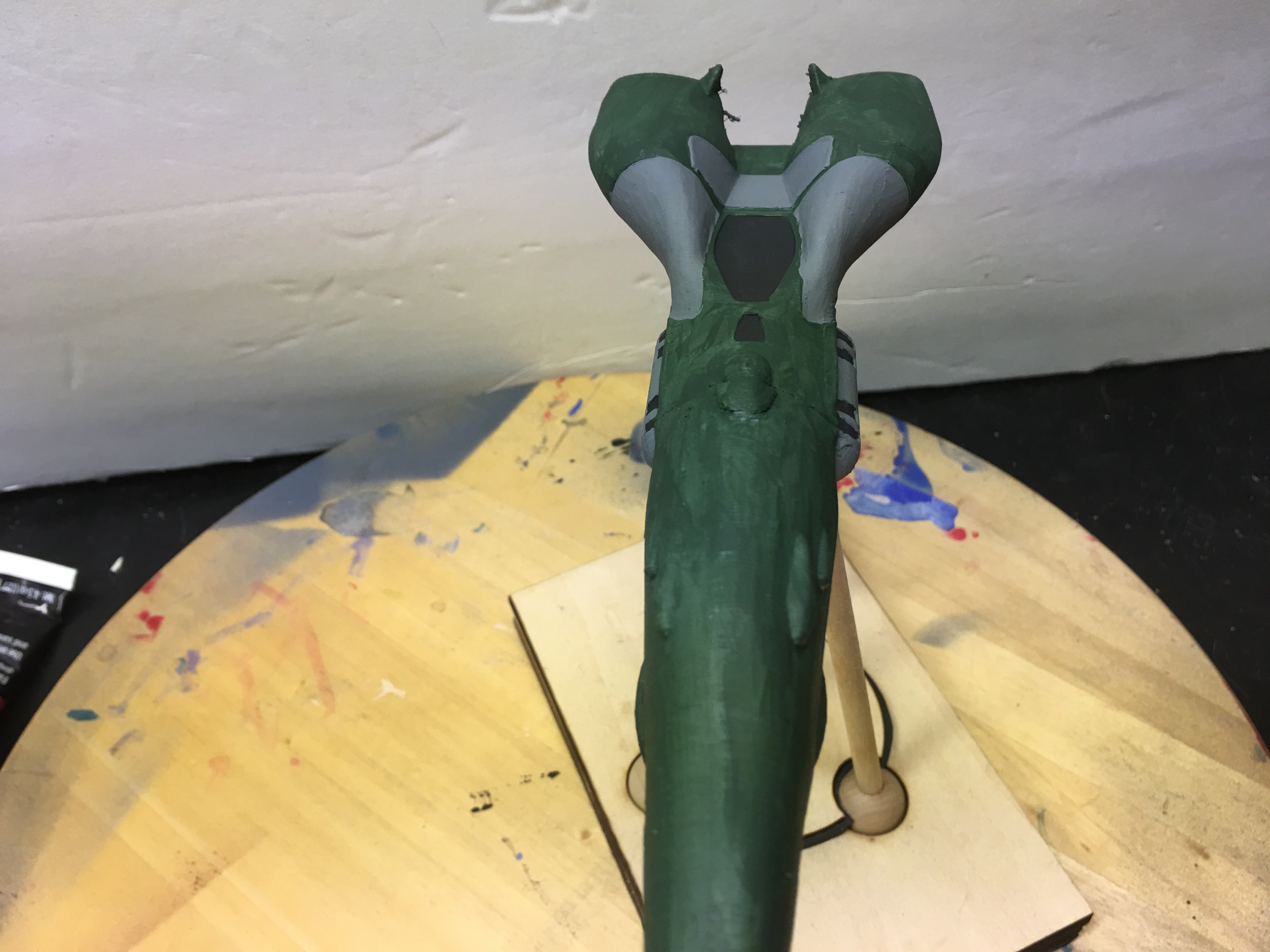
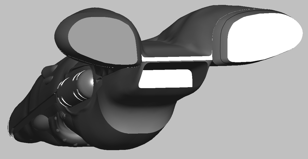
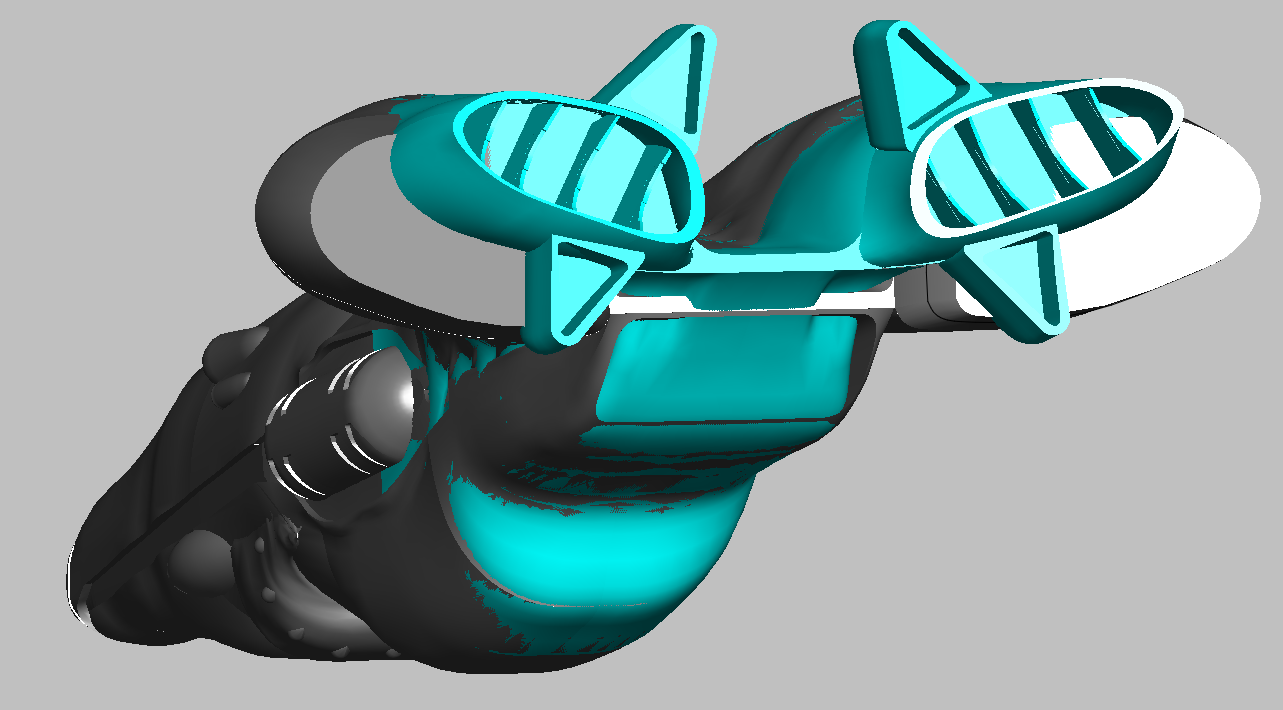
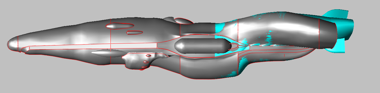
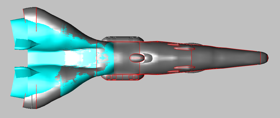
Well, it's been a while since I worked on the scout. I've gone through some life changing events since then and I now have the energy to continue with the build. The pics show the redesign of the rear of the scout. Grey is the new design and cyan is the old. The bay dedicated the width of the engine nacelles The depth of the rear bay will most likely going to be adjusted. The next effort is to work on readjusting all of the parts that were effected by the changes and complete the engines.
-
LOL! I was to quick in my response to your post on the scout topic. I'll have to check out the reference to see how the ships were interpreted from the drawings.
-
Awesome! Another Zentraedi ship build! What scale is your ship? 1/5000? When I get done with the scout, I would definitely do a model swap! Do you have a build log? I would like to see how you approached building your ship. My goal is to build the entire fleet so the next one on the horizon is the destroyer. I'm building a rather large scale so I was thinking of building two scales in parallel: 1/2200 and 1/5000.
-
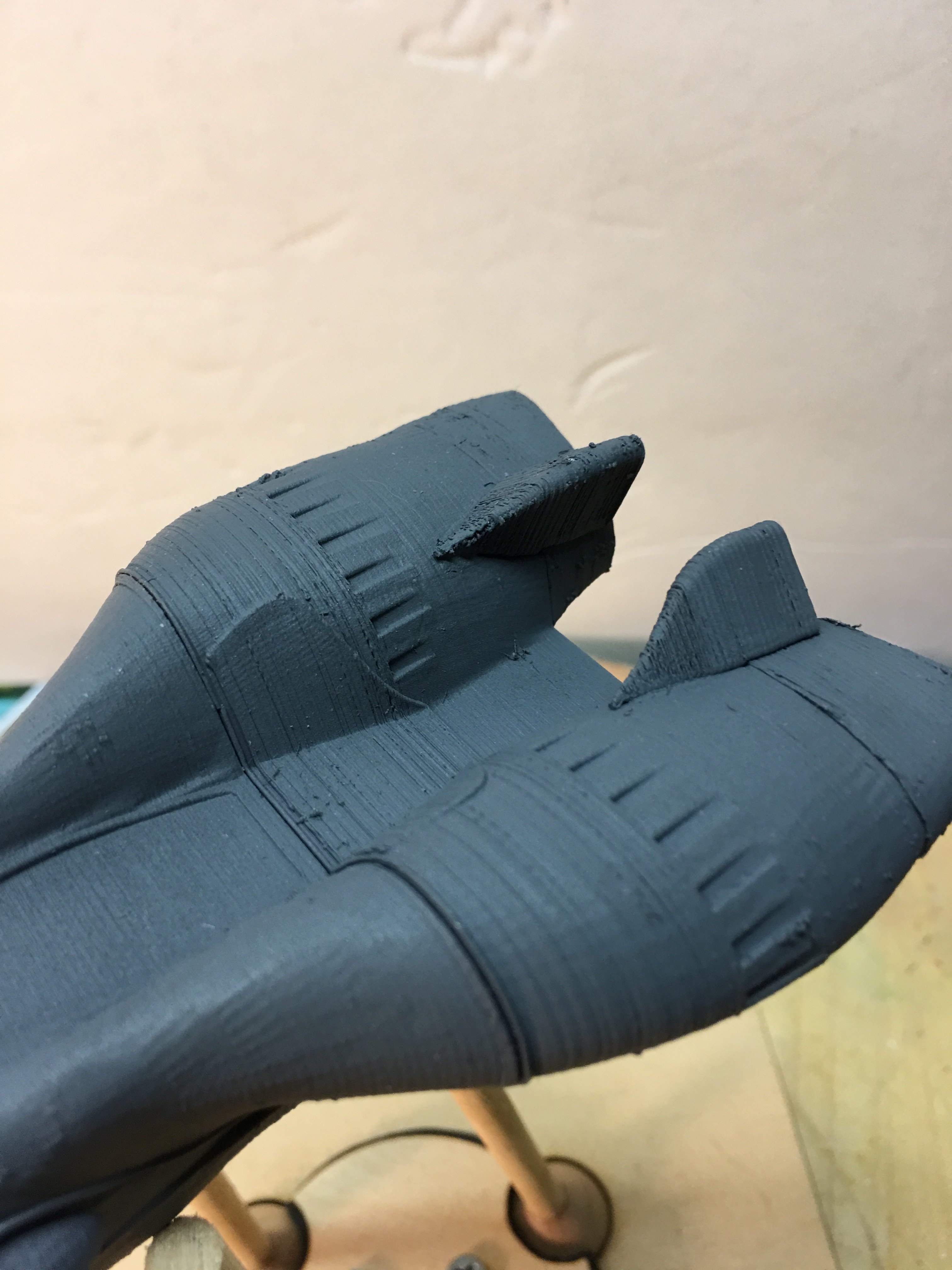
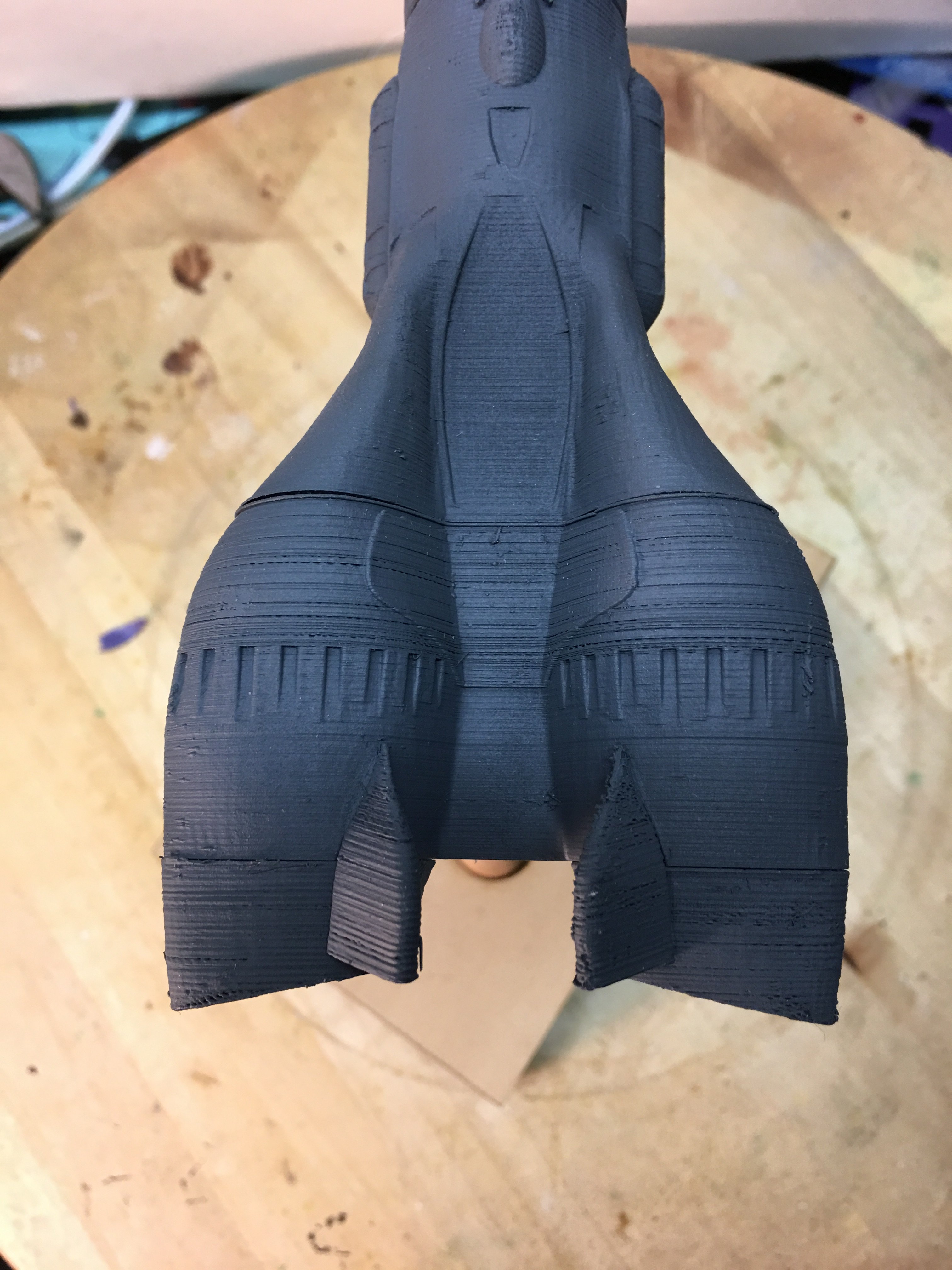
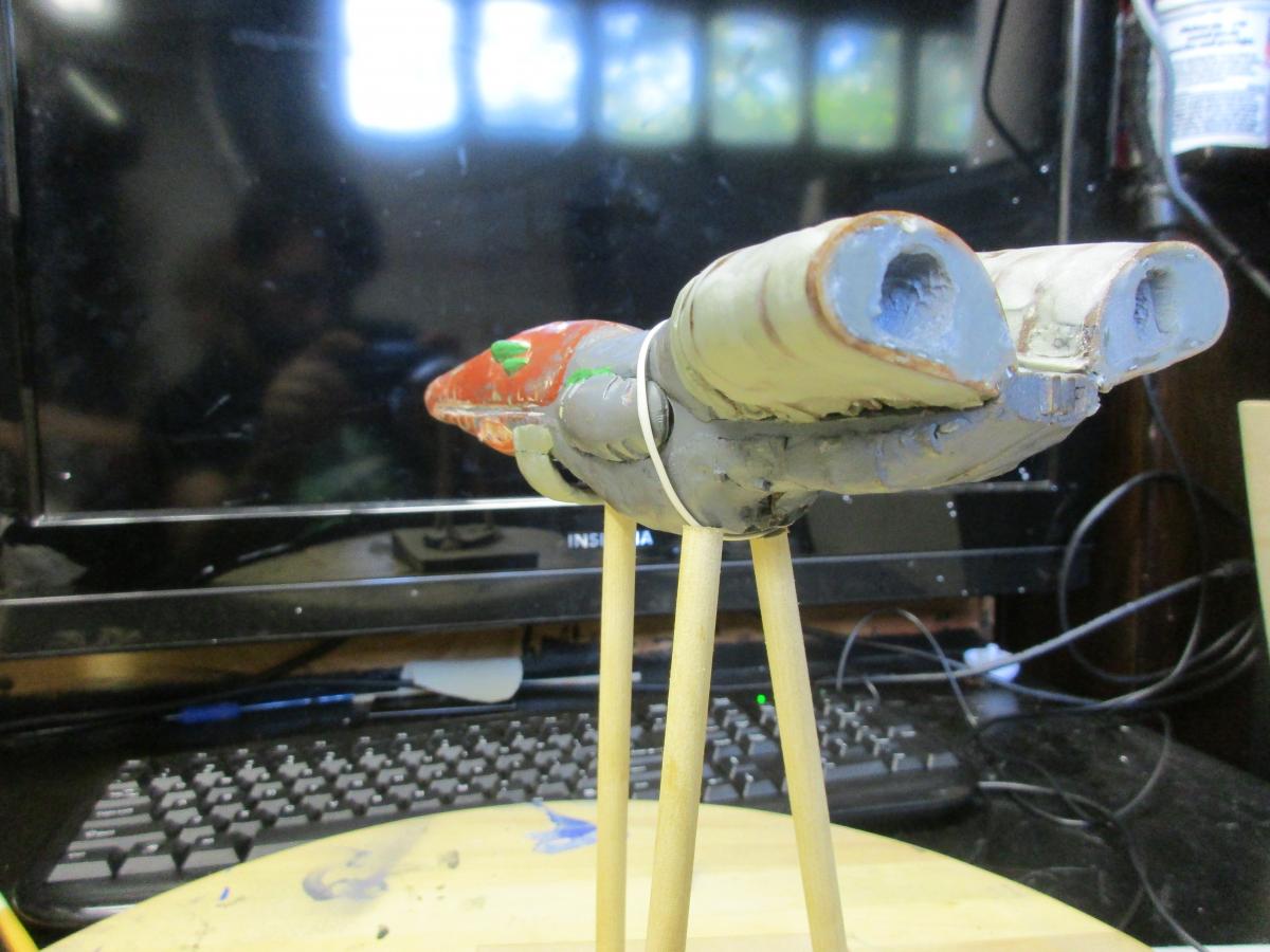
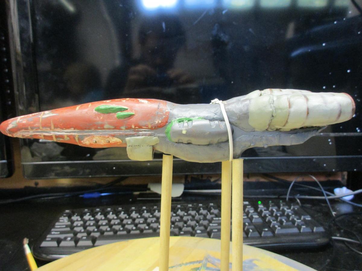
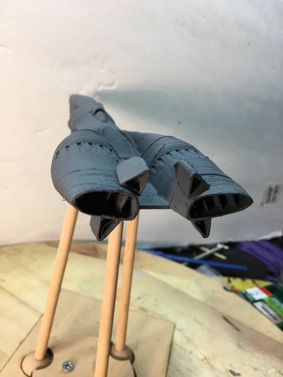
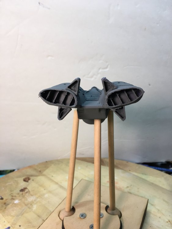
This update shows my progress with the rear of the ship: the notches encompassing the engines, initial shaping of the fins and the engine exhaust. Some of the delay for this post was due to issues with my 3d printer. I managed to get it printing again, but you can see I still have minor issues to resolve. My initial thoughts are I will need to bring out the exhaust vanes, redo how the top and bottom fins attach to the engines, and probably adjust their size as well. From there, I will be concentrating on the rear pod launcher.


-
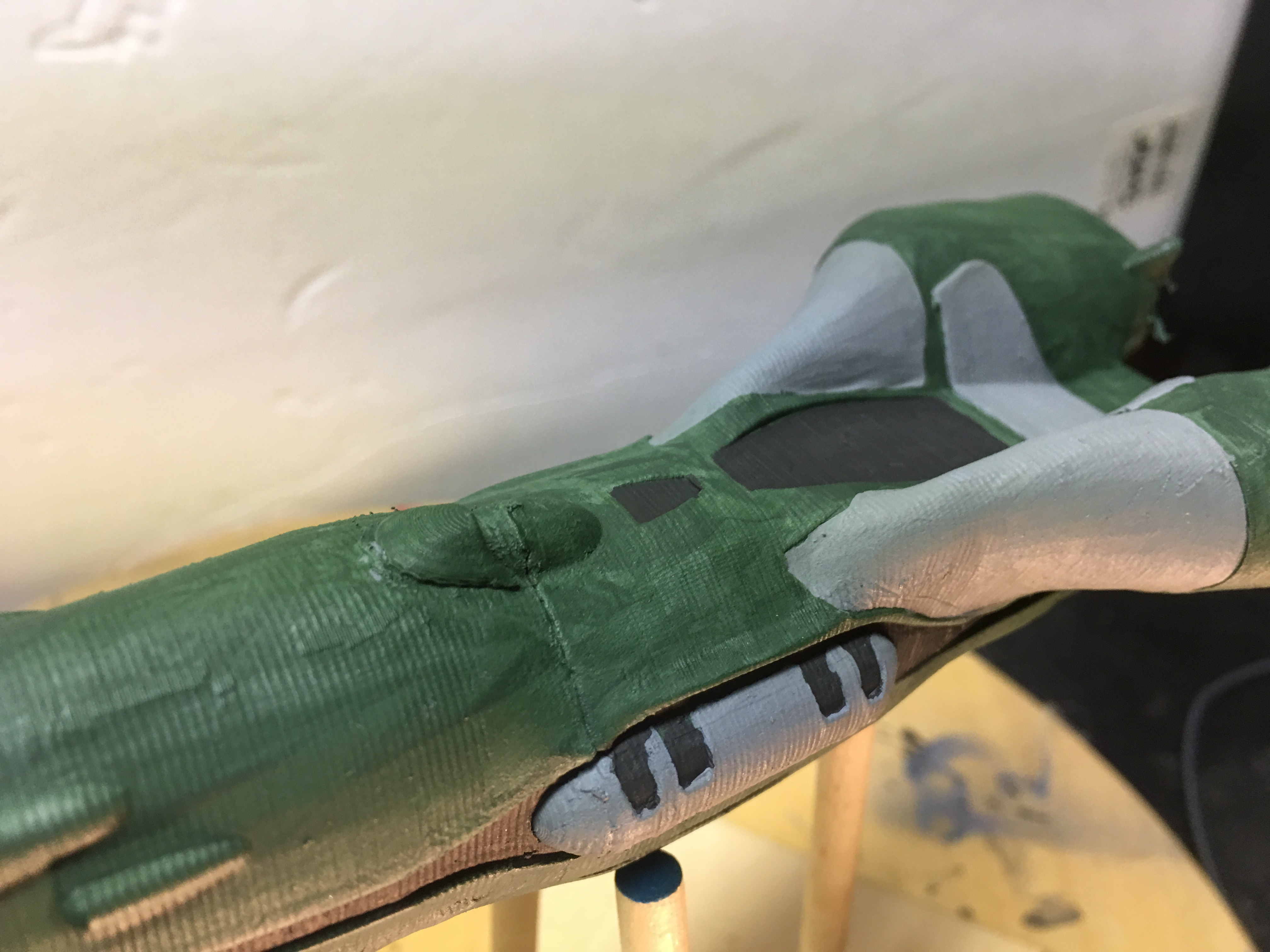
I am glad I didn't give up either. I did have to take a break from the model and then life and other projects kicked in. My CAD skills are slowly improving which is making it easier to get the modeling done. So this post covers what I was able to get done over the weekend: The front engine panels, the top pod, the two major panels, and the "winged" panel between the engines. I will need to indent the front engine panels more to make them more pronounced. Overall, I think I can move onto to the back part of the engines and mainly concentrate on the ribbing that goes along the circumference of the engines and back fins.


-
Wow! Time flies! I'm one less project so I will have more time for the Scout. This post covers the completion of the side channels meeting at the front of the ship and the lower "scoop". I just printed the front half of the ship to save time and plastic. I feel I captured the essences of both from the drawings. So I am now moving top side of the ship to work on the center pod, the paneling, and the engine notches. I'm getting more productive with the CAD software so hopefully the next post won't take 6 months!

-
I have a Monoprice Select Mini. It has worked well for me as a starter printer. At some point, I will need to get or build another printer in order to print larger pieces especially when I start working on the Zentraedi Destroyer.
-
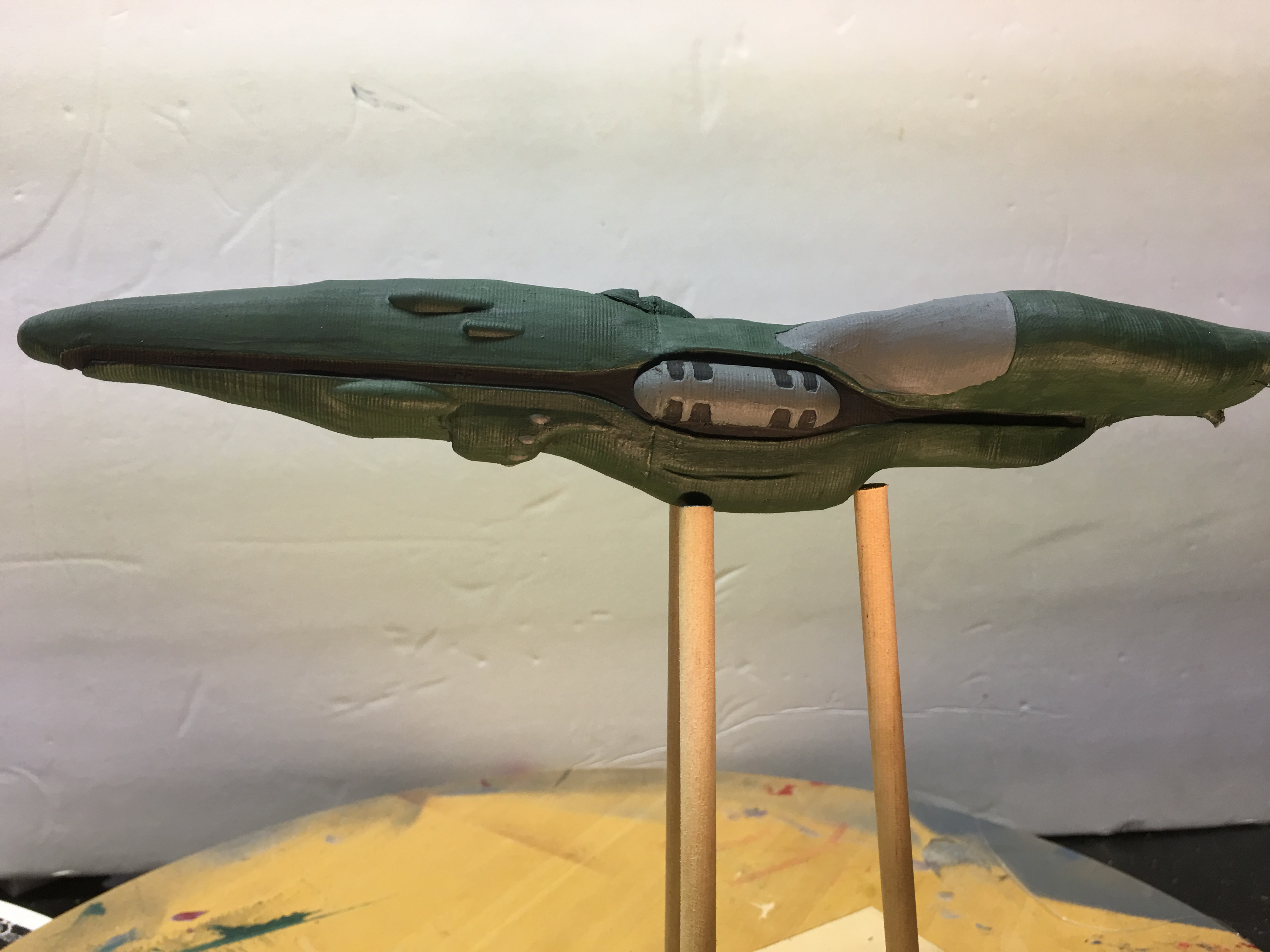
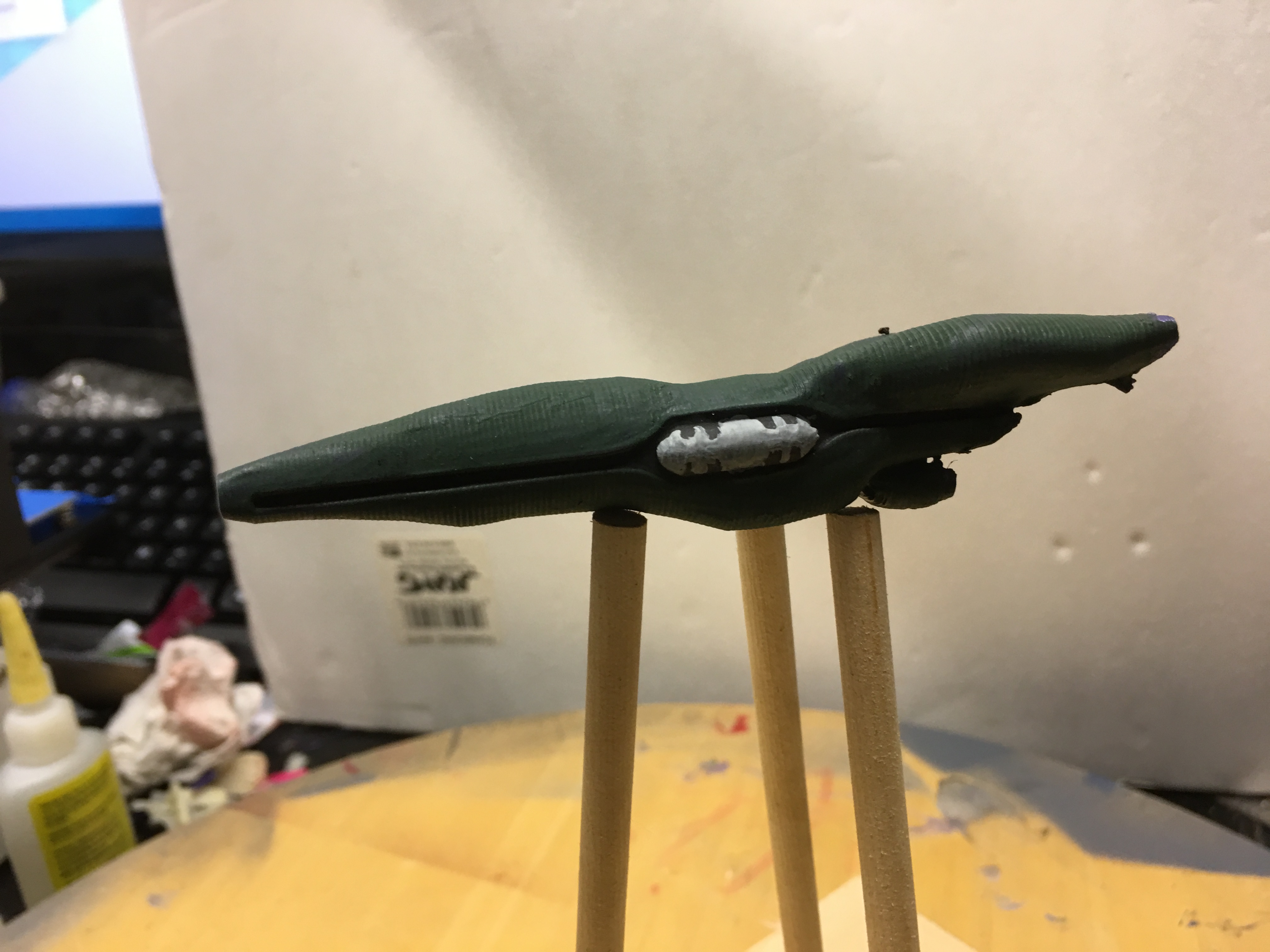
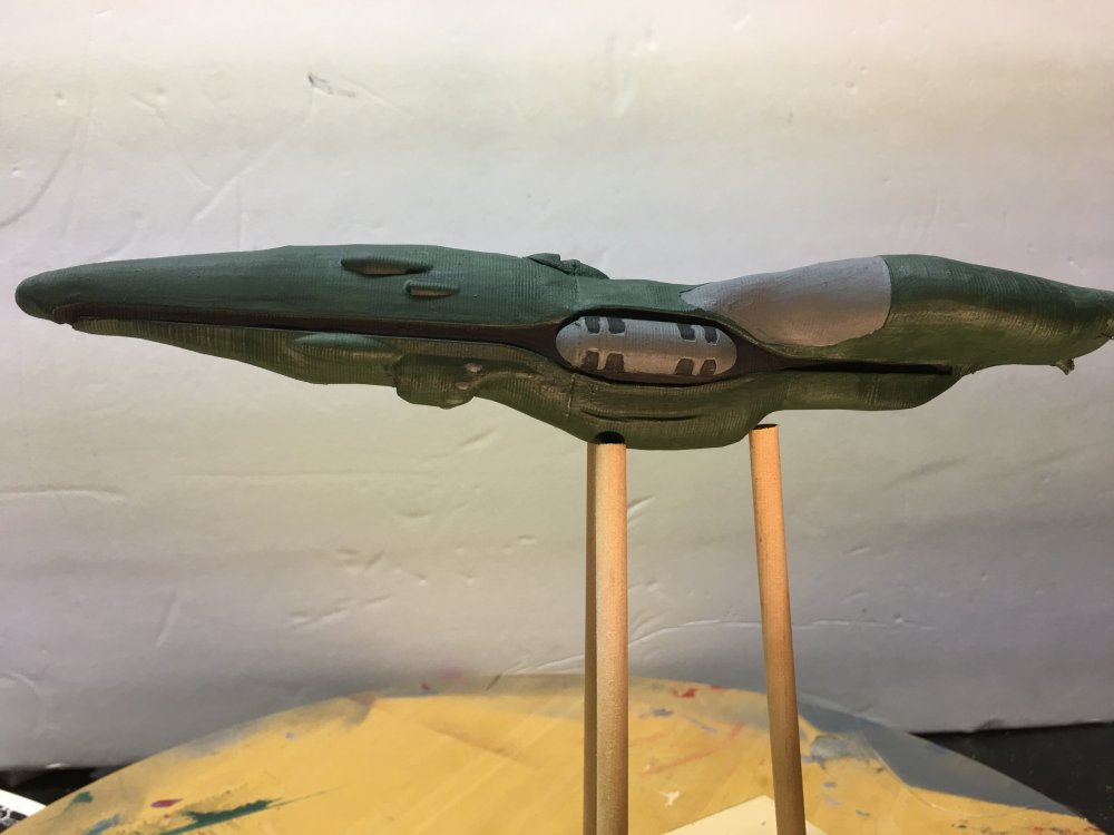
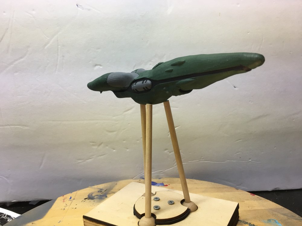
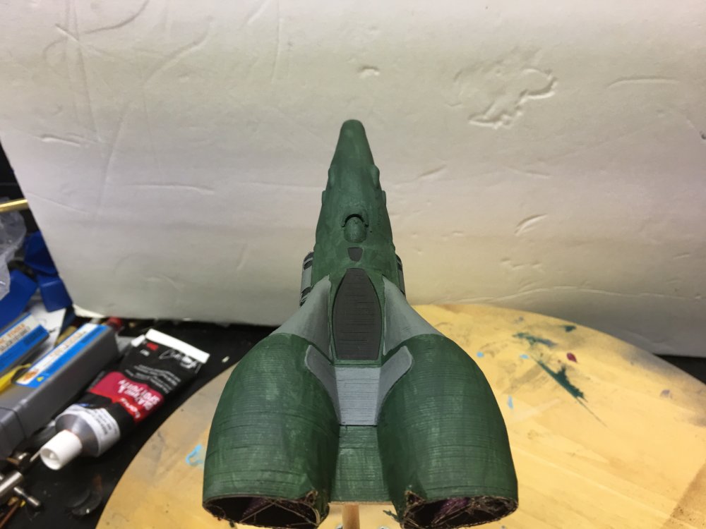
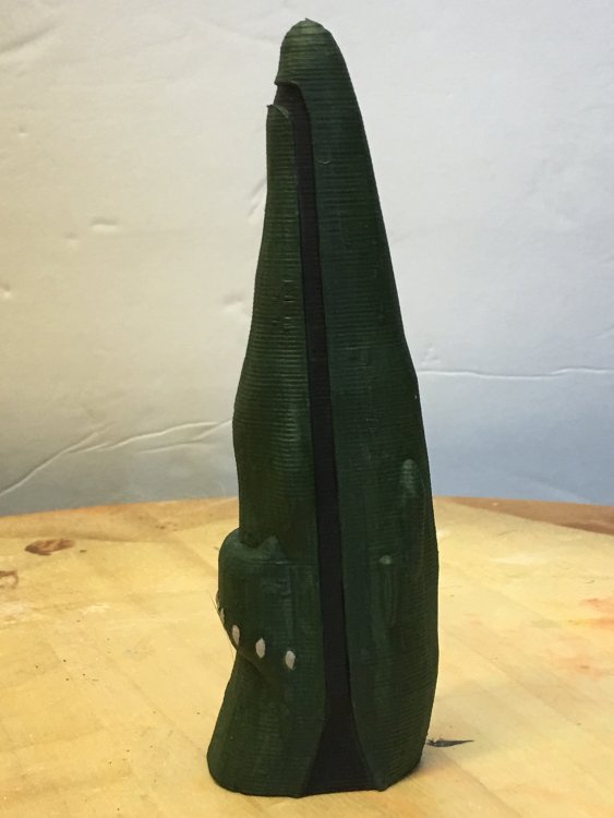
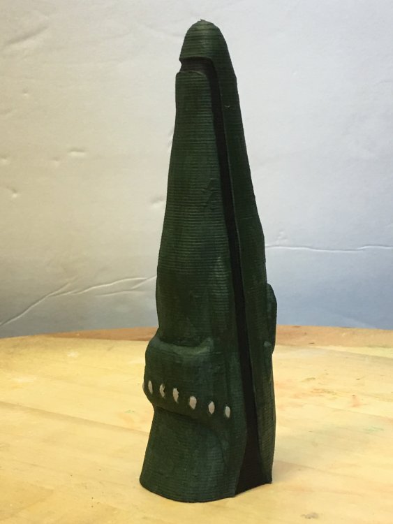
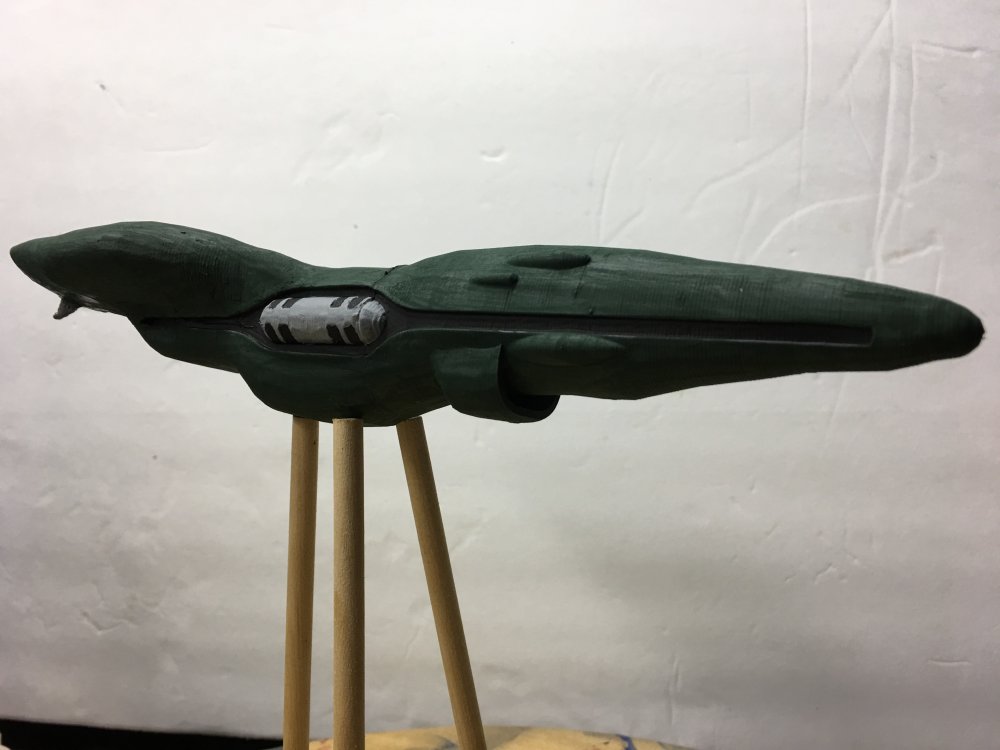
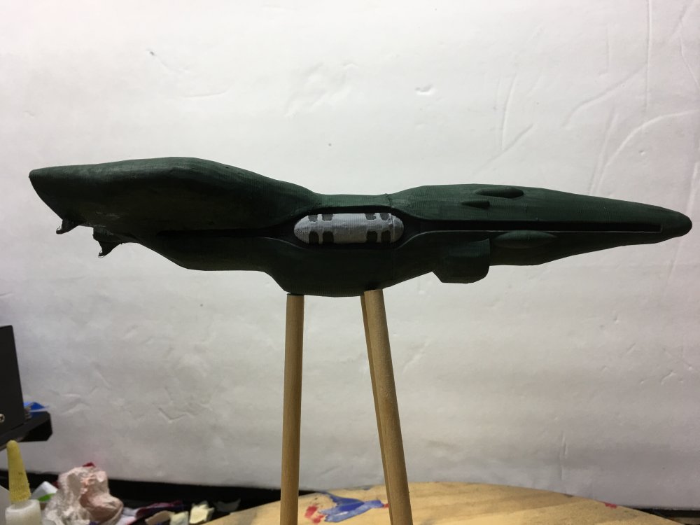
This update is the first full scale print of the scout with a basic paint job. I purposely left out the lower engine and the details of the back since I wanted to see what the front looked like. The scoop needs to be longer but I think the front upper and lower pods are the right size. Modeling the channel near the front of the ship that loops under to the other side has been giving me a hard time. I decided to press forward with the rest of the ship with the hope of getting done later. Plan B is to do it manually. Learning 3d modeling has been steep for me but I know in the end of all this madness it is going to be rewarding! The last picture is a half scale of the whole ship before adding the front pods and scoop.


-
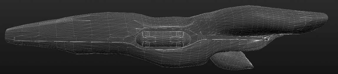
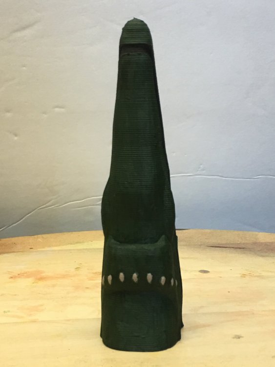
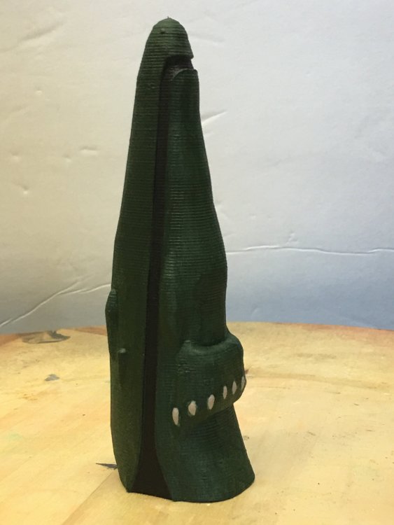
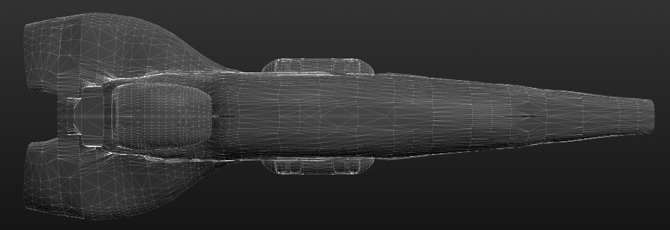
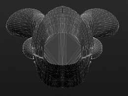
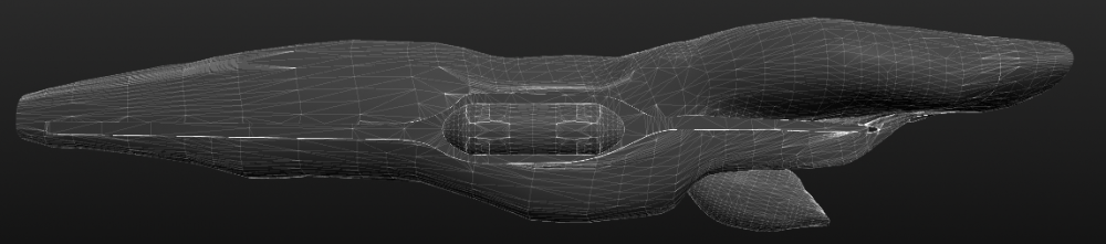
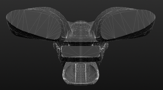
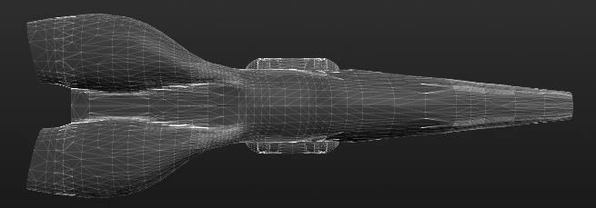
Well it's been a year since I have been working on the Salan Scout. Just before Xmas vacation, I got a 3d printer. I was originally planning on designing and printing the lower engine, engine fins and the rear engines. But then I thought I should push myself out of my comfort zone of 3d modeling and make a fully detailed 3d model of the scout which then can be printed. So over the break, I upgraded to ViaCAD10 Pro from ViaCAD 9 so I can get access to the advance mesh/solid tools. Also, I needed away to digitally sculpt the hull like clay. Before sinking lots of cash into ZBrush, I started using their free version, Sculptris. The pictures below are from Sculptris showing my current progress with the ship. The hull, the side pod and lower engine models are exported from ViaCad and then imported into Sculptris. This is a quick way for me to assemble the ship to get a since of portion and shape. The next step is to add more details to the rear pod launcher and begin the process of hollowing out the top engines and adding the exhaust fins.

-
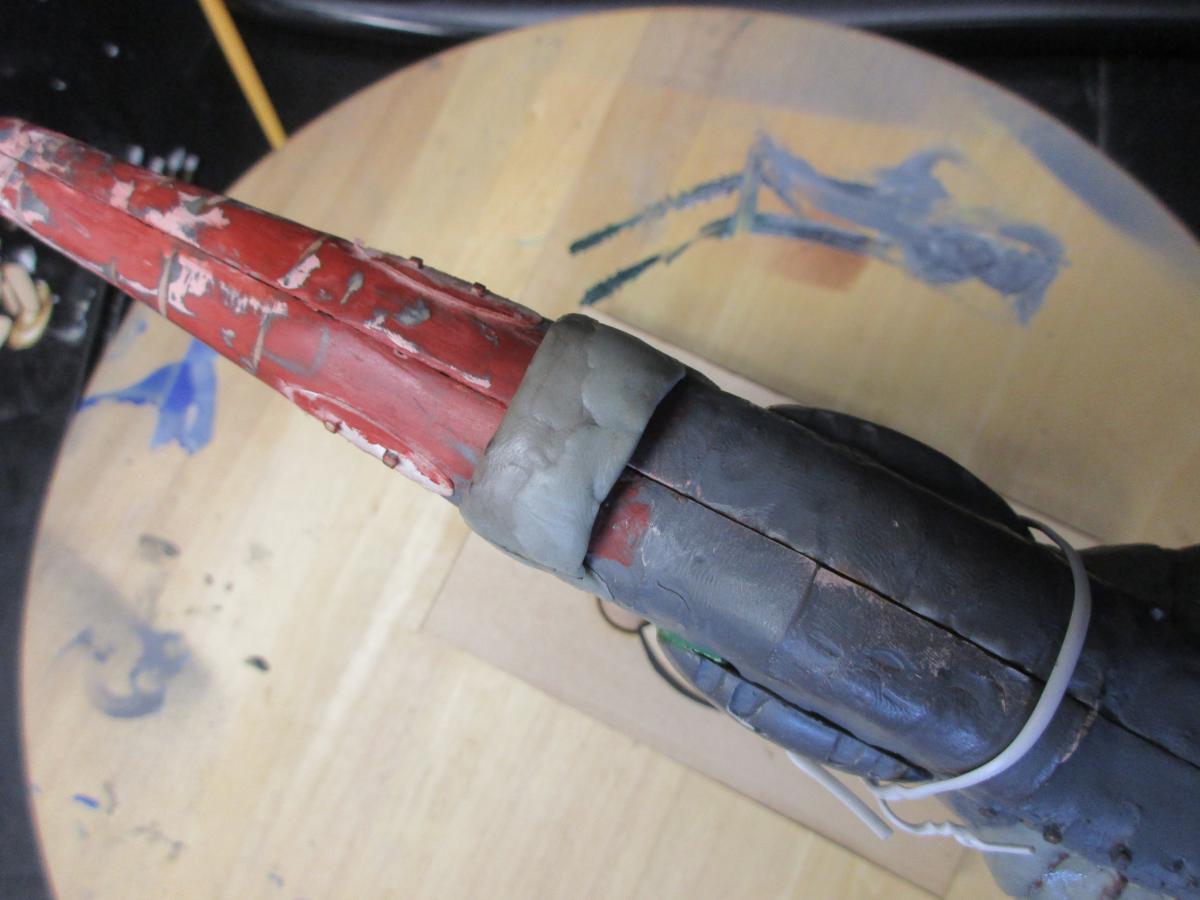
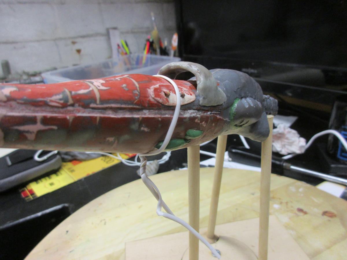
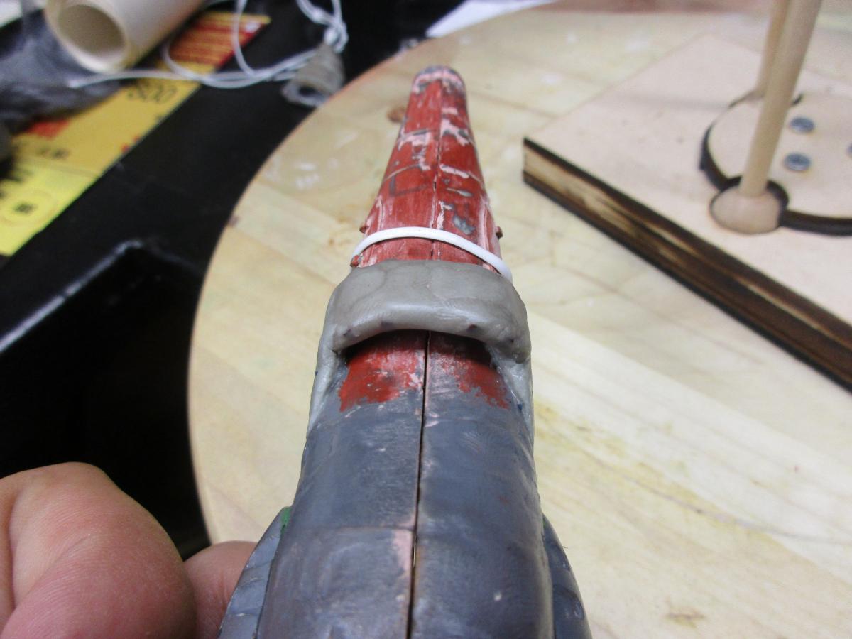
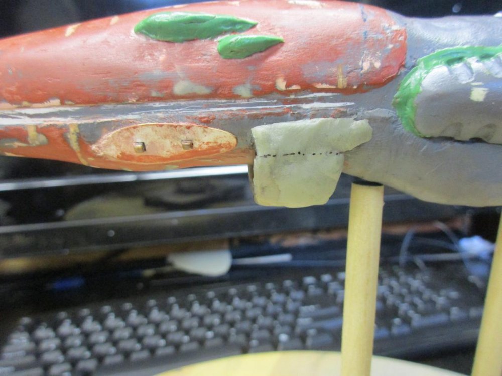
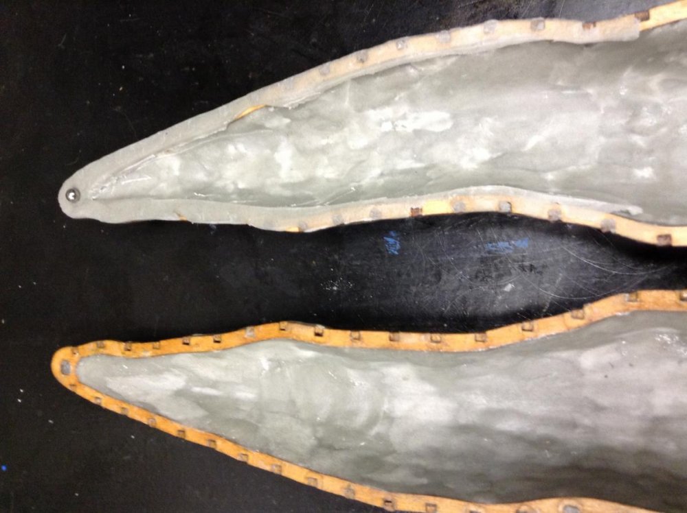
Over the weekend , I have been concentrating on three portions of the scout. The last post covered the effort being made on the rear portion of the engines. The other ones are the continuation of the scoop and filling in the gap between the hull and the engines. The effort in filling in the gap involved drilling and gluing a 3/16" ball bearing to the front of each engine. The engines were lightly glued on to the hull so I don't have to hold them in place while filling the gap. A release agent (Vaseline) was applied liberally on the front of the engines so I can remove them later. Putty was placed into the gap and slightly over the engines. The hulls were opened and the inside gap was filled in and smoothed out. I made the scoop wider to match the scaled width. It still didn't look right. So referring back to pictures and CAD, the portion where the scoop mates with the hull is too high. The black line is about where it should be. So the next effort is to remove portion of the scoop above the line. The alignment pins might need to be removed and new ones created to match the new location.


-
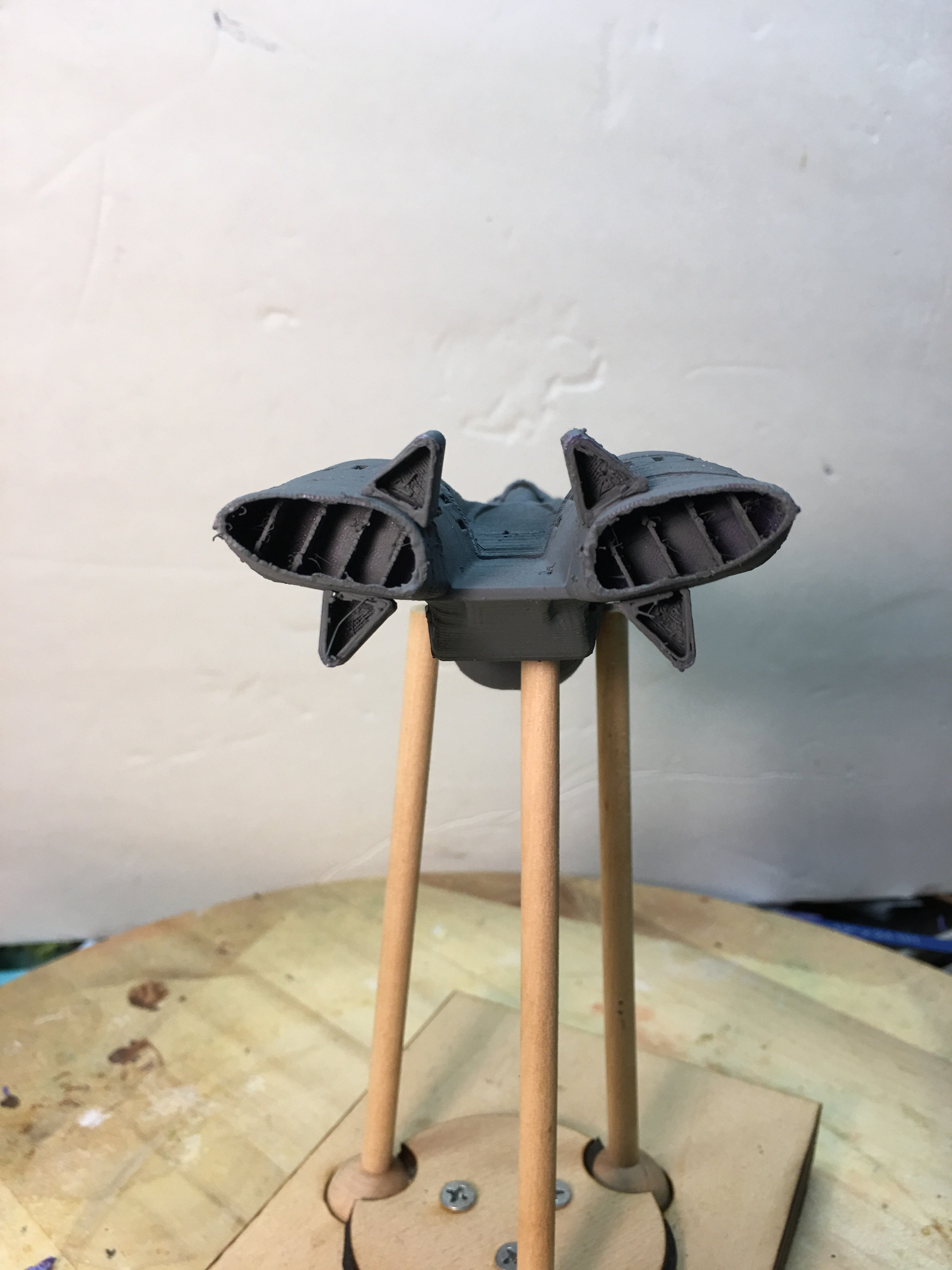
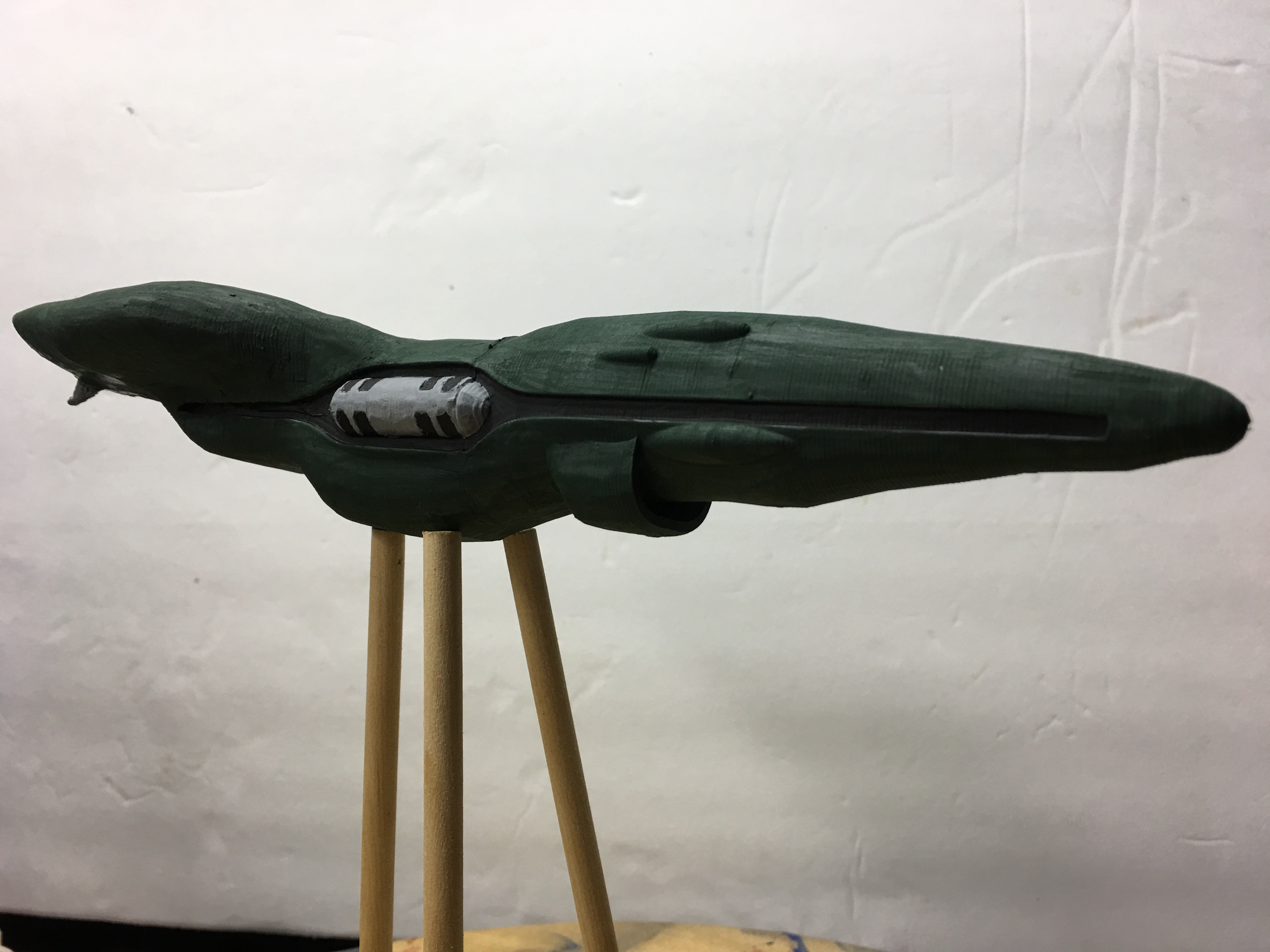
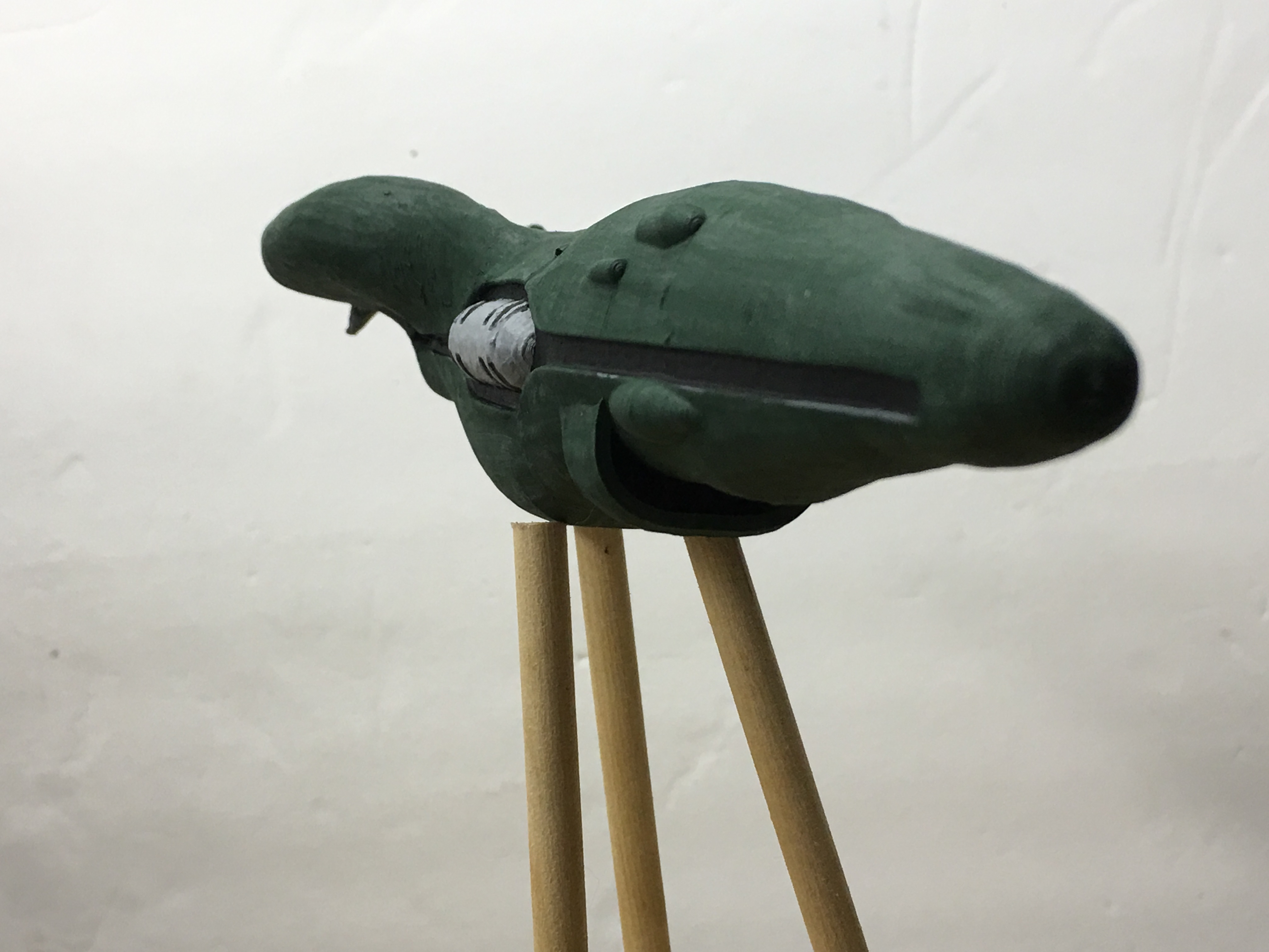
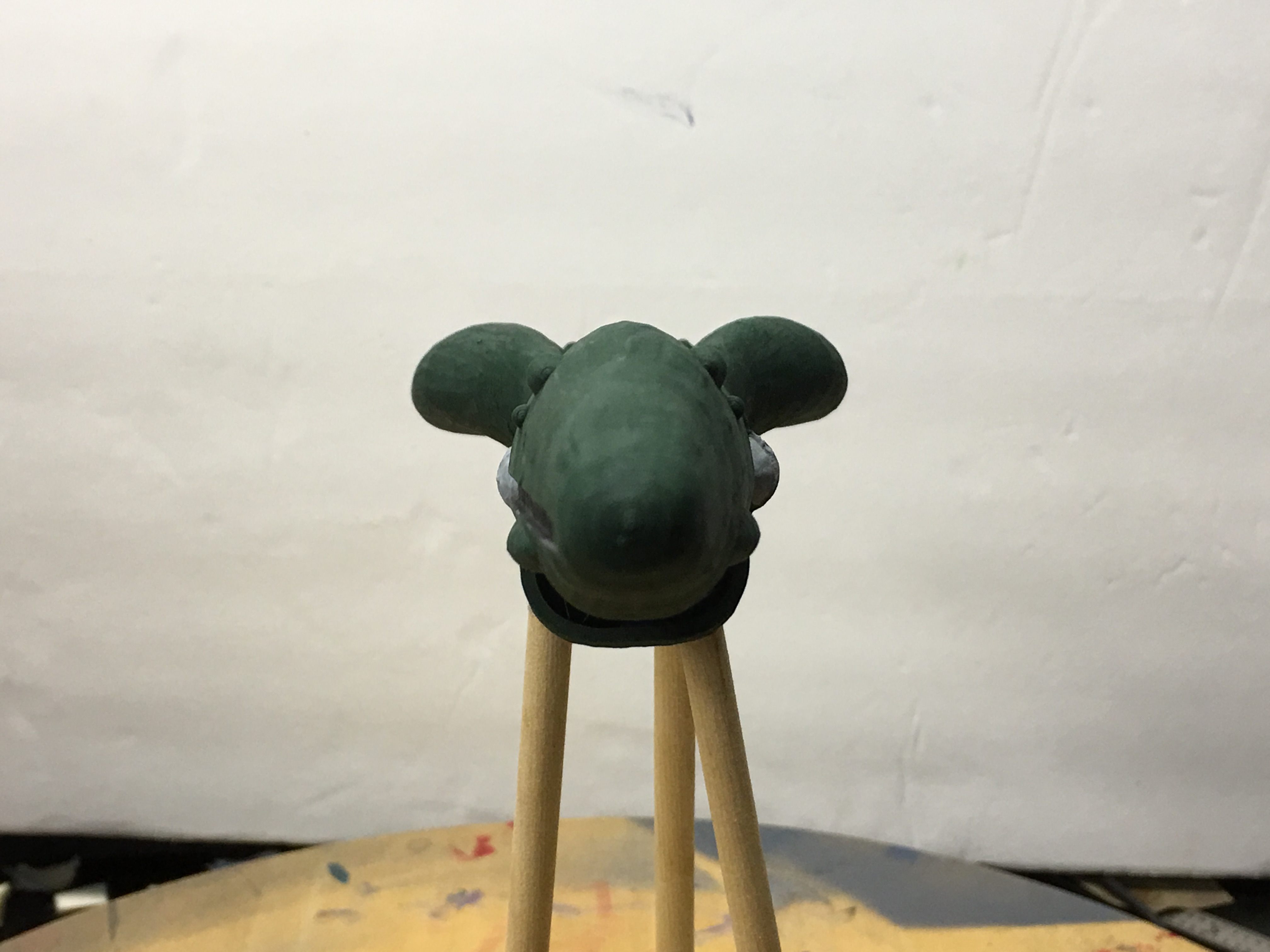
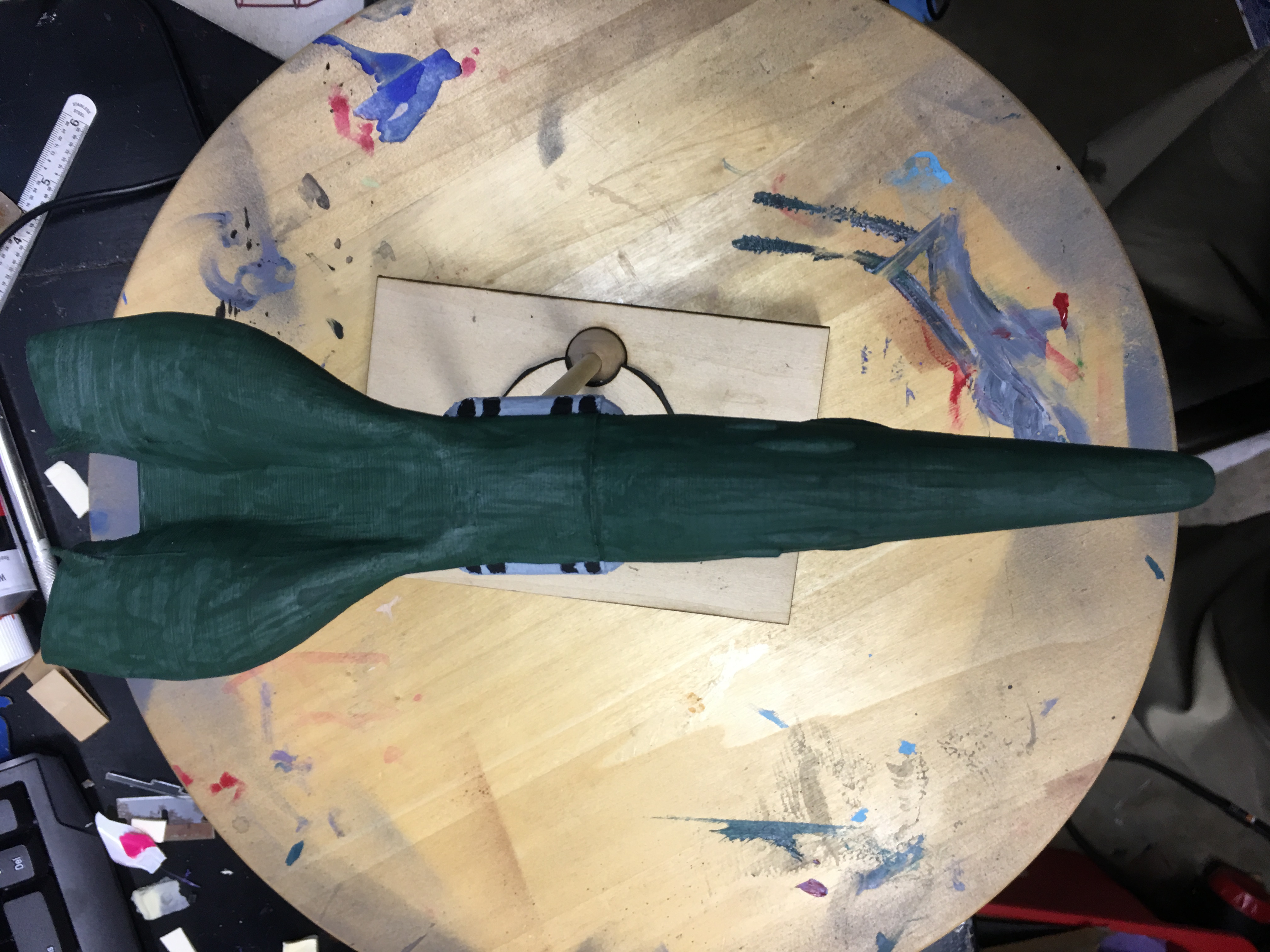
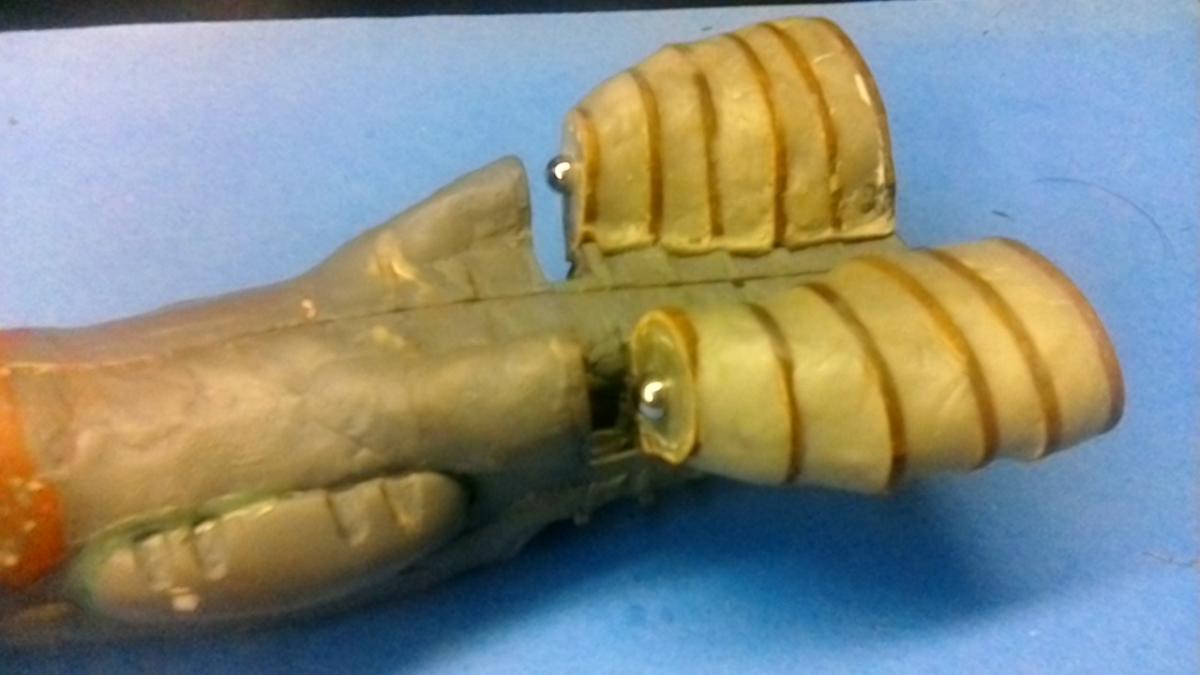
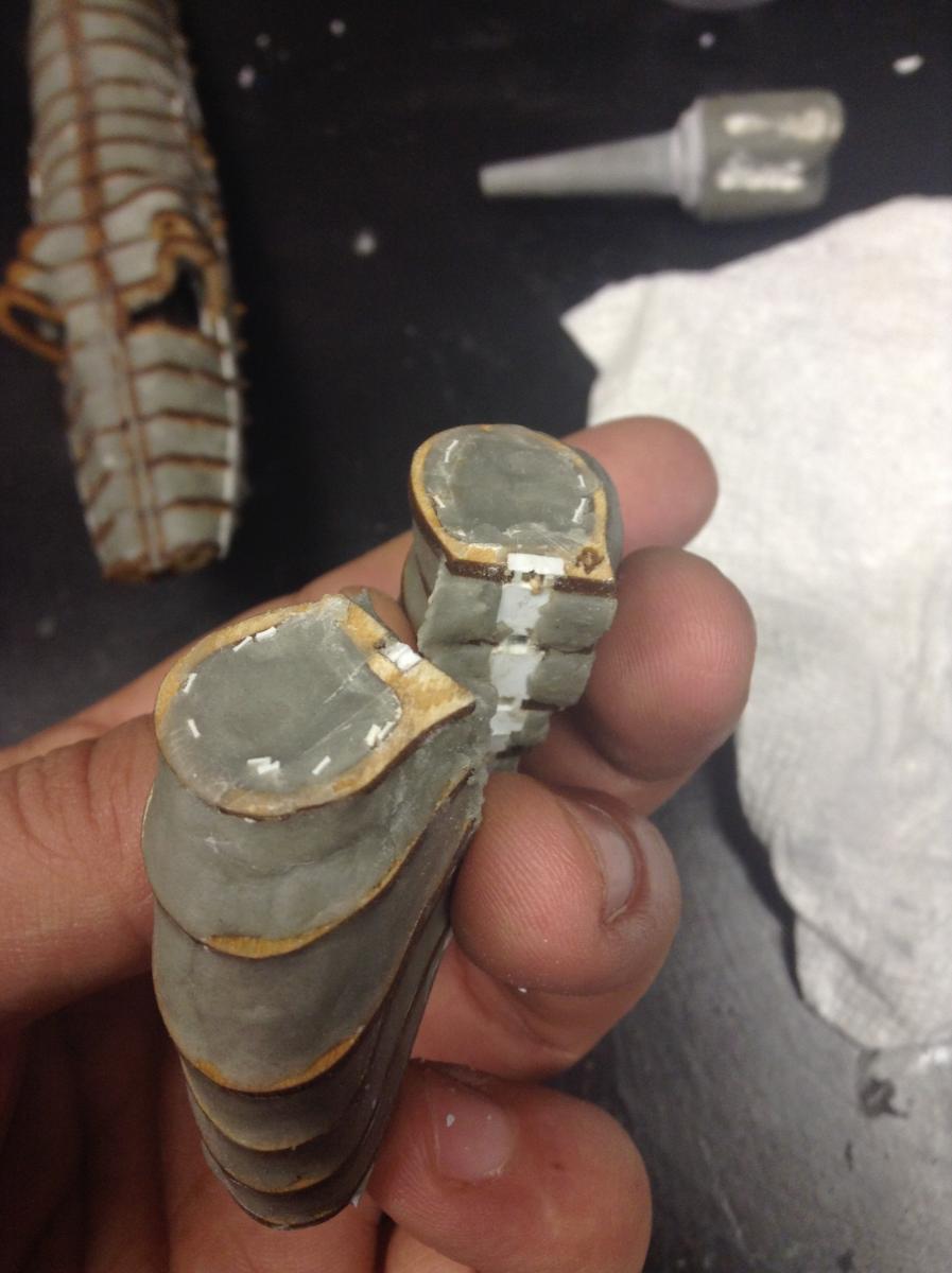
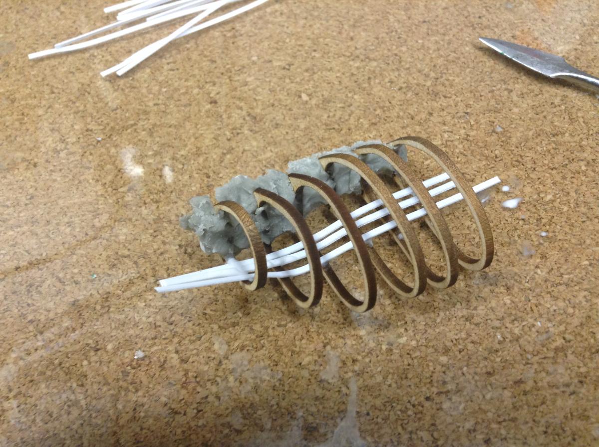
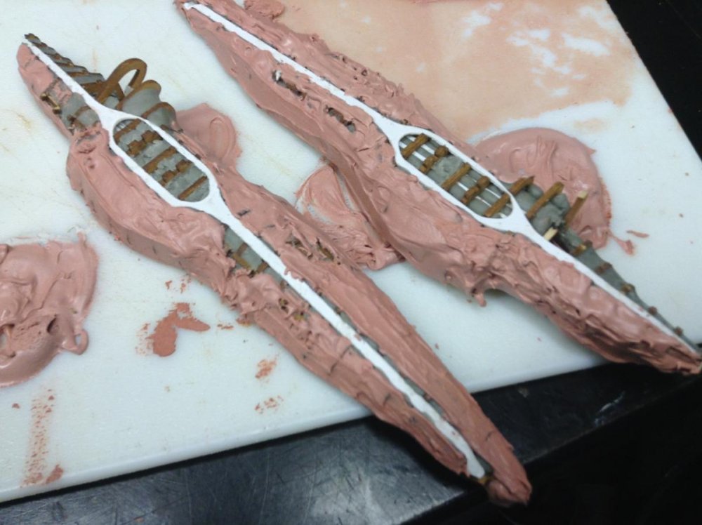
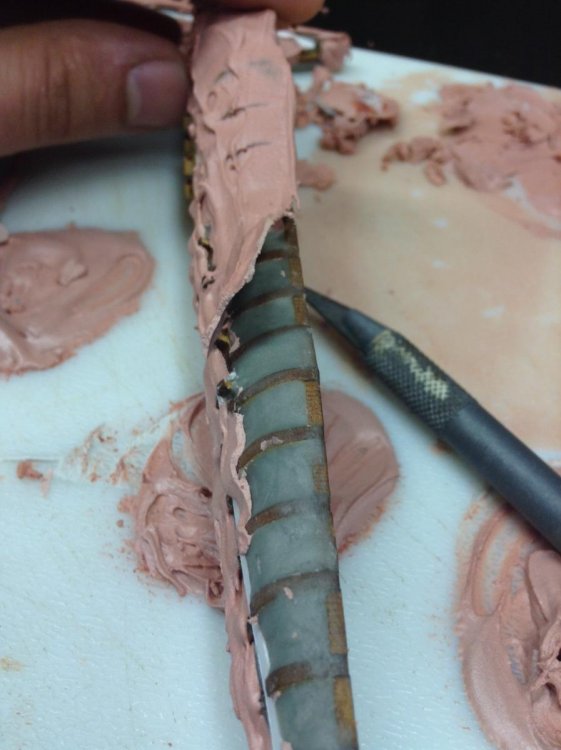
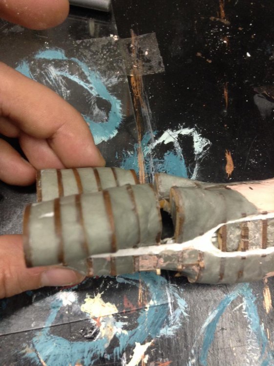
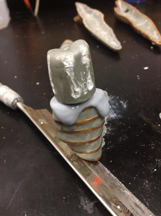
The rear portion of the engines have been challenging for me as I just couldn't think of a meaningful way of making them symmetric and hollow until now. This update covers the approach. The first step was to make both engines nacelles joined as a single piece. This was done for the remaining of engine profiles except for the last one due to the step angle. All the profiles were notched were they will separate from each other. Cutting were the notch is will make the process of separate the engine halves a lot easier. The step was to create a jig to hold the profiles in place so I can glue them to the center spare. Once the glue cured, I applied a thin layer of putty to the top halves making sure I didn't cover the notches. I am still waiting for the first layer of putty to cure. I might add another layer of putty before I detach the top portions of the engines. I will post as I work on this, So far, it is working as planned.


-
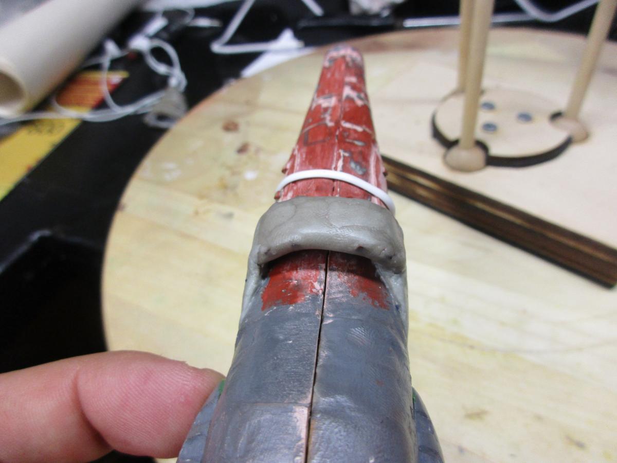
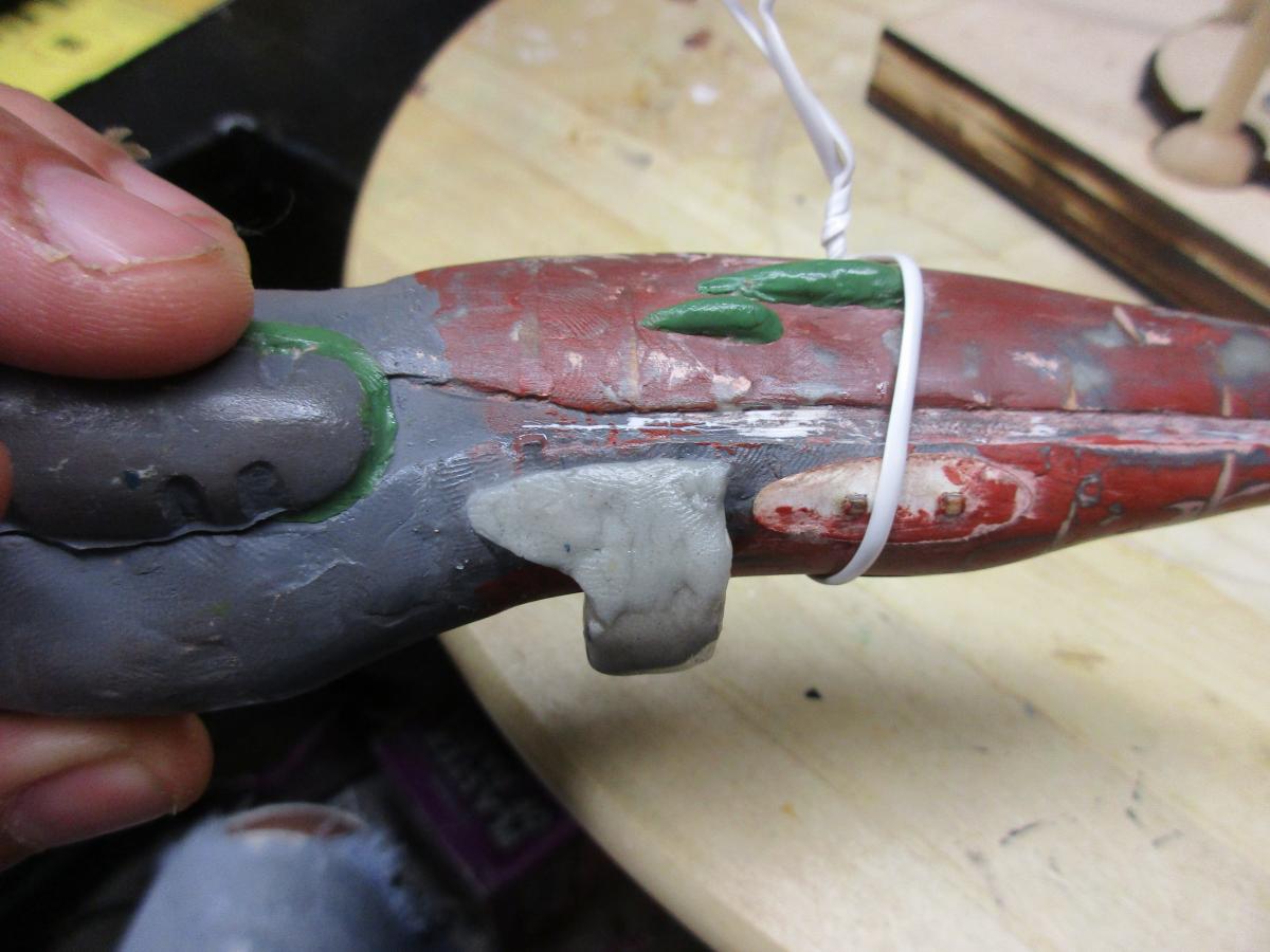
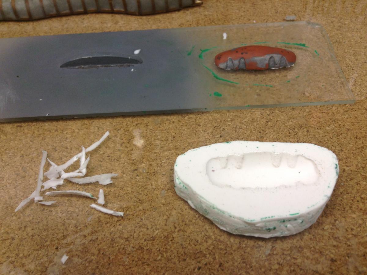
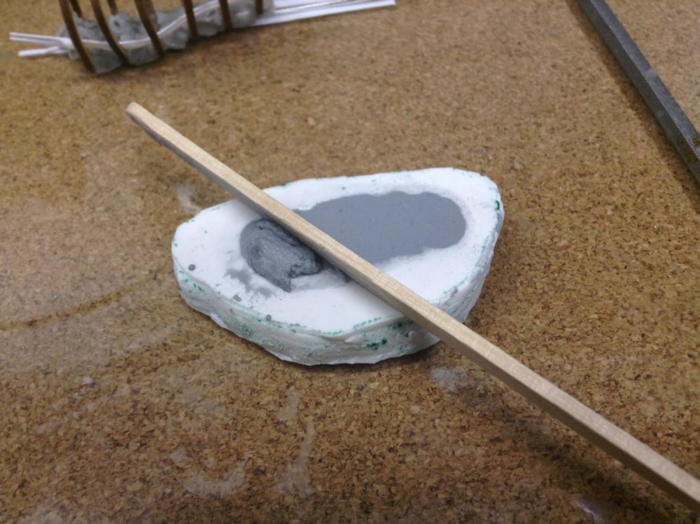
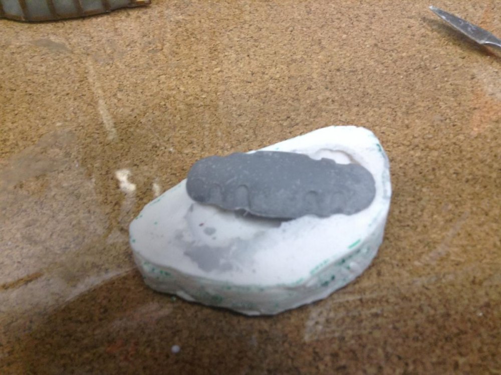
This update covers the effort made on the lower scoop. I went ahead and used the frame I made earlier and shaped it with Apoxie Sculpt just above the portion that will mate with the hull. Once this cured, I applied a release agent to the hull (Vaseline) where the scoop will meet the hull. I applied a small amount of putty to each end of the scoop and pressed it against the hull. The putty will capture the alignment pins, as well as the hull shape. Once this cures, I will separate it from the hull and continue sculpting and shaping. The next part is to create the little scoop pod and then make mold of it. I think I will need to make about 8 of them for the scoop. Also, once I feel I have the scoop at the right portion, I will concentrate on the lower hull pods just in front of the scoop. I would like to thank everybody for the encouragement. This project has been quite the adventure in pushing my modeling skills beyond what I have done before. Hopefully by sharing my experience, I can empower someone to make something! TP


-
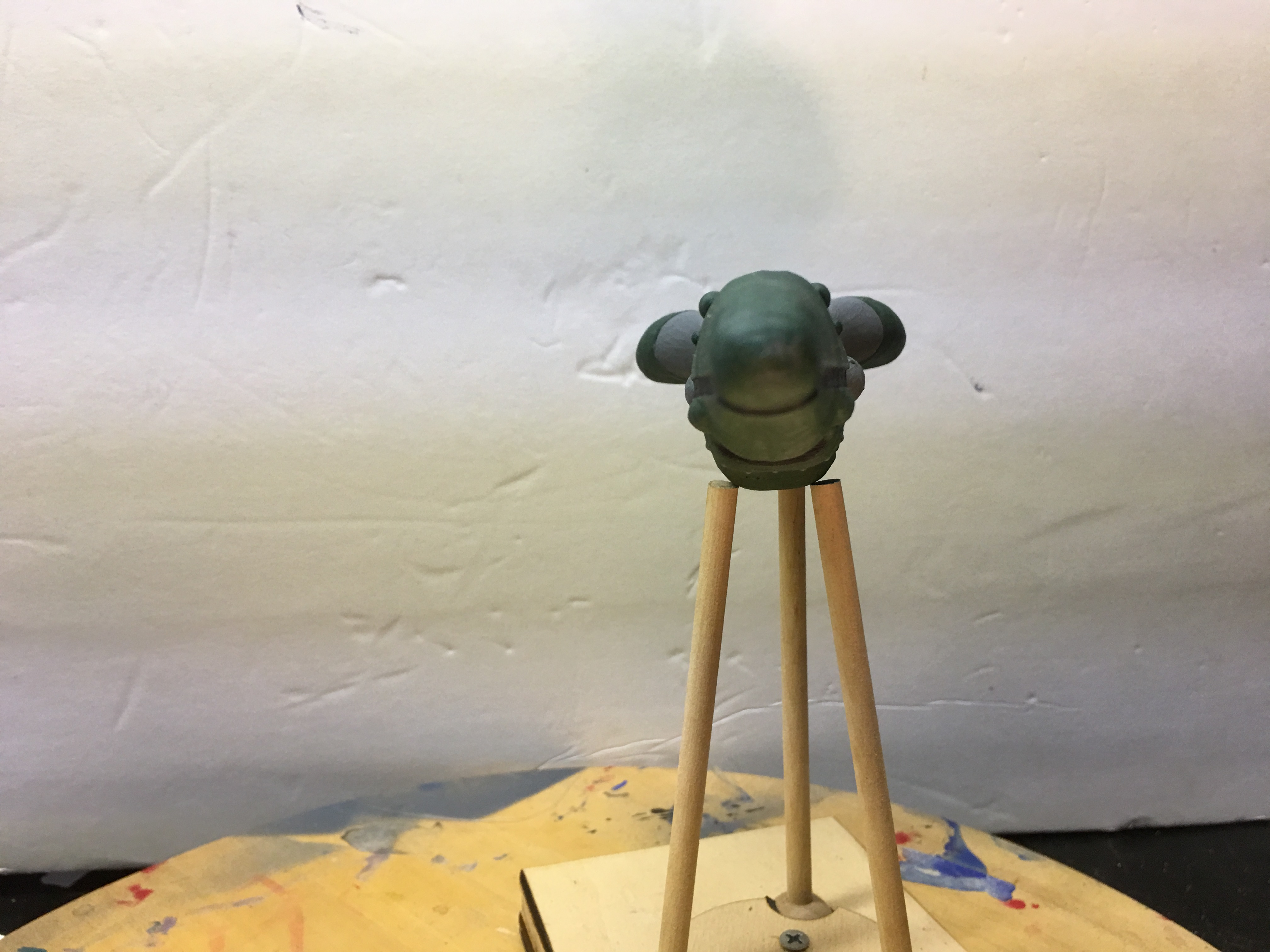
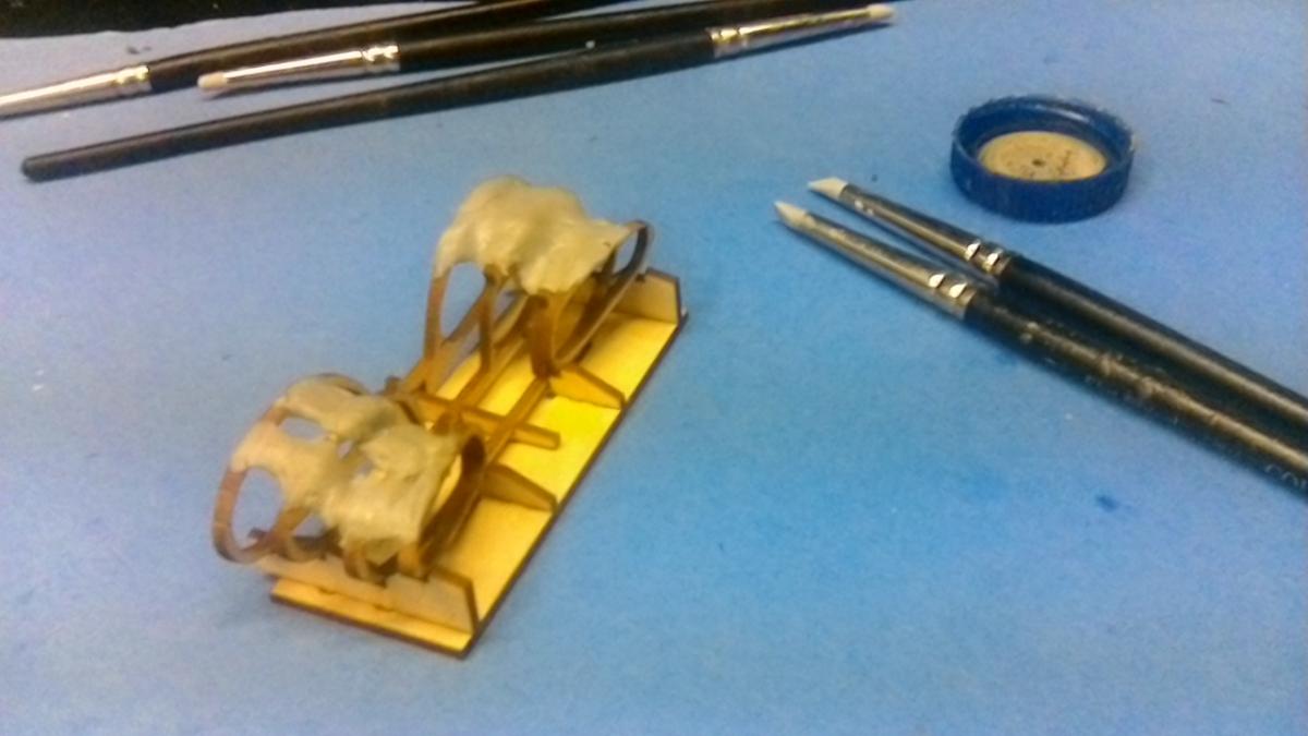
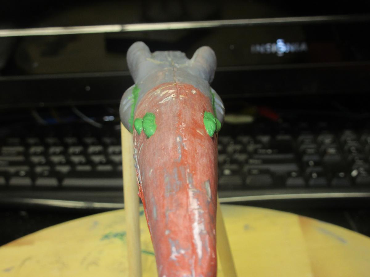
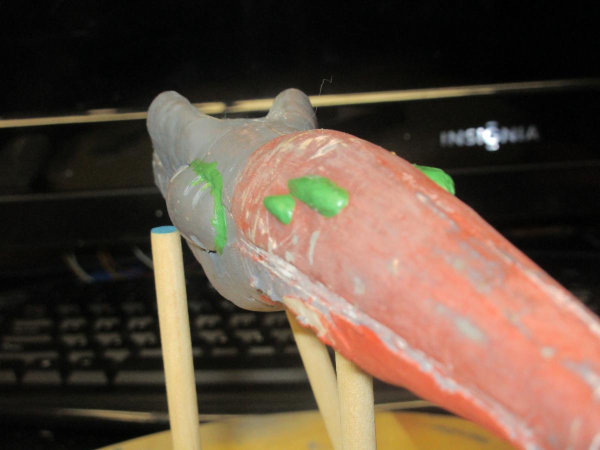
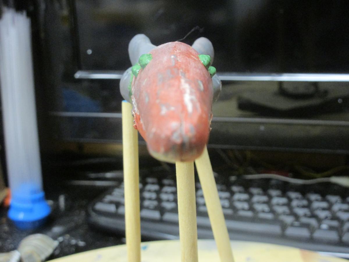
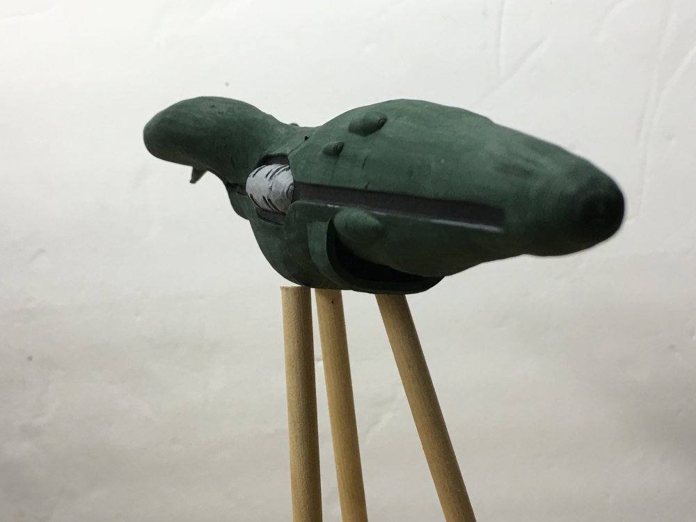
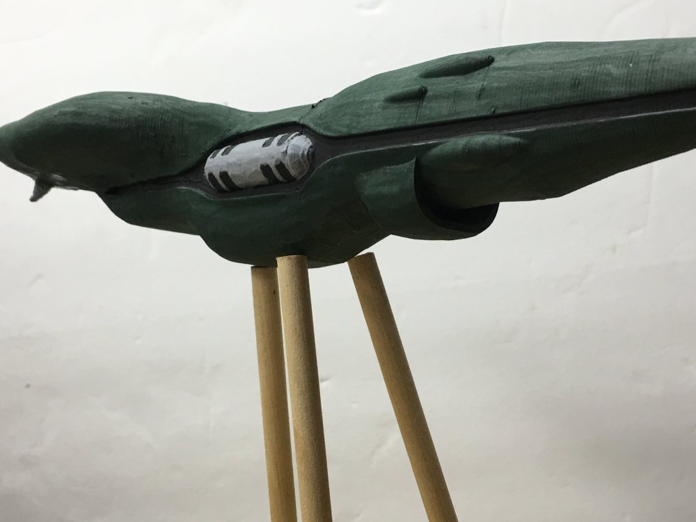
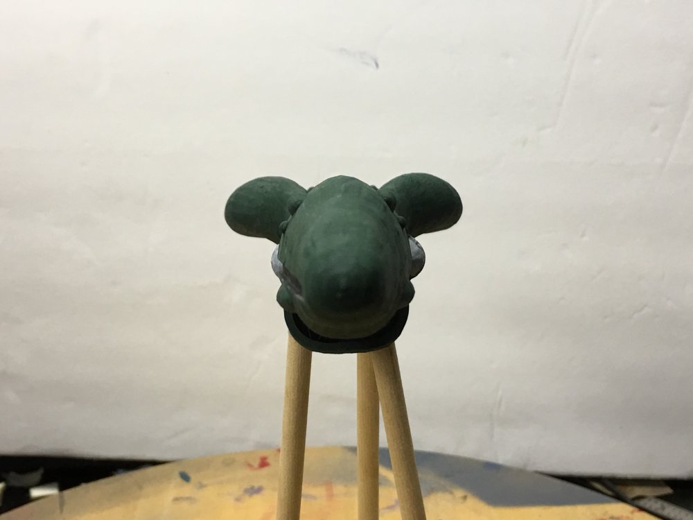
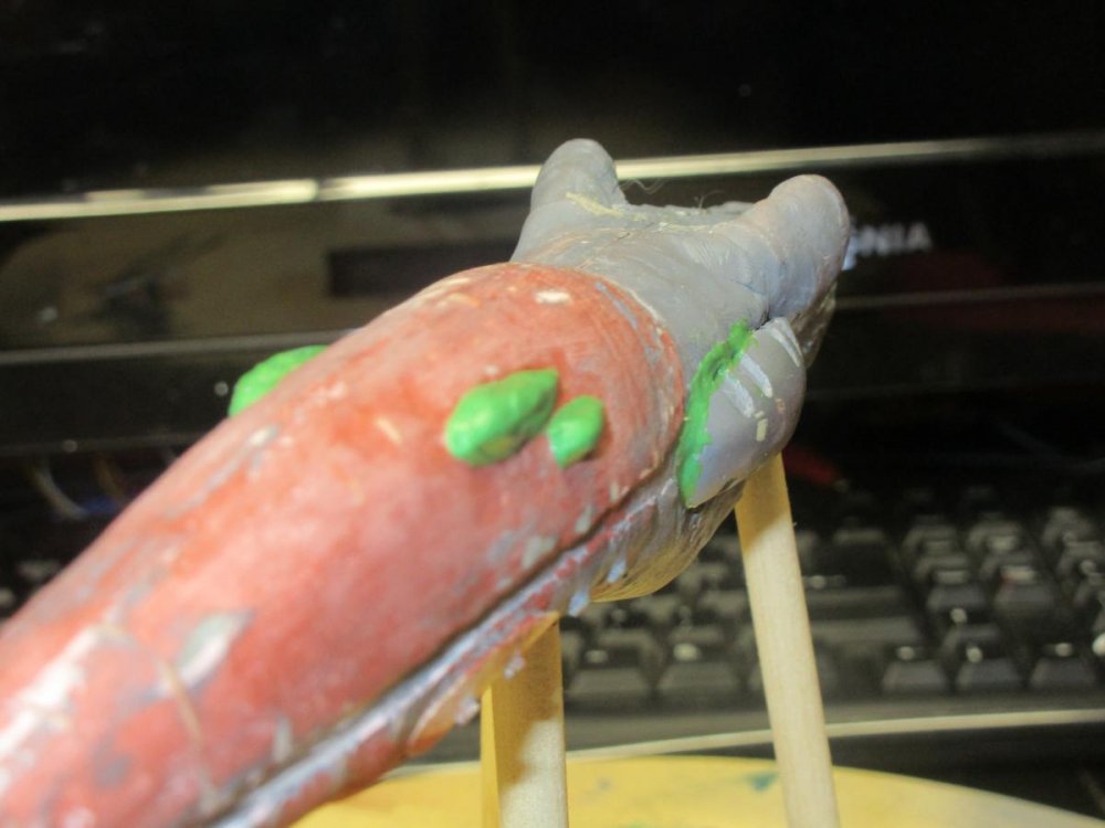
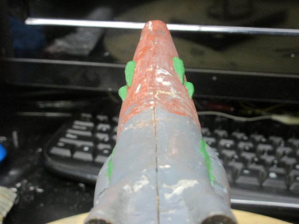
It's been awhile since my last post! I had other projects that needed to get finished before I could get back to the Scout. I figured the best starting point was to sculpt the front top pods. I used green stuff as the medium. The sculpting tools used were the silicone tip brushes from Colour Shaper. I won't know how well I did on proportion until I can hit them with some primer. The extra putty was used to start filling in the gaps around the side pods . The top pods will help me re-position the bottom pods in relation with the scoop. I'm thinking I might need to make the scoop a tad bit wider to make it fit the hull better.


-
I managed to have some time to build a rough draft of the scoop. I wanted to see if I was in the ball park in profile and size before continued on with the scoop. It looks about right. It will be a day or two before I can get back to the model so lets see how I feel about it then. I might have to file down the alignment pins a bit to maintain the scoop profile and the bottom pod will need to be redone.

-
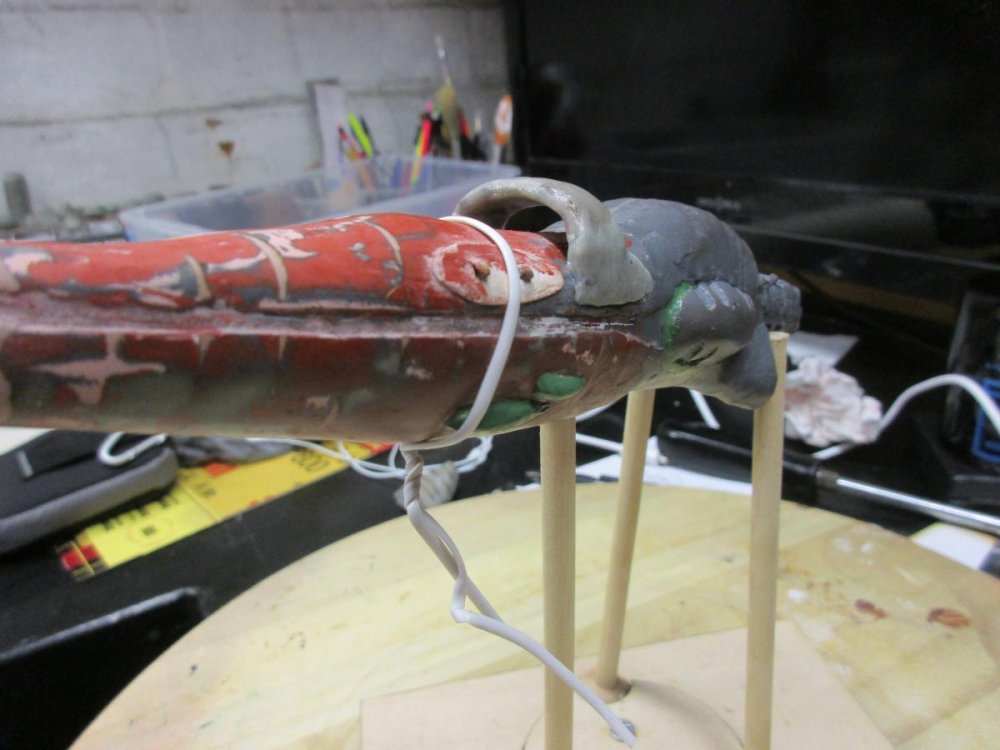
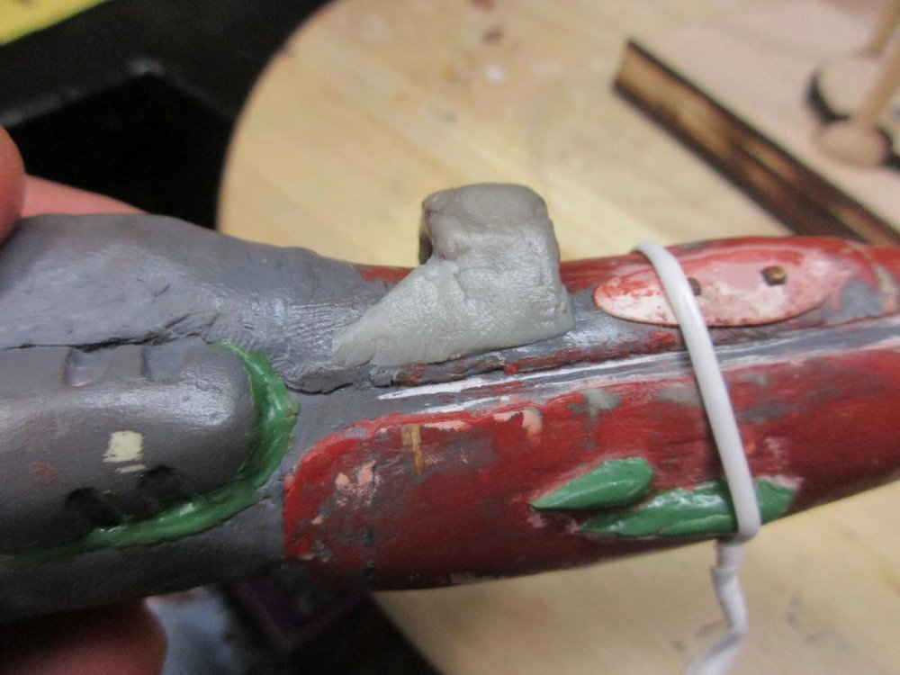
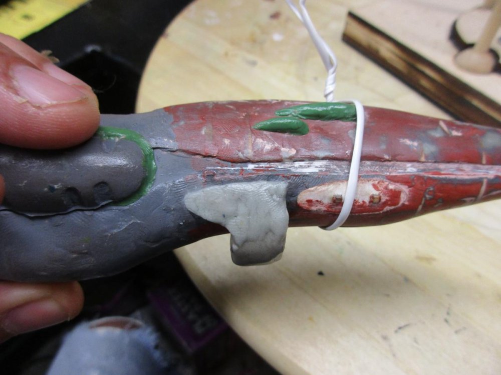
This update shows the start of adding the front pods. The small alignment pins for the smaller front pods were lost during the putty application and sanding. The upper pod alignment pins were still intact so I joined the lower pod base with the upper pod base with a small tab. The tab will be removed once the glue sets. The next stage is to get the lower scoop designed, lazed, assembled and filled-in before the pods are sculpted just in case I might need to re-adjust the pod outlines. The plan for the big gap between the engines and the hull is to fill it in and a hole will be drilled in the casting to allow the wires to get to the engines.

-
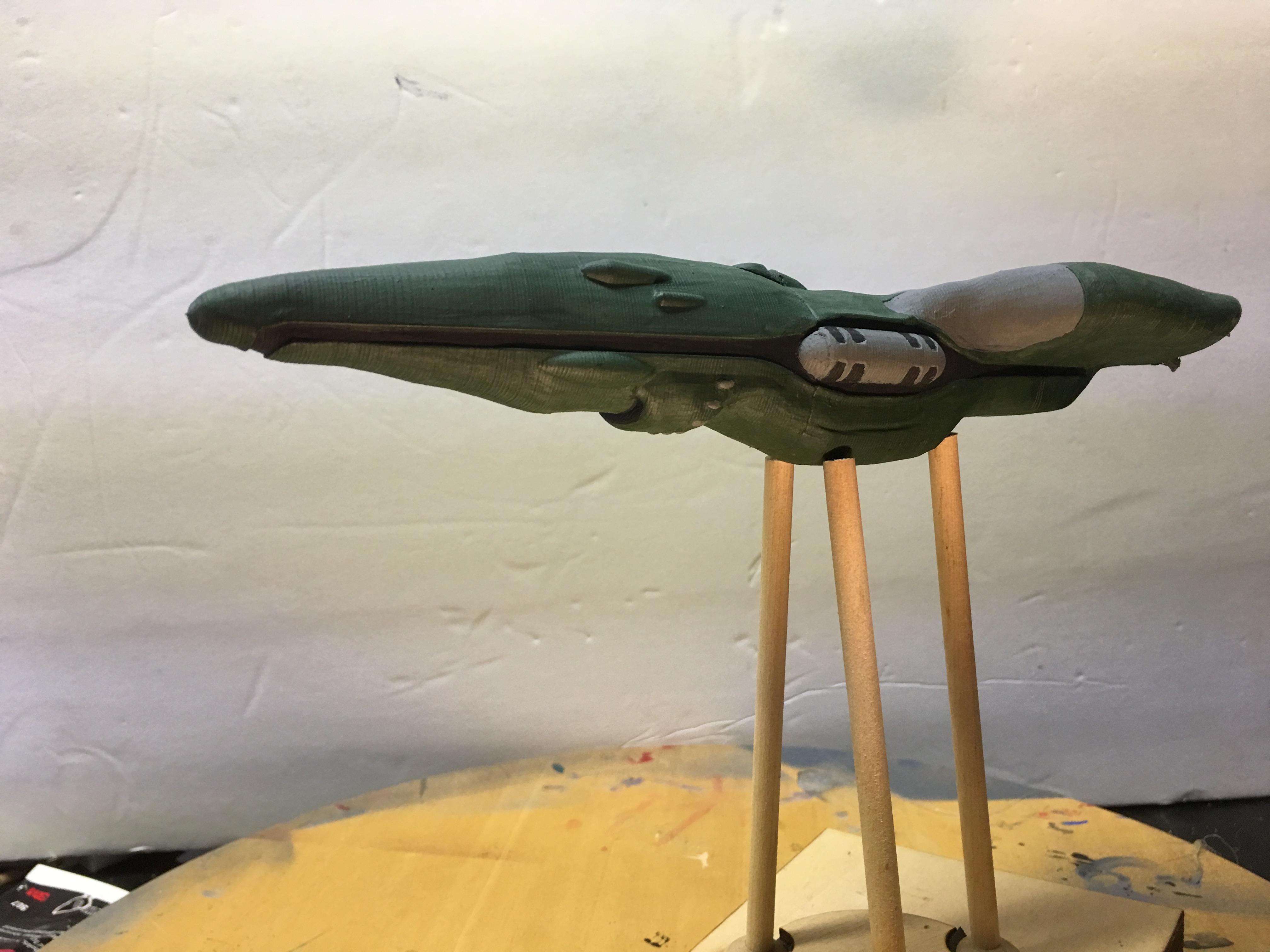
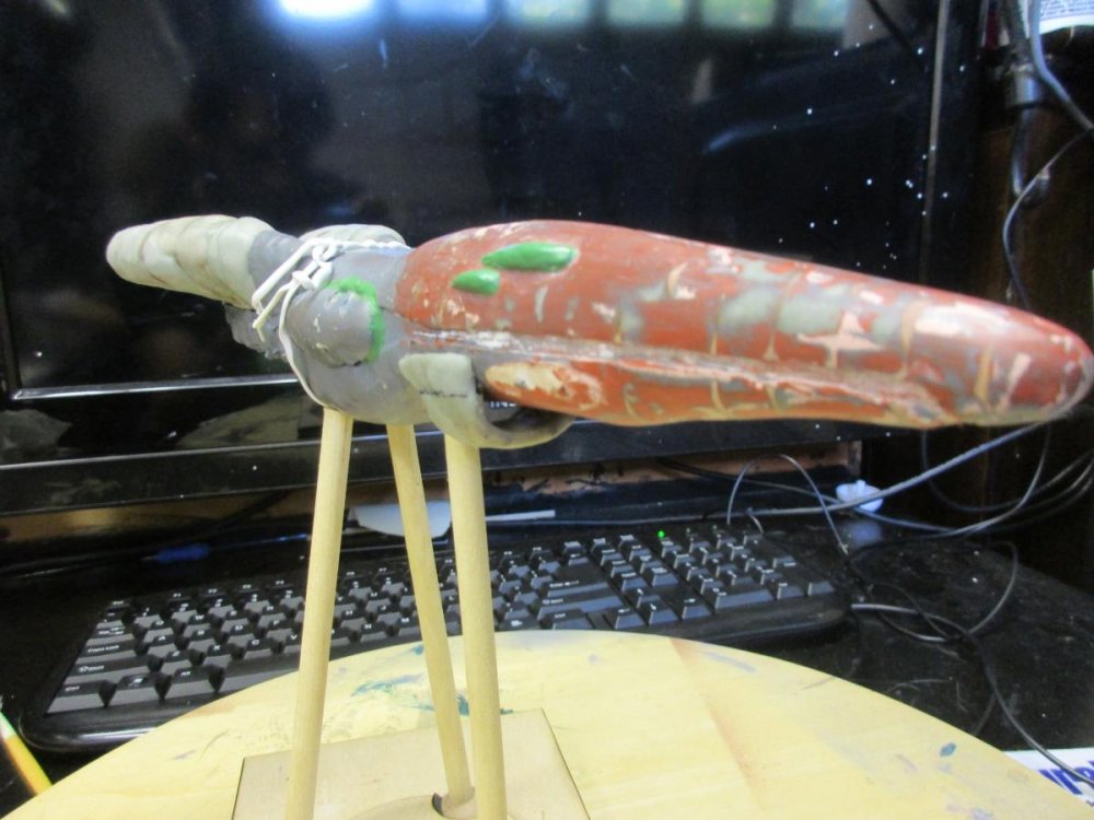
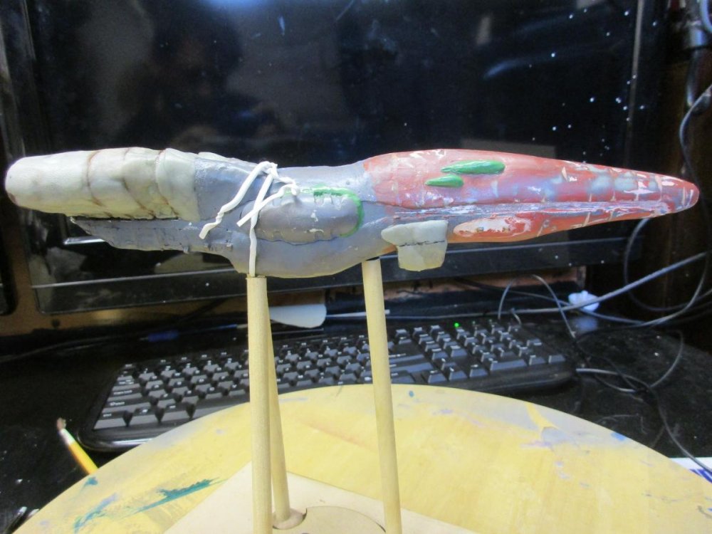
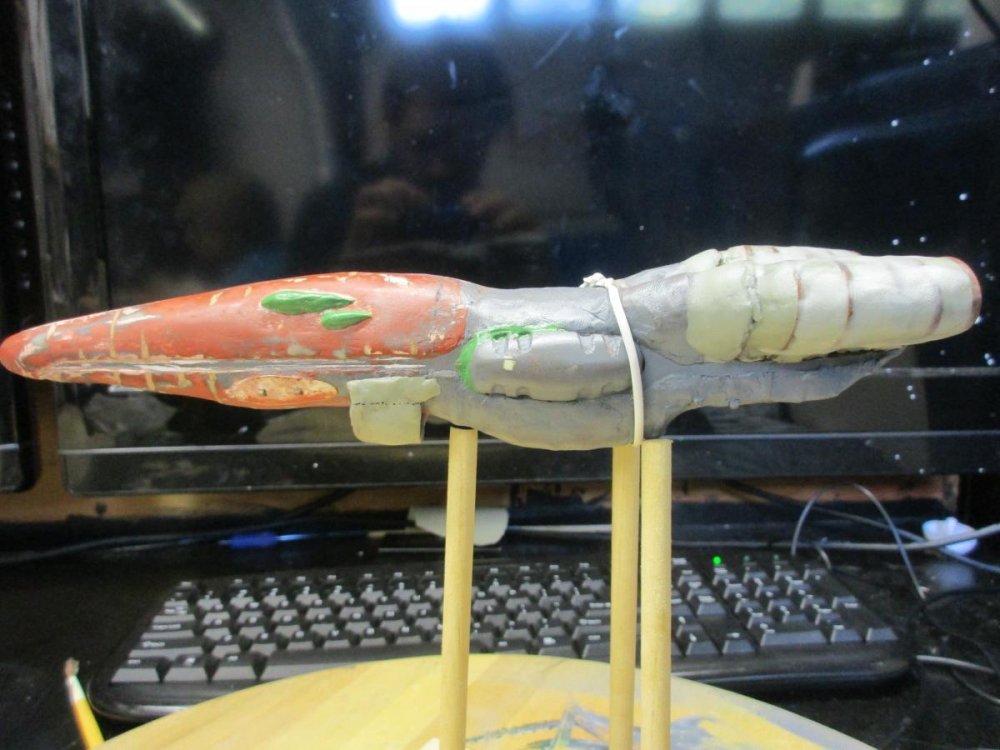
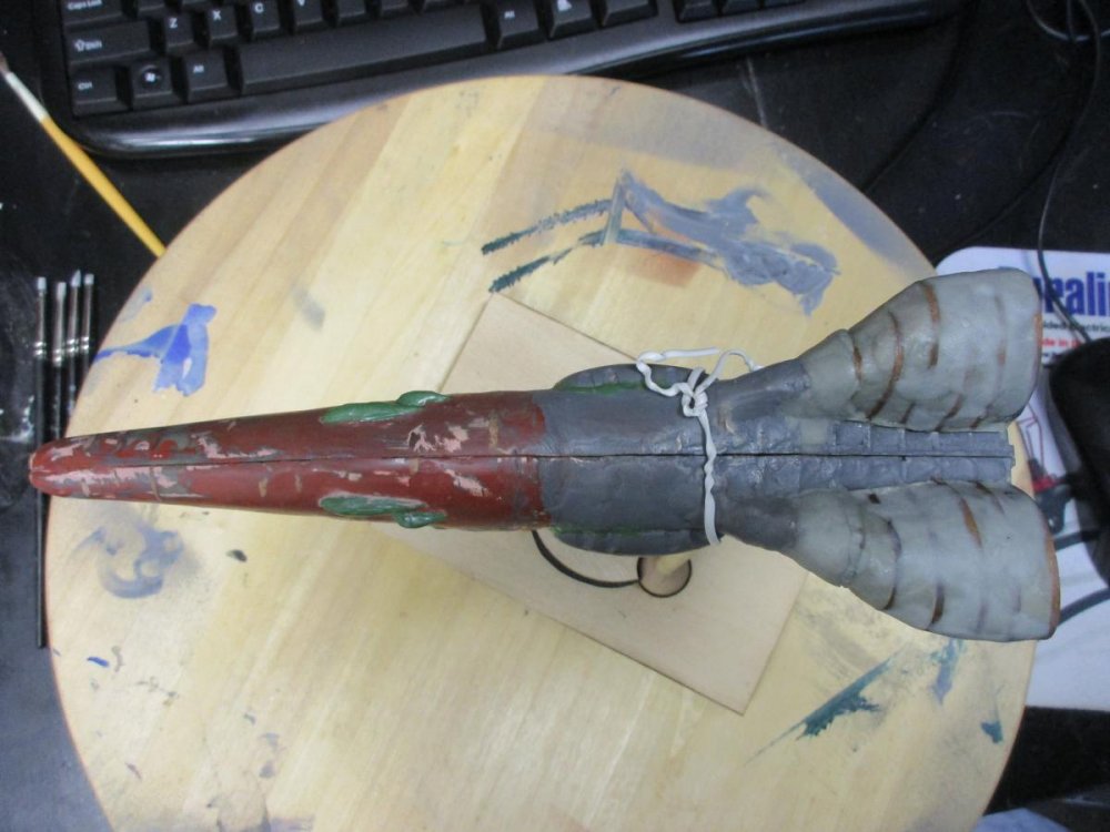
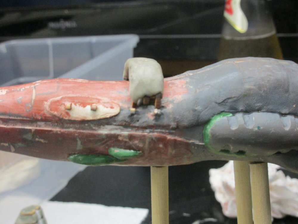
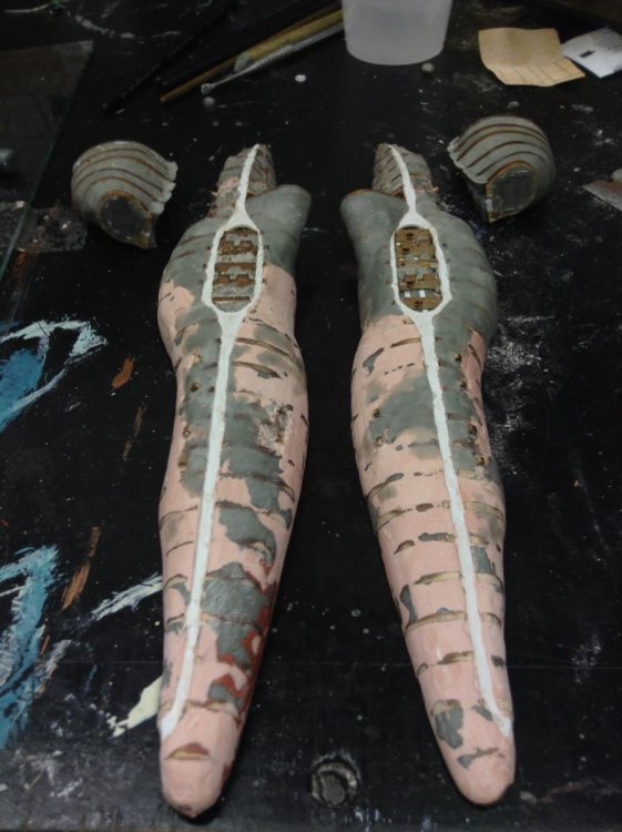
This update covers the shaping of the hull and top engines. I started with Bondo and it peeled easily off the hull. It was either I didn't clean the surface well enough or it does not adhere to Apoxie Sculpt. I tried two different glazing putties and both adhere to Apoxie Sculpt. I continued on with the two part glazing putty. Two issues with this putty: 1) It would, at times, break off. 2) I placed the putty on to thick and I just end up with a lot of work sanding the excess to get to the shape. I was concerned with the breakage so I tried Apoxie Sculpt and found I could strategically apply and work the putty to shape. So I switched over to Apoxie Sculpt to finish up the shaping of the hull and engines. The first set of pictures show the applied and peeling Bondo. The next picture shows some progress with the glazing putty and the remaining pictures show the progress I made with Apoxie Sculpt. More sculpting, primer, sculpt and/or apply glazing putty until the shape is just right. I still need to fill in the huge gap between the hull and engines. The next update will cover my progress with shaping.


-
Cool! Keep up the work. I will be watching your progress on this one especially on how you tackle the clear parts.
-
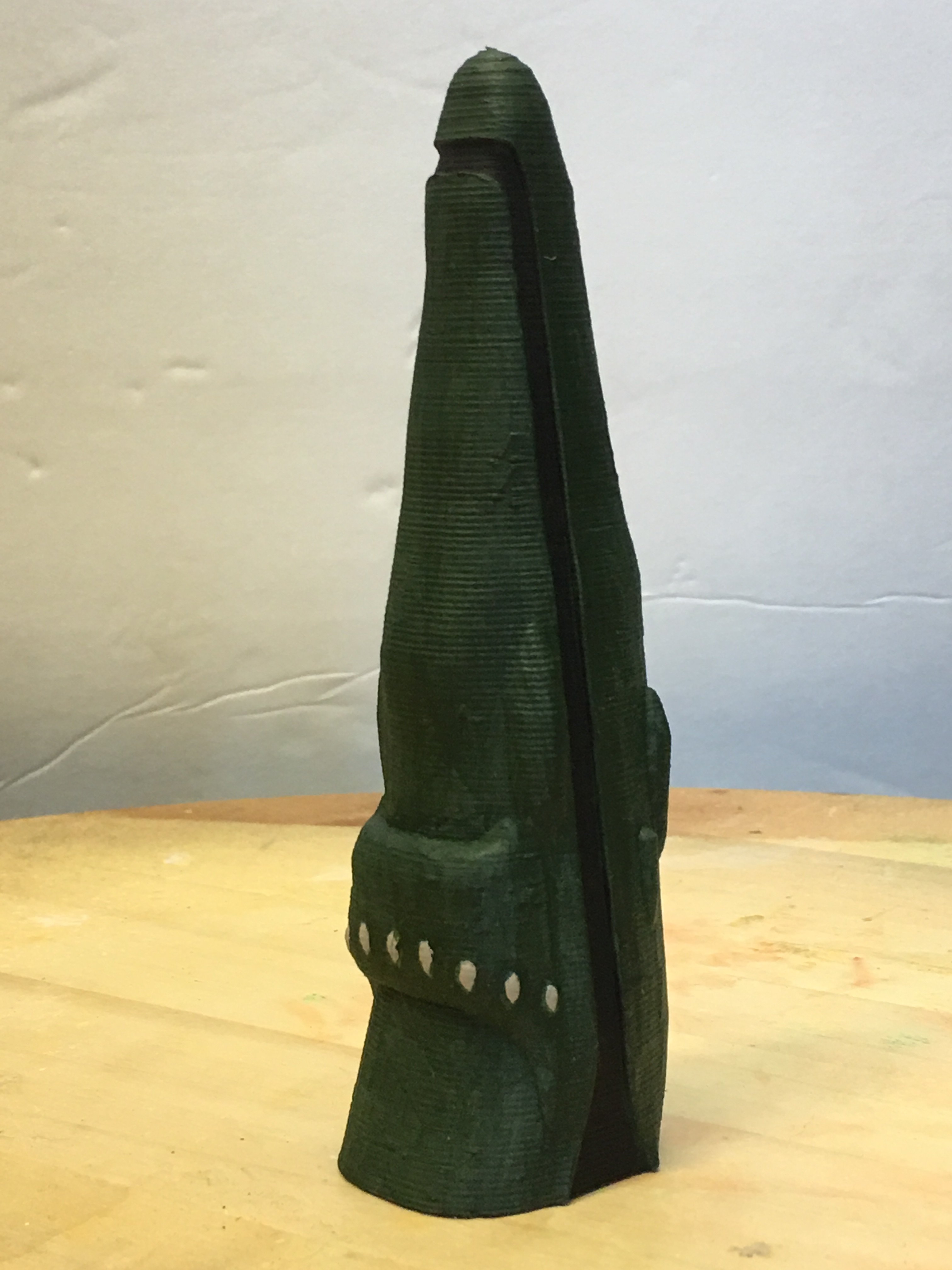
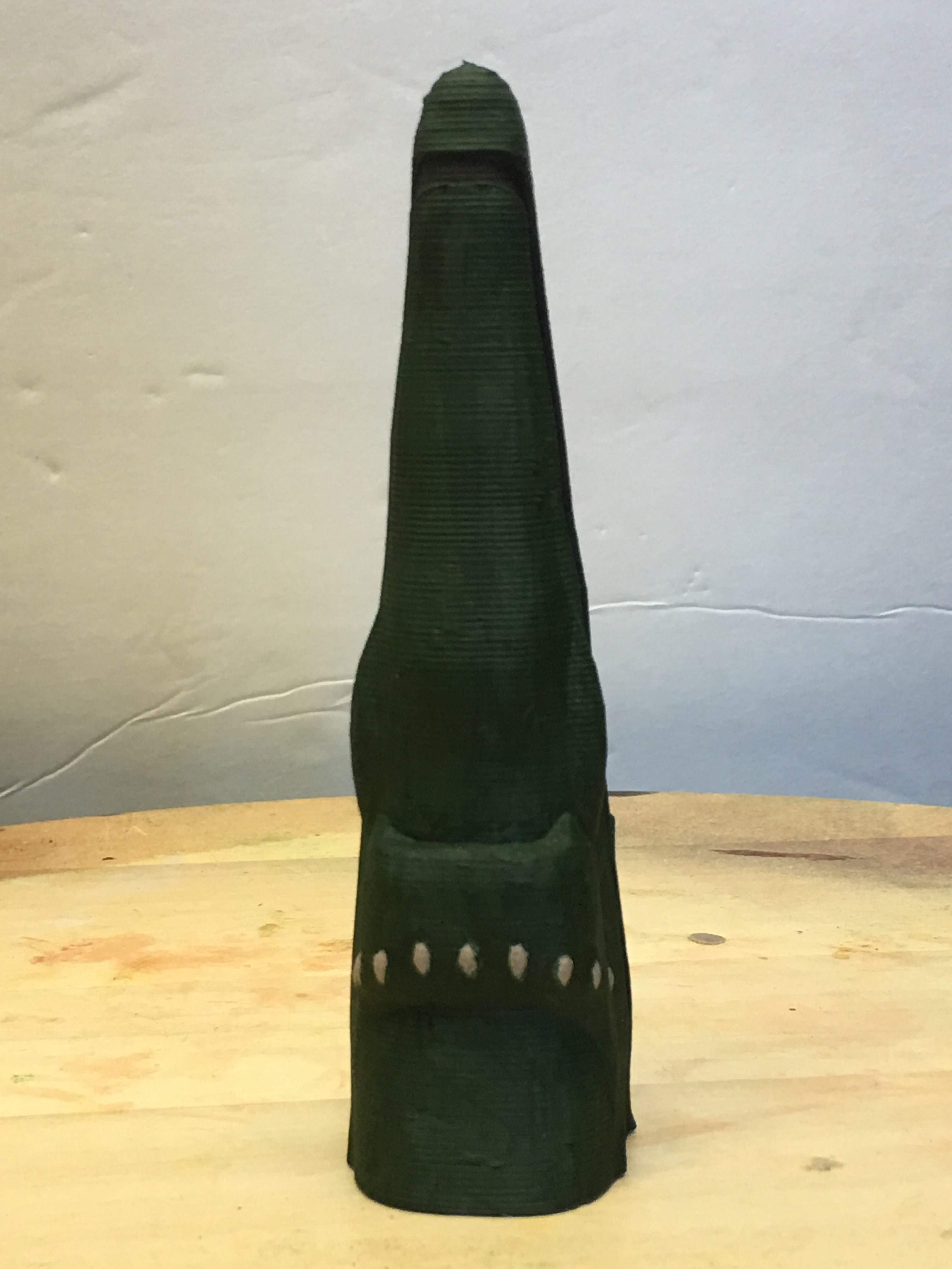
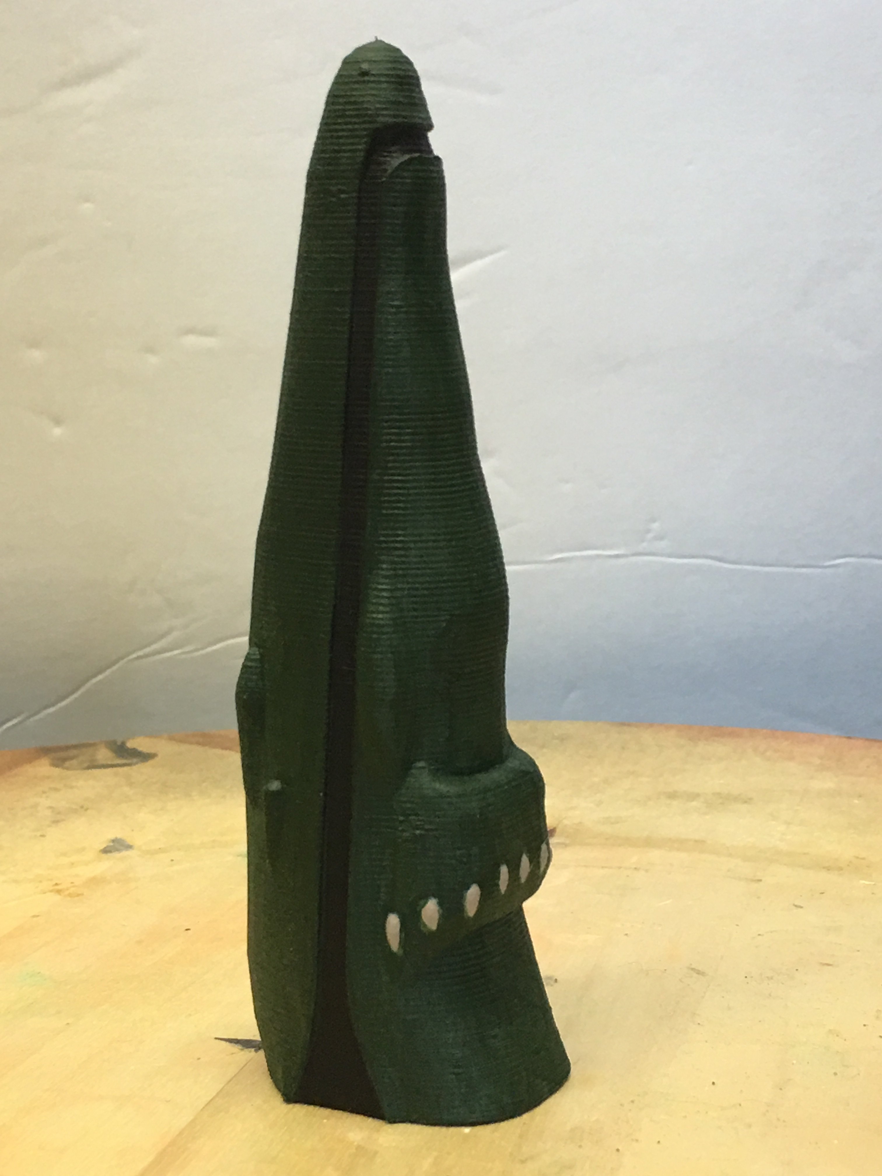
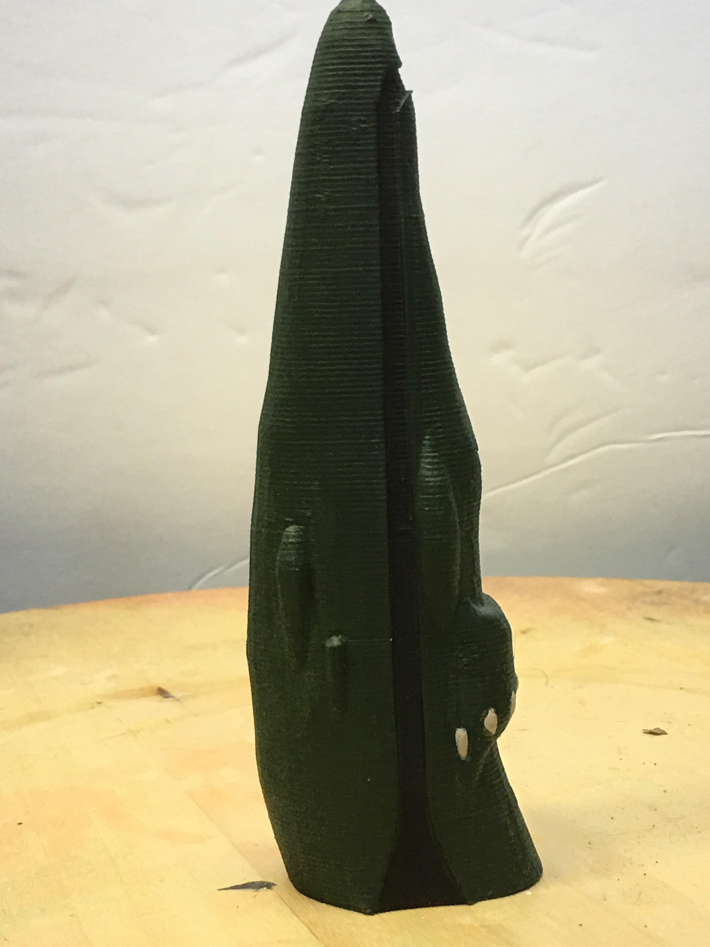
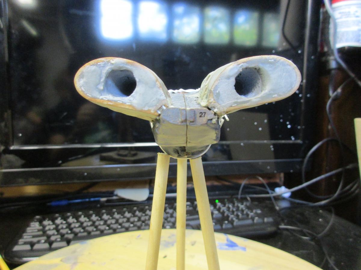
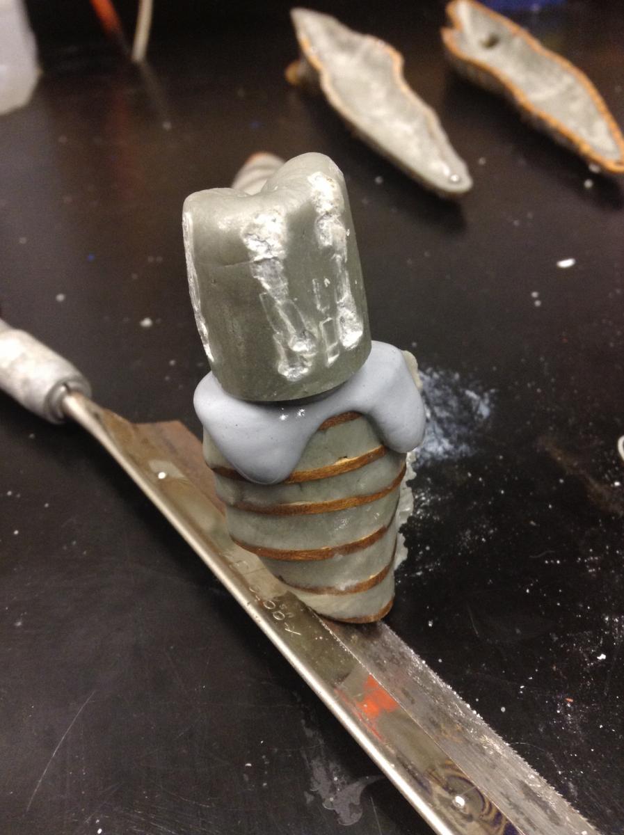
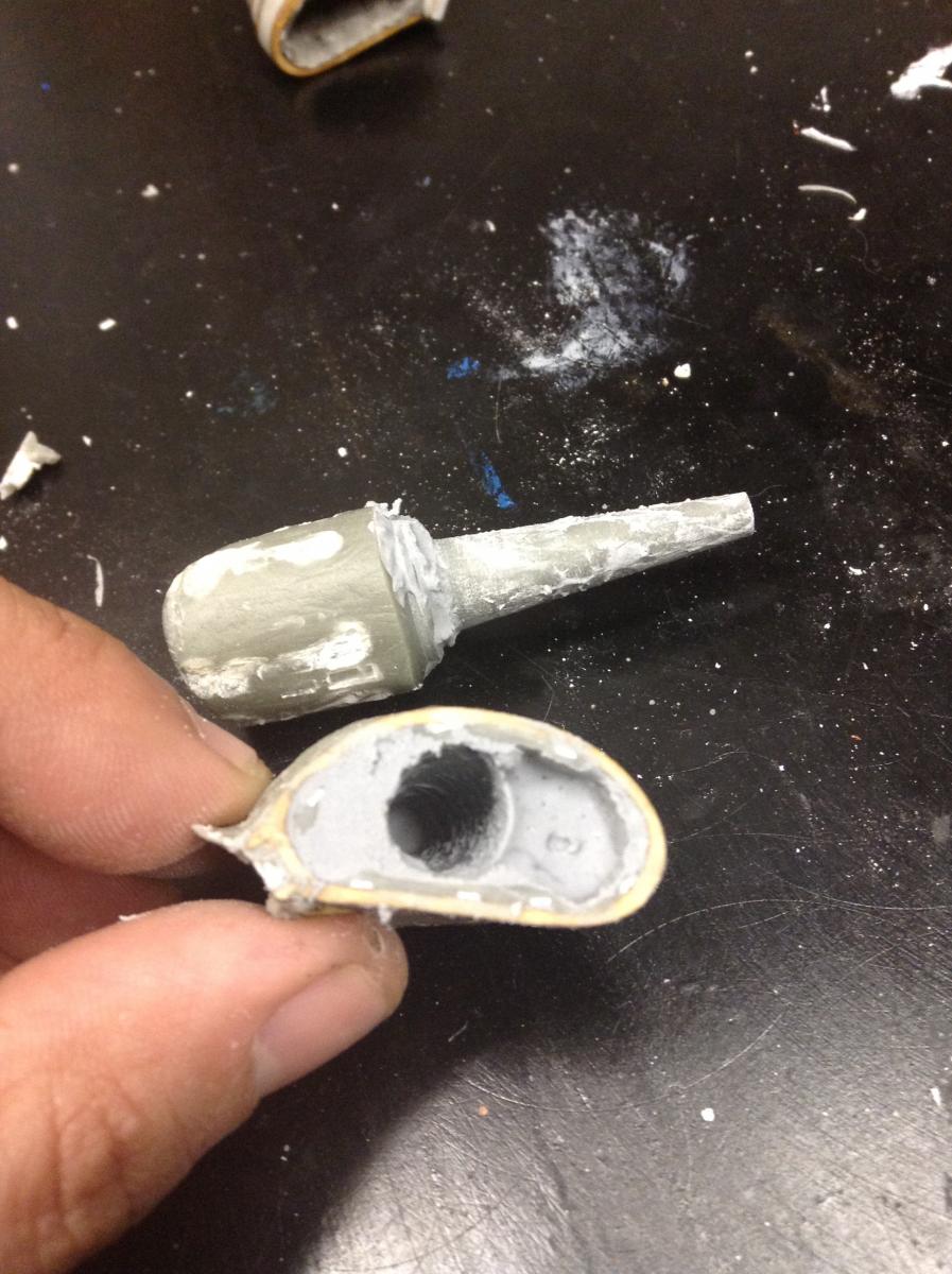
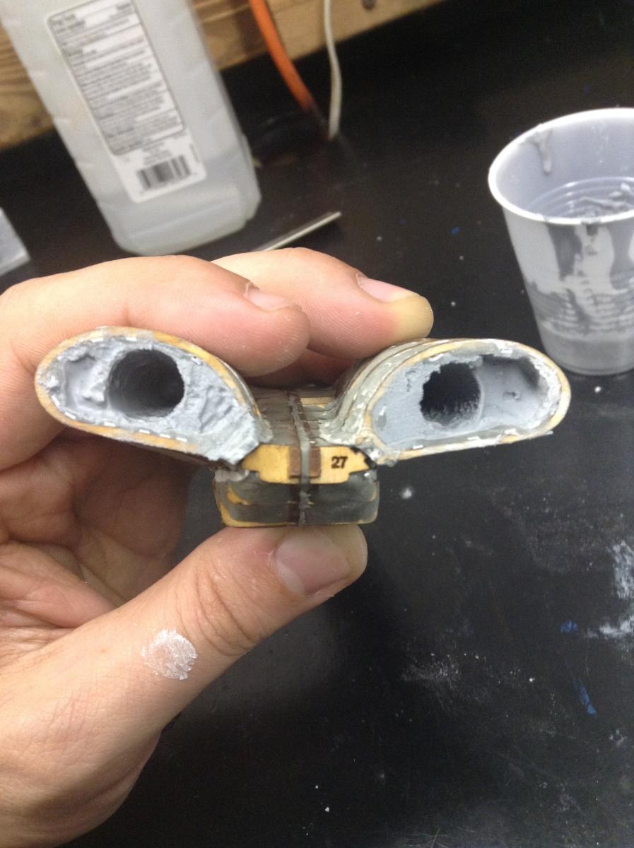
This update covers creating the center hole of the engine. The front of the engine was covered with putty.. I went ahead and cleaned up the front while the putty was curing. I noticed I could trim about 1/4" from the cone length to increase the diameter of the hole. Once this was done, I had to trim away some putty from the inside of one of the engines to allow the cone to hit the front. The engine was filled with dental stone and tapped gentle to make the sure the engine was full. The cone was inserted into the engine. The pushed out stone was removed while the stone sets. Once the stone is almost set, close to compact wet sand, the cone was given a slight twist and pulled out. The holes are not perfect but it should be easy to smooth out. The right engine needs additional stone/putty to fill in the remaining portion of the engine since I didn't make sure the engine was full before inserting the cone. My next step is to complete the hull and engines shaping.


-
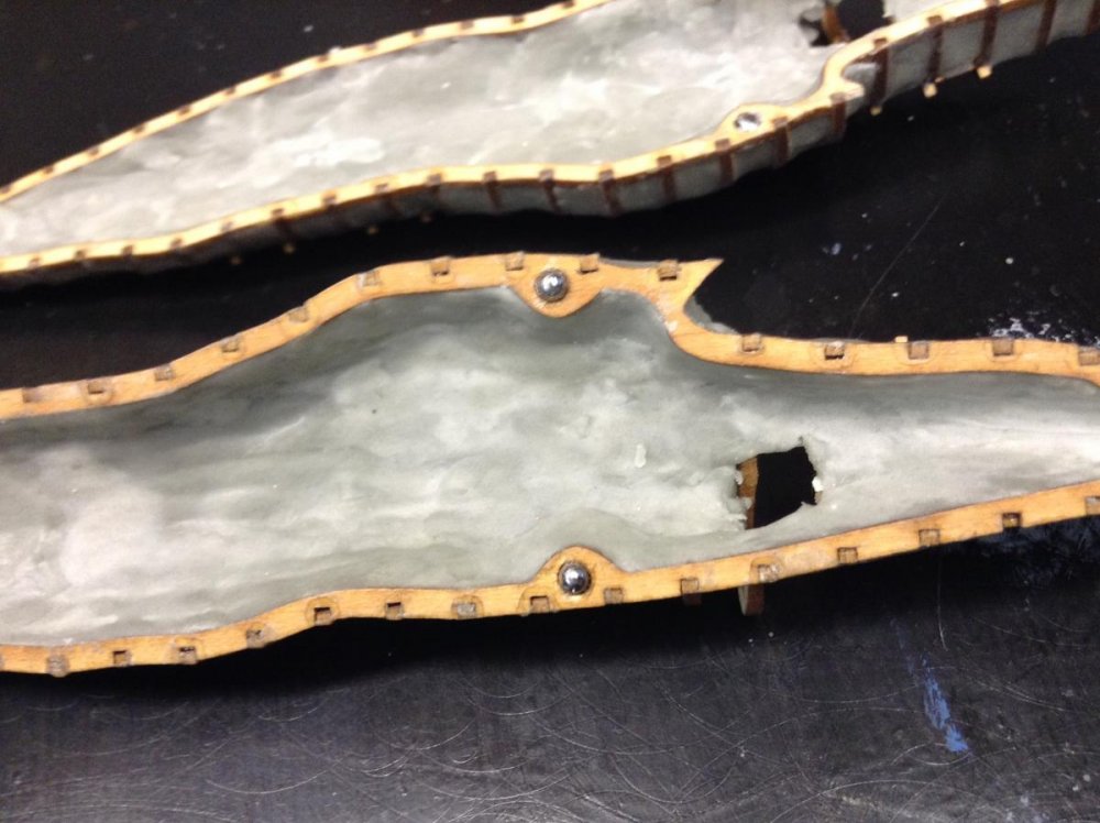
This update covers the steps I took to correct the gaps when the two hull halves are joined. I bought 1/8" steel ball bearings for guides pins. I cleaned out the guide pin holes on both hulls. The ball bearings were glued in on one of the hulls and Vaseline was applied along the hull edge including the bearings. Apoxie putty was placed along the areas where the gaps are located in the front and back. The hull halves were joined and pressure was applied until the center was together. Excess putty was cut away from the outside of the hull. Once the putty was almost cured, I pried open the hulls and cleaned up the new joint since it is easier to cut away the excess putty when it is almost cured. Once the putty is fully cured, I will be able to finish the clean up of the new joints. The next post will cover the filling of the engines.

-
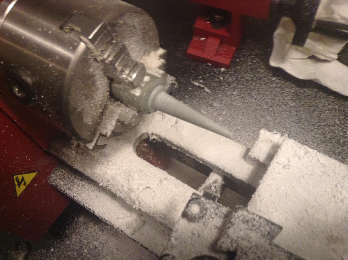
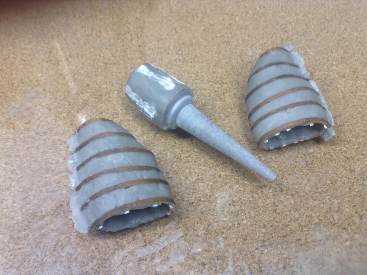
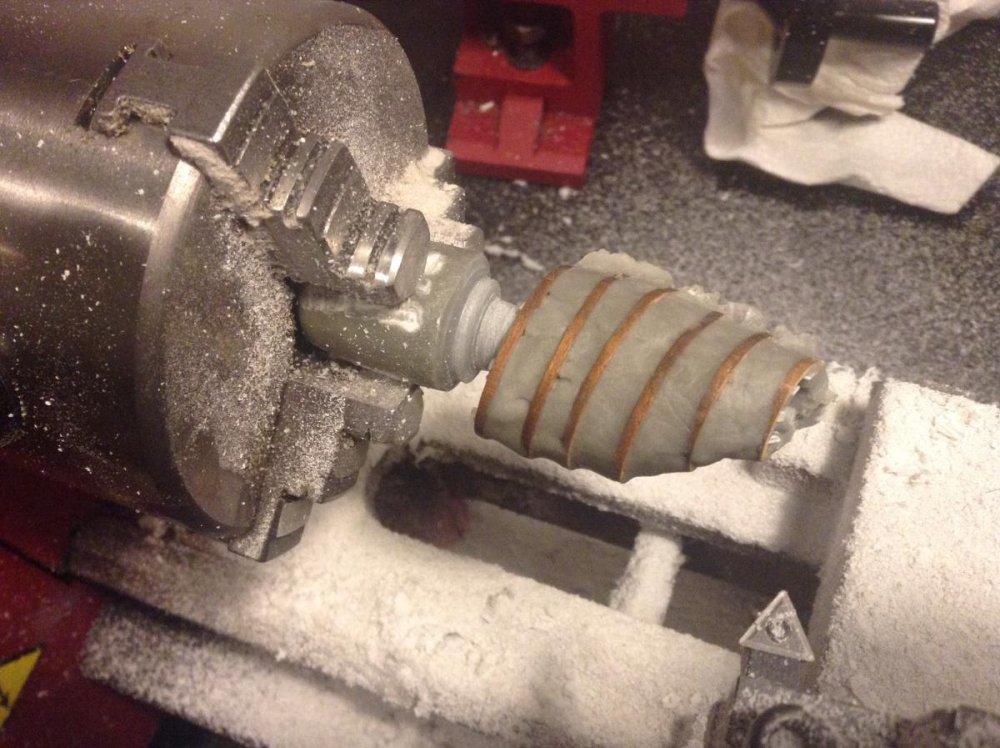
I had some time after work to turn a cone out of Apoxie Sculpt. It machines well. The pictures show the part in the lathe, a test fit with one of the engines and the part next to the engines. I think I can just use the cone with a coat of Vaseline instead of making a silicone version of the cone when filling in the engines. My next step is to clean the lathe.


-
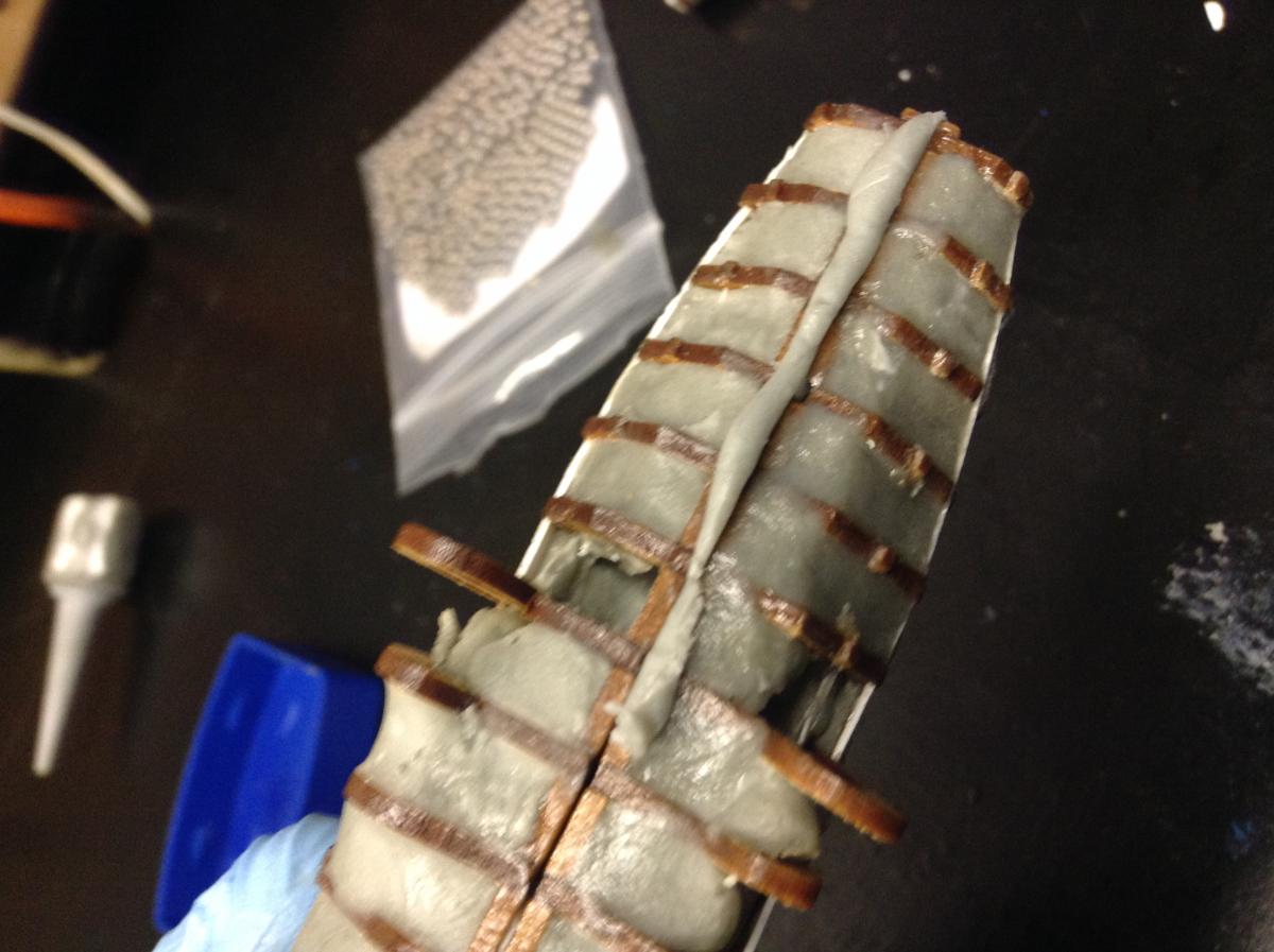
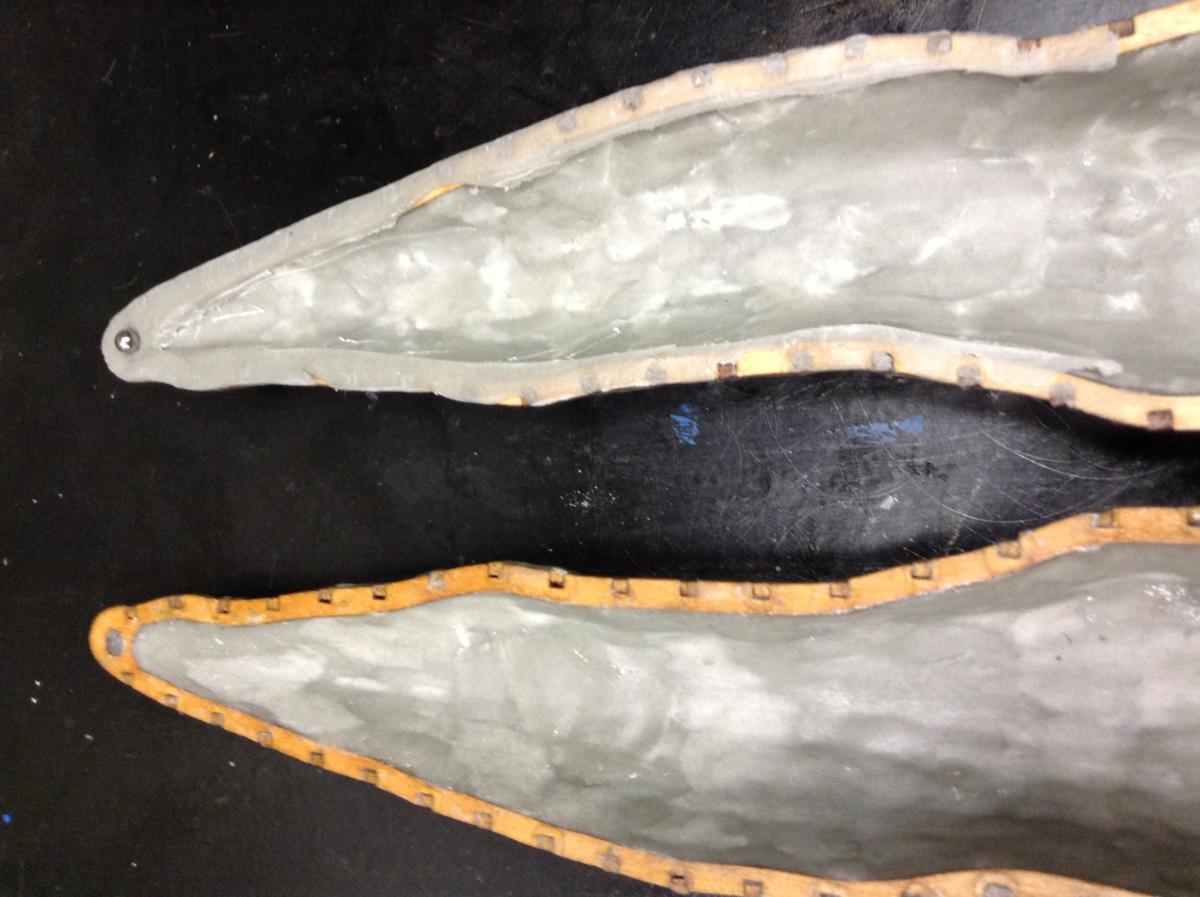
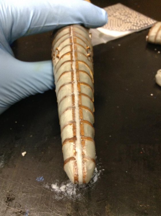
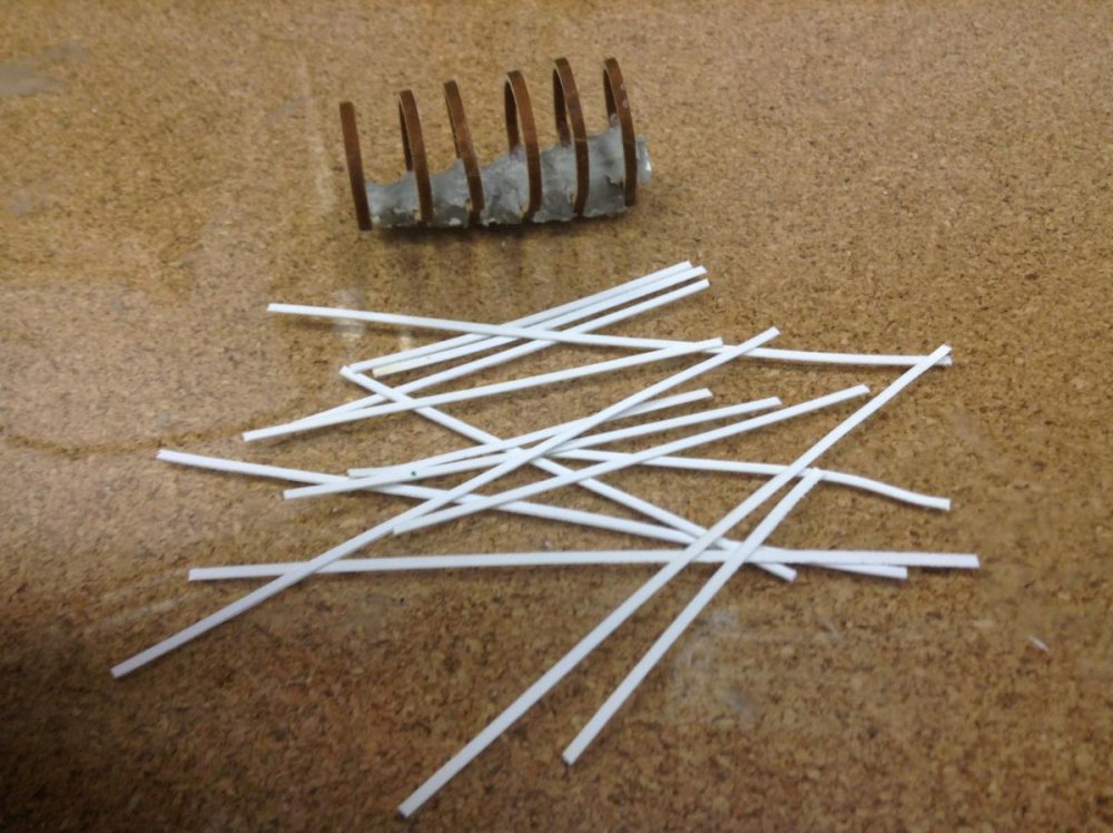
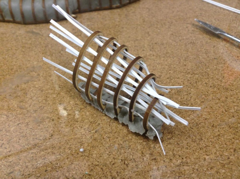
The engines are roughly filled in on the inside and outside. I used the same technique as I did with the hull. I glued on stringers and placed a thin layer of putty on the inside. Once the inside layer was cured, I followed up with a layer of putty on the outside. The next step with the engine is to make a silicone cone to place inside the engine and pour dental stone to fill in the inside of engine around the cone. Hopefully, this will make it easier to mold and cast the engine.


-
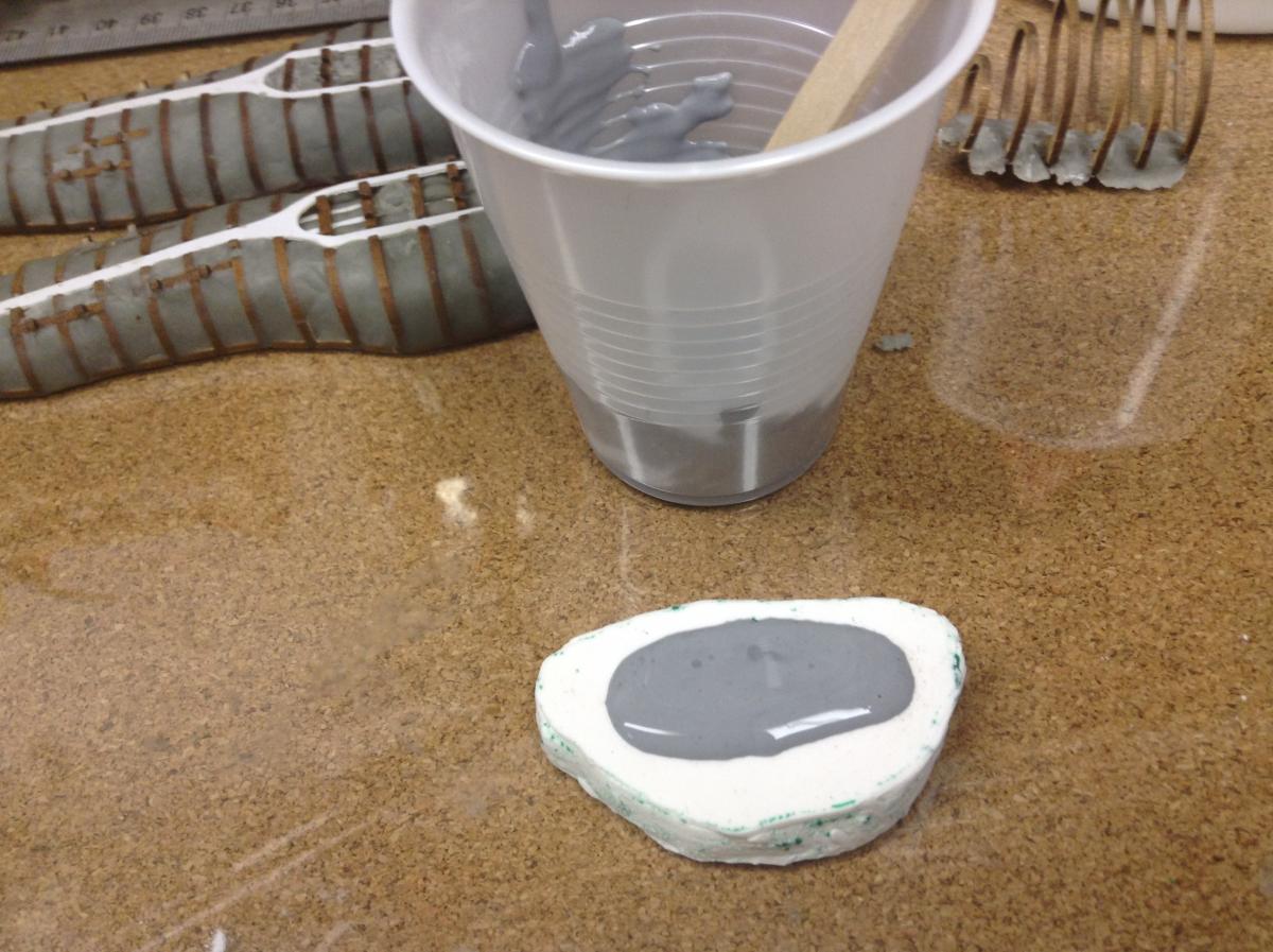
After going through the garage work shop, I couldn't find the mold I did awhile back for the side pod so I made another one. The pictures shows the sequence of making a single piece mold. I casted the pods in dental stone. It's easy to mix and pour and is very durable to work with. The next step is to come up with a plan to either use or don't use the alignment pins on the hull when attaching the pods.


-
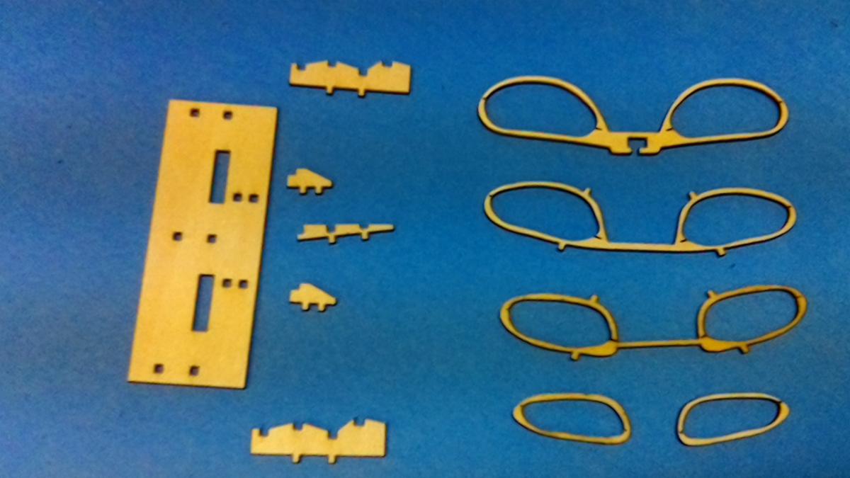
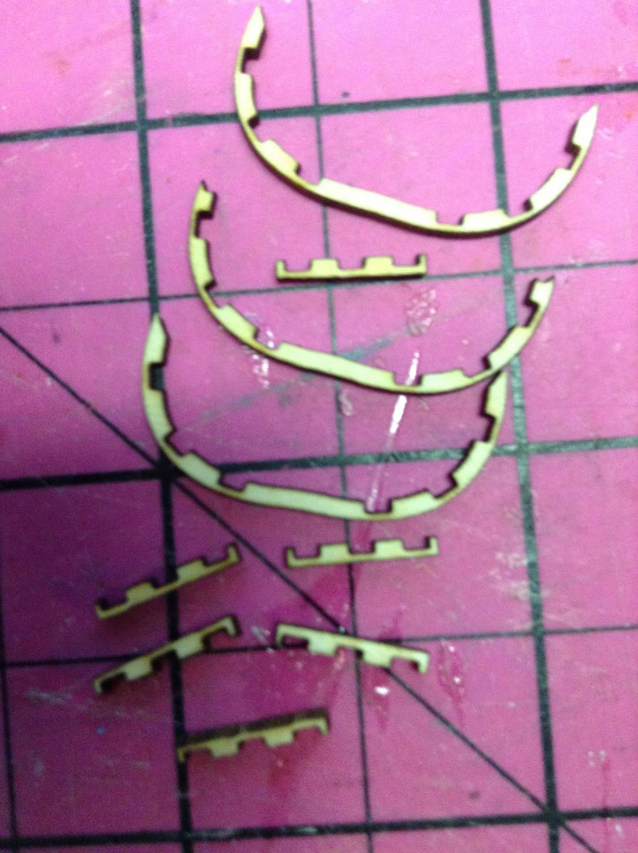
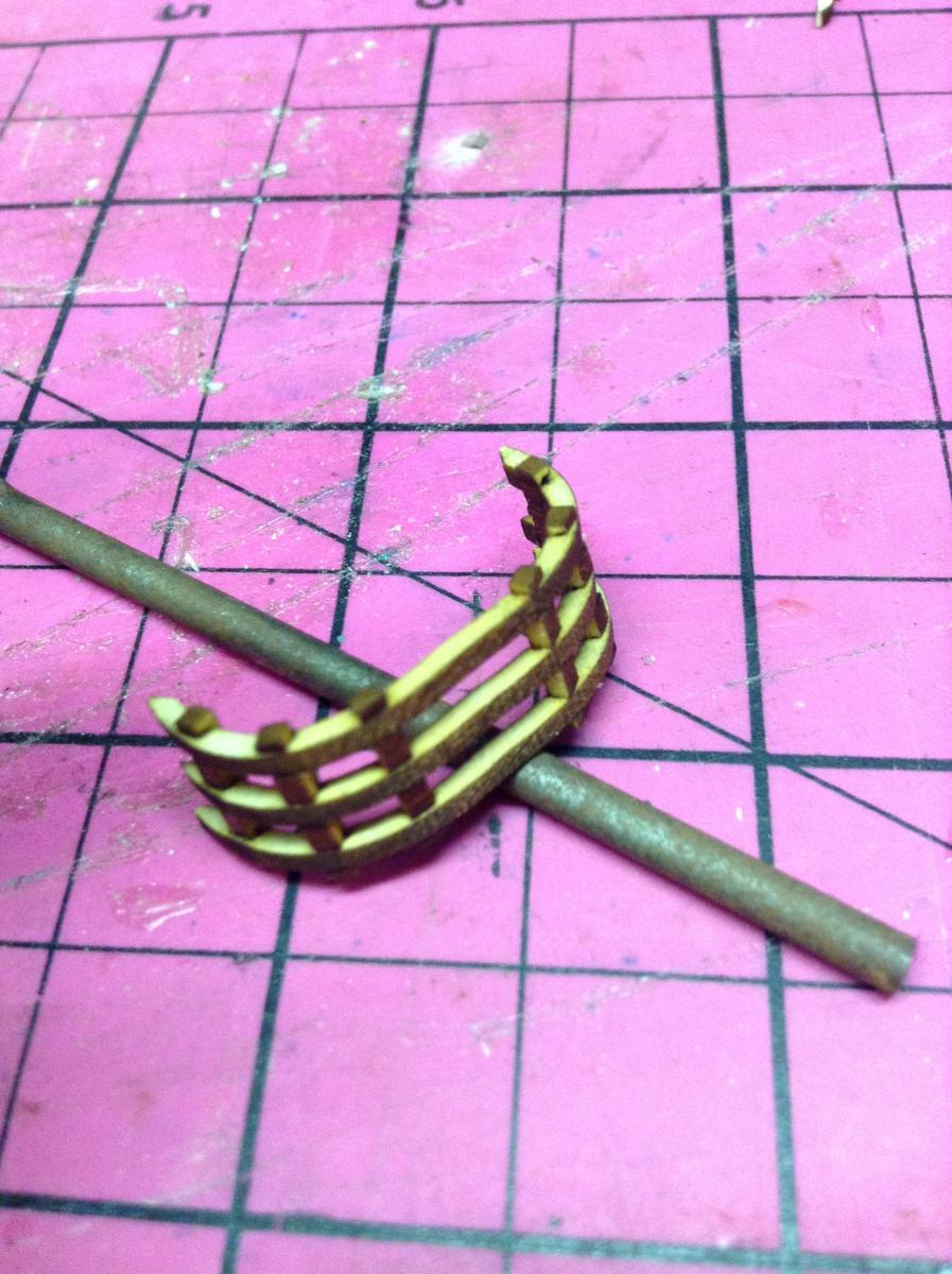
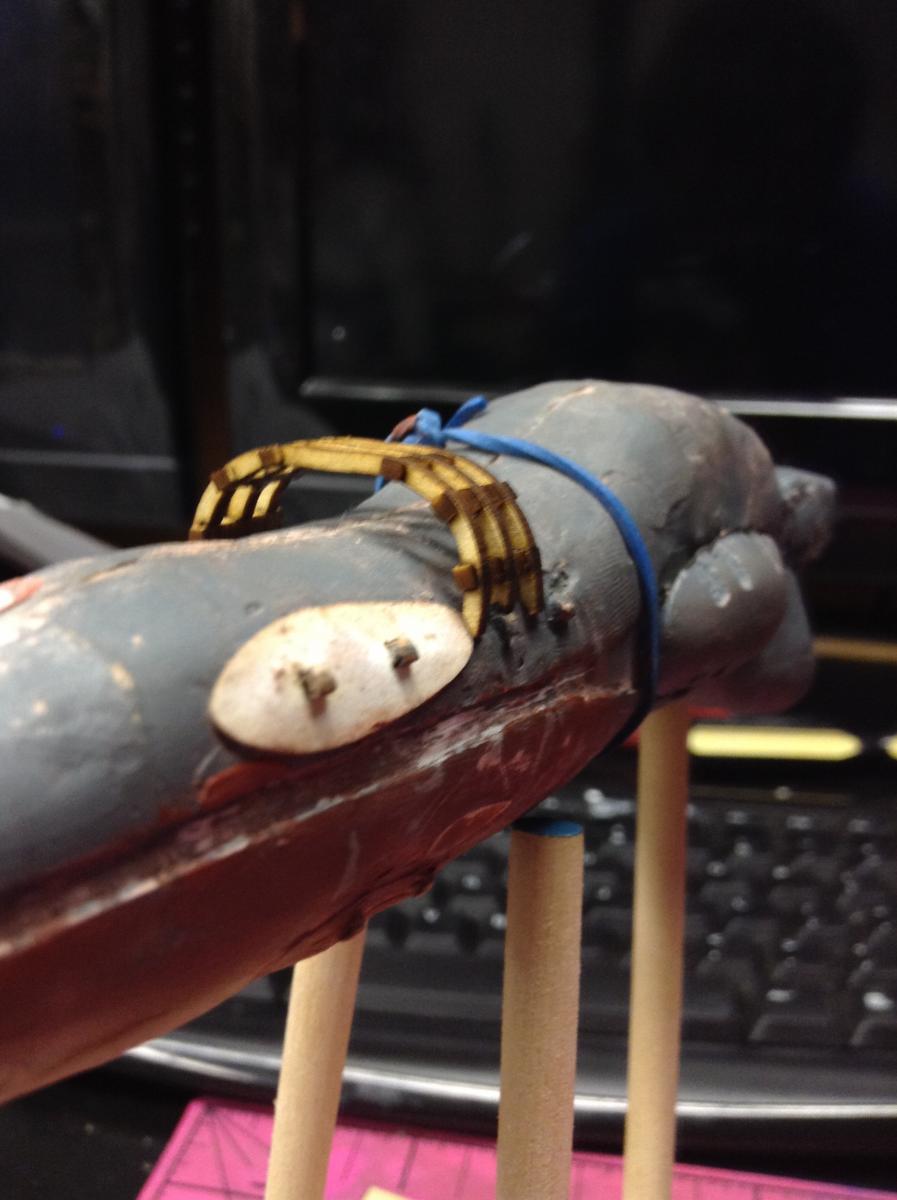
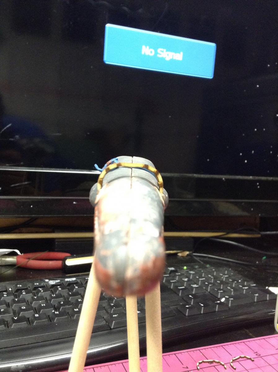
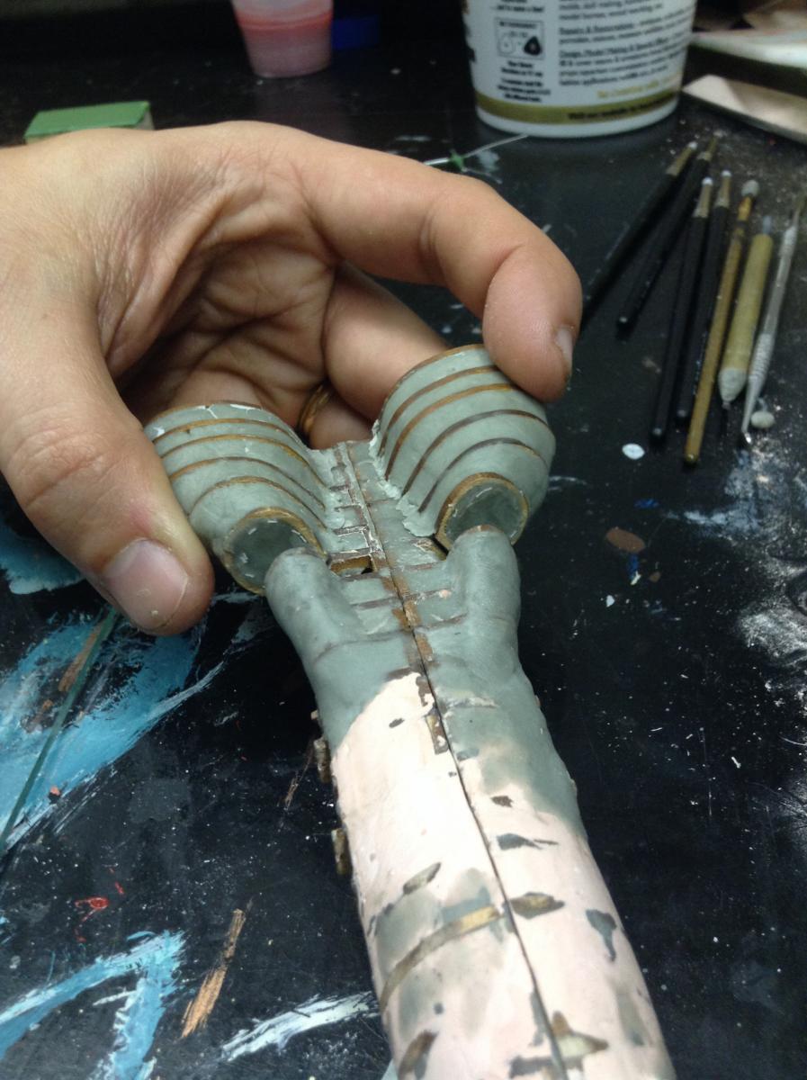
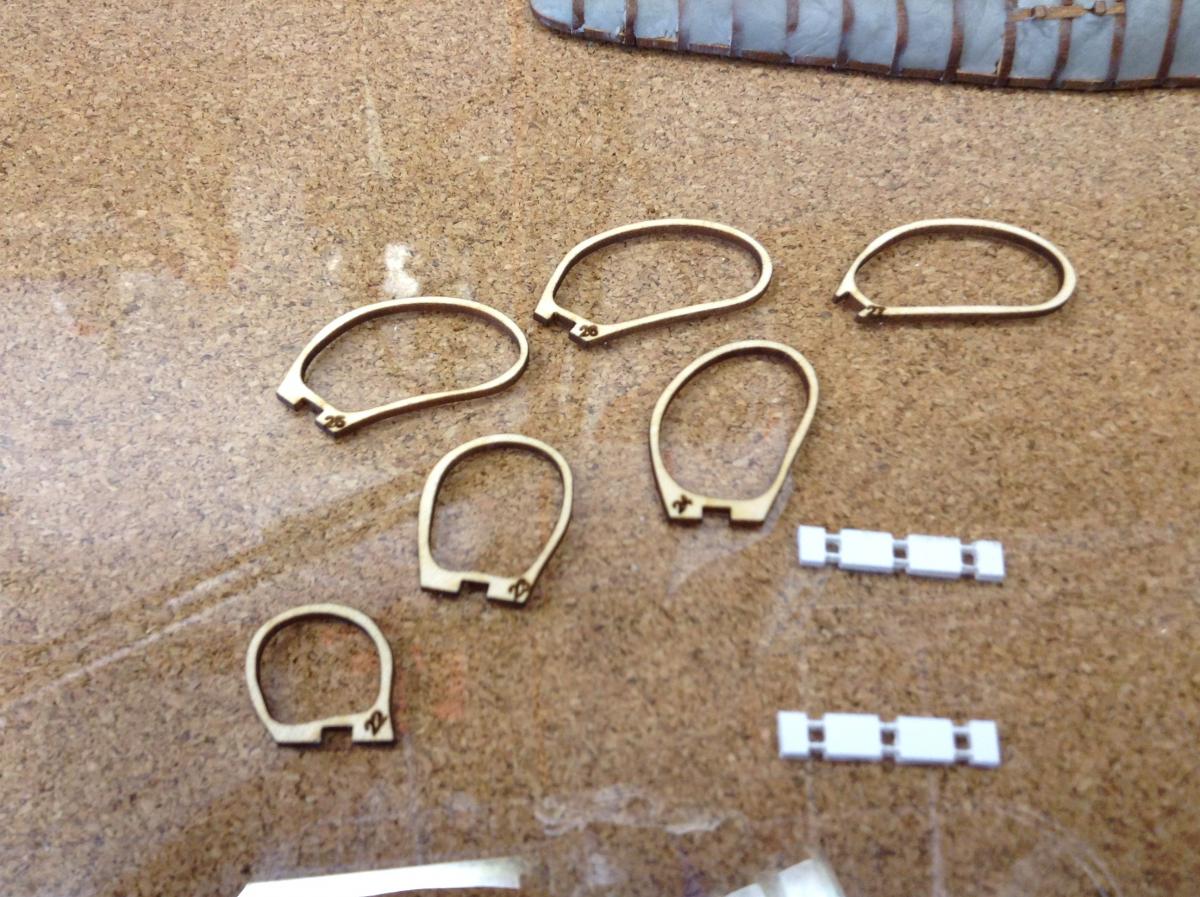
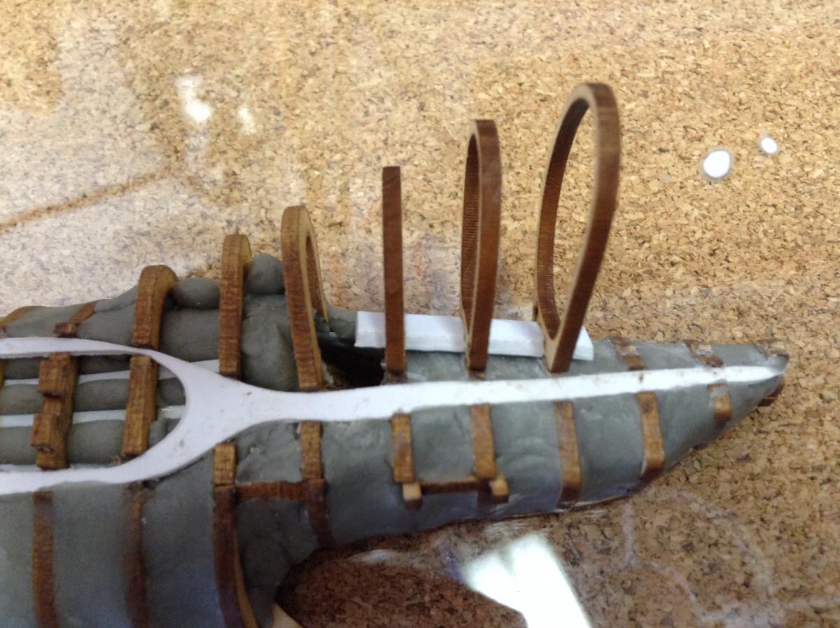
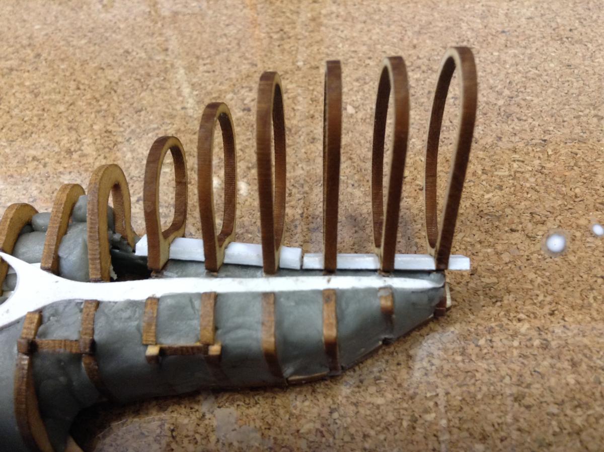
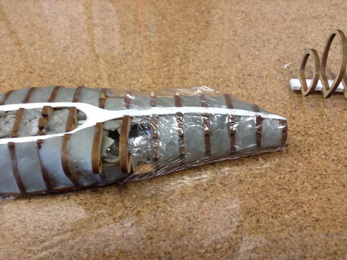
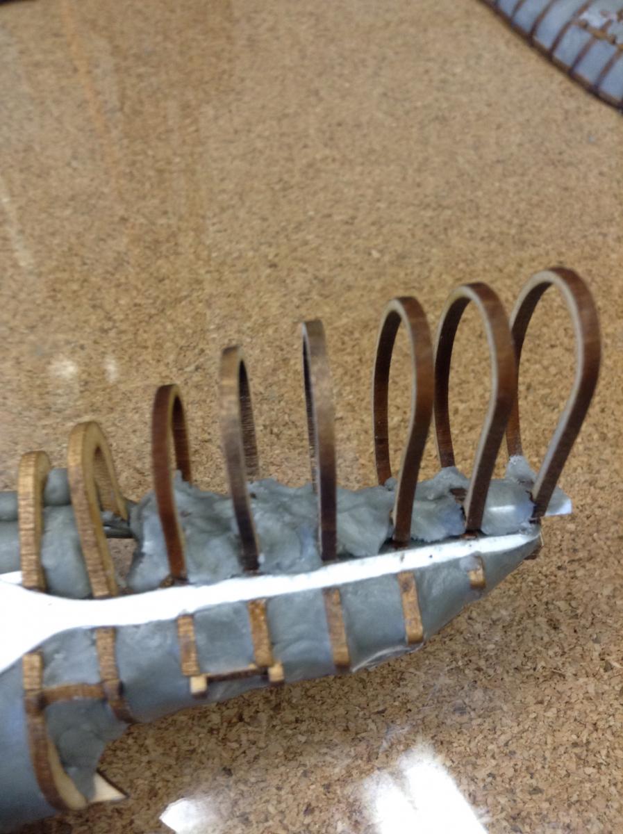
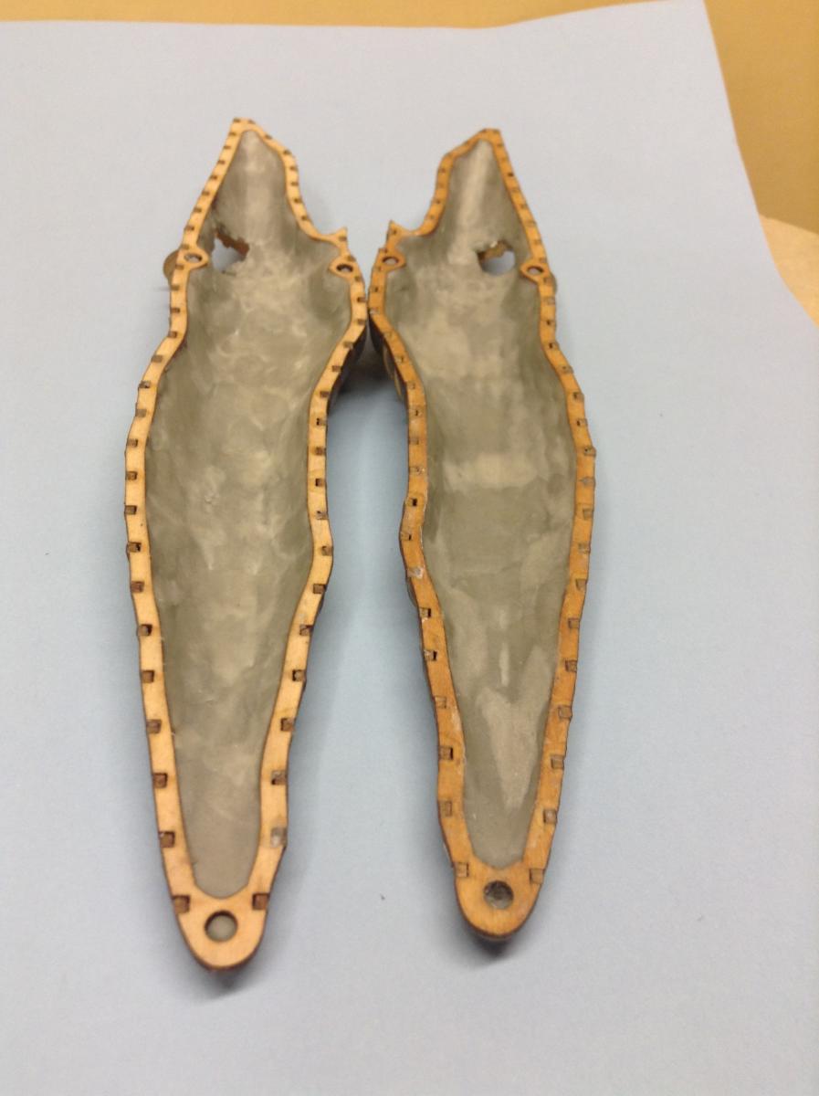
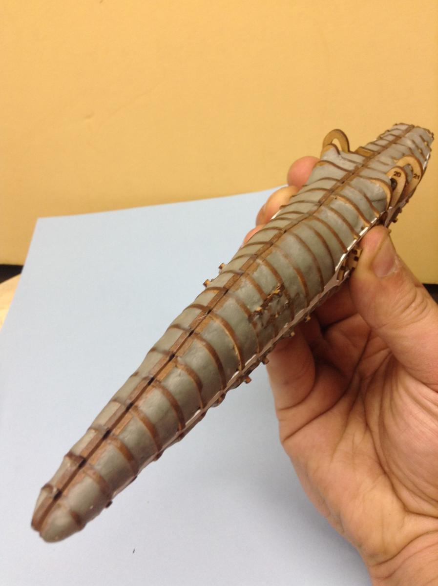
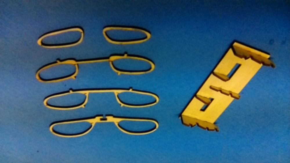
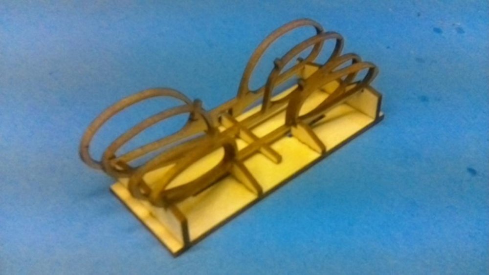
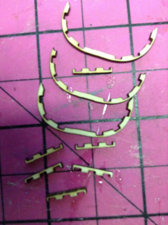
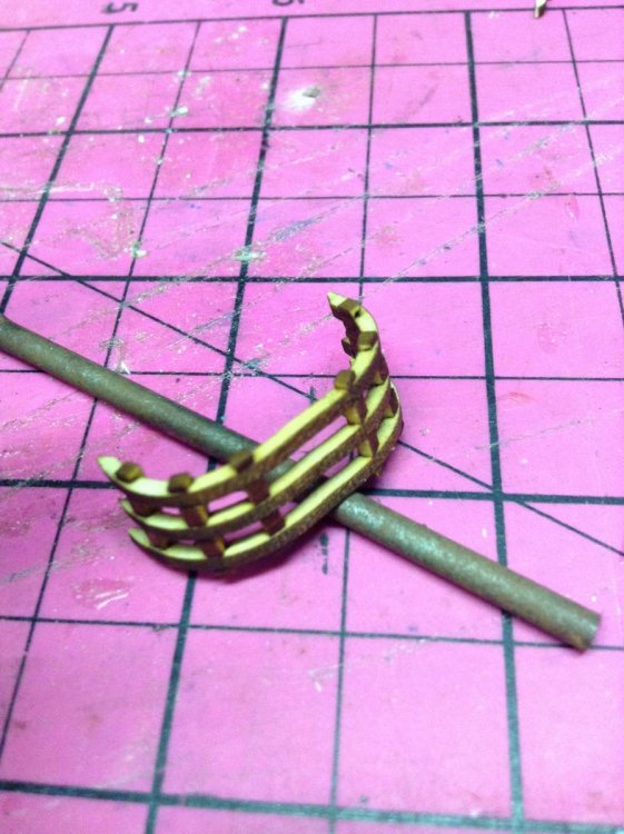
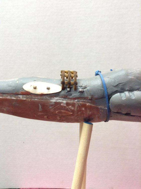
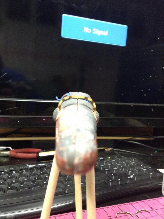
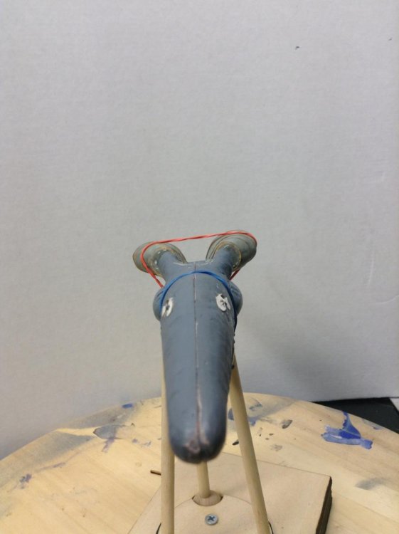
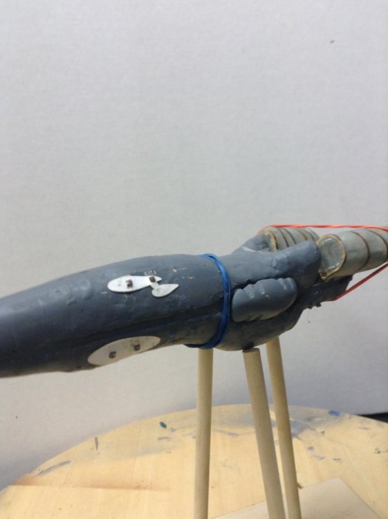
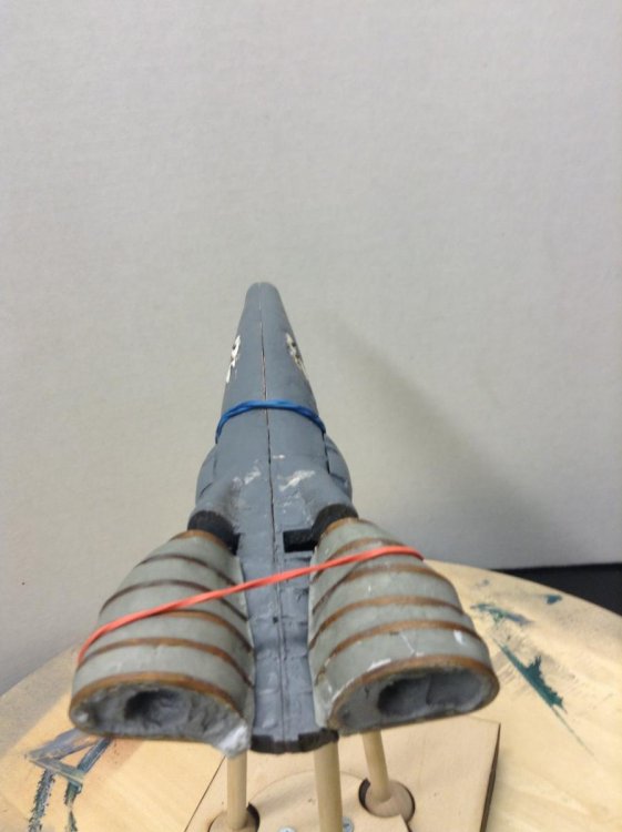
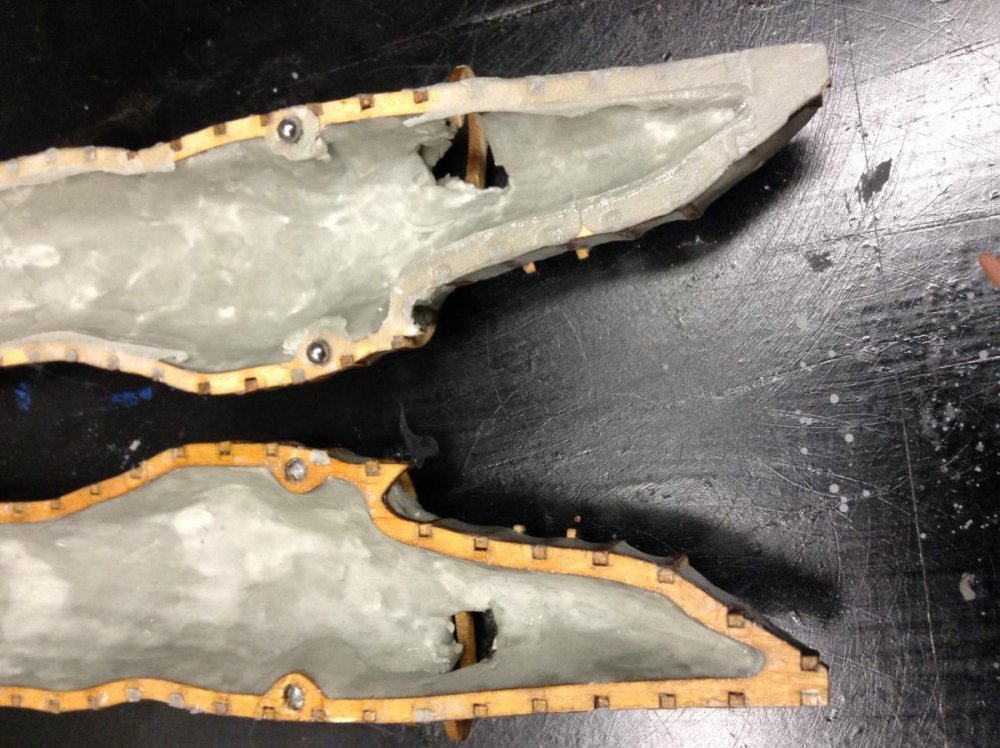
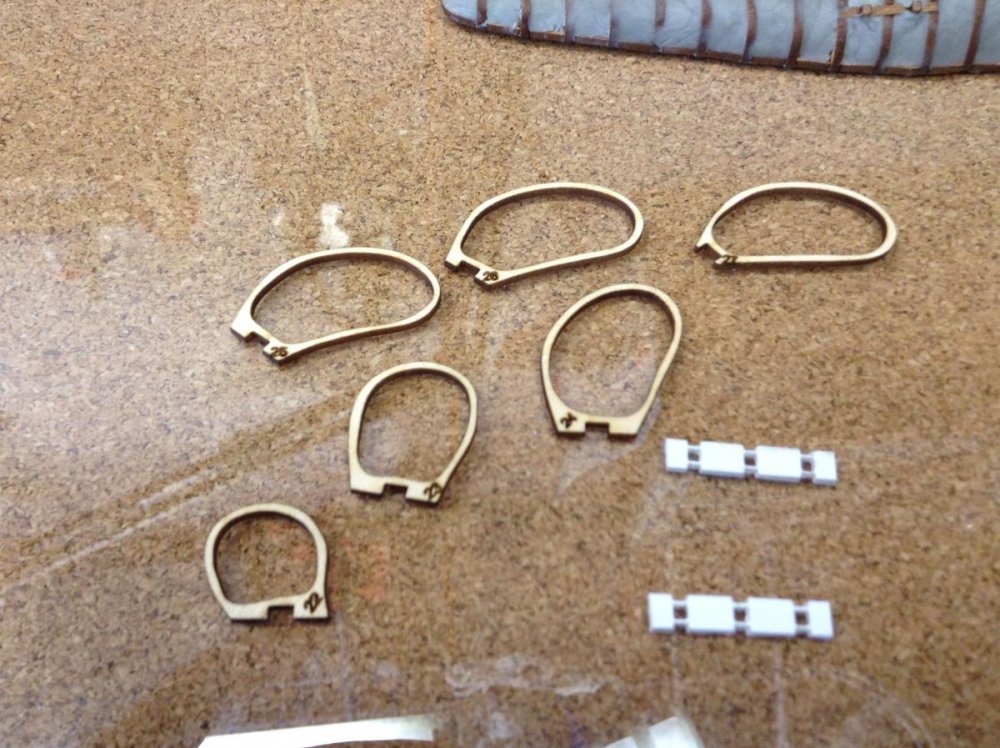
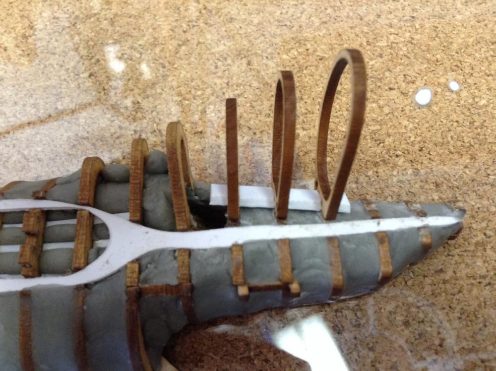
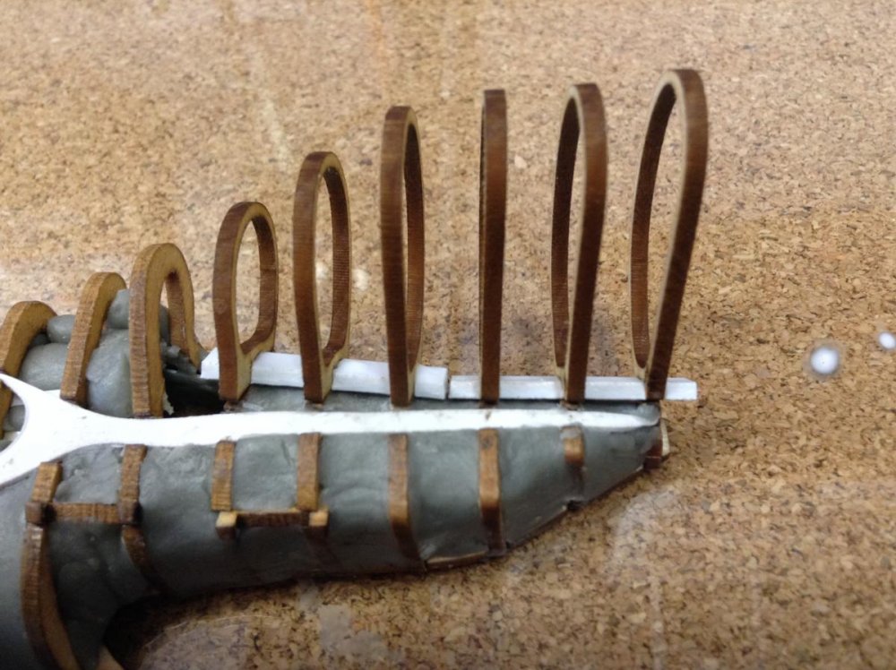
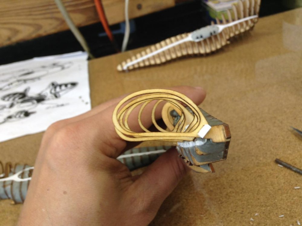
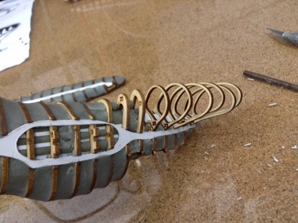
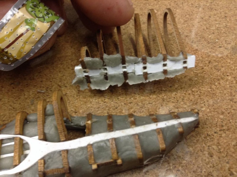
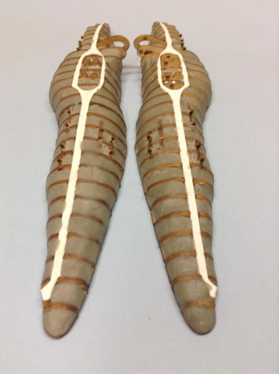
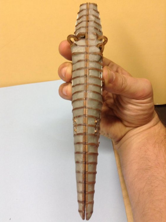
I managed to laze out two of the engine alignment plates with lots of fast, low power passes. Thanks MT! So once I had all the pieces ready to assemble the engine, the plate wouldn't align with the hull pins as a single piece. The pins were not in a straight line. This was most likely an error in my CAD design. So I split the plate in two to solve this problem. By doing this, the plates mostly stayed flush with the hull ribs. I did have to use the heat gun on the places where the plate didn't stay completely flushed. The next step was to glue the ribs onto the plate. No major problems there. I did try using saran wrap shrunk on to the hull with a heat gun. My reasoning for trying the saran wrap was my attempt to avoid placing a release agent (Vaseline) on the hull. The wrap kept moving when applying Apoxi Sculpt. I imagine if I tried a couple more times with the saran wrap it would of worked but I switched over to using Vaseline as a release agent. I covered the plate with putty to lock the ribs on to plate and to blend with the hull. Once the putty cured, I gently pried the engine from the hull. So the next stage is to glue stringers on the inside of the engine like I did with the hull and lay down the first inside coat.


-
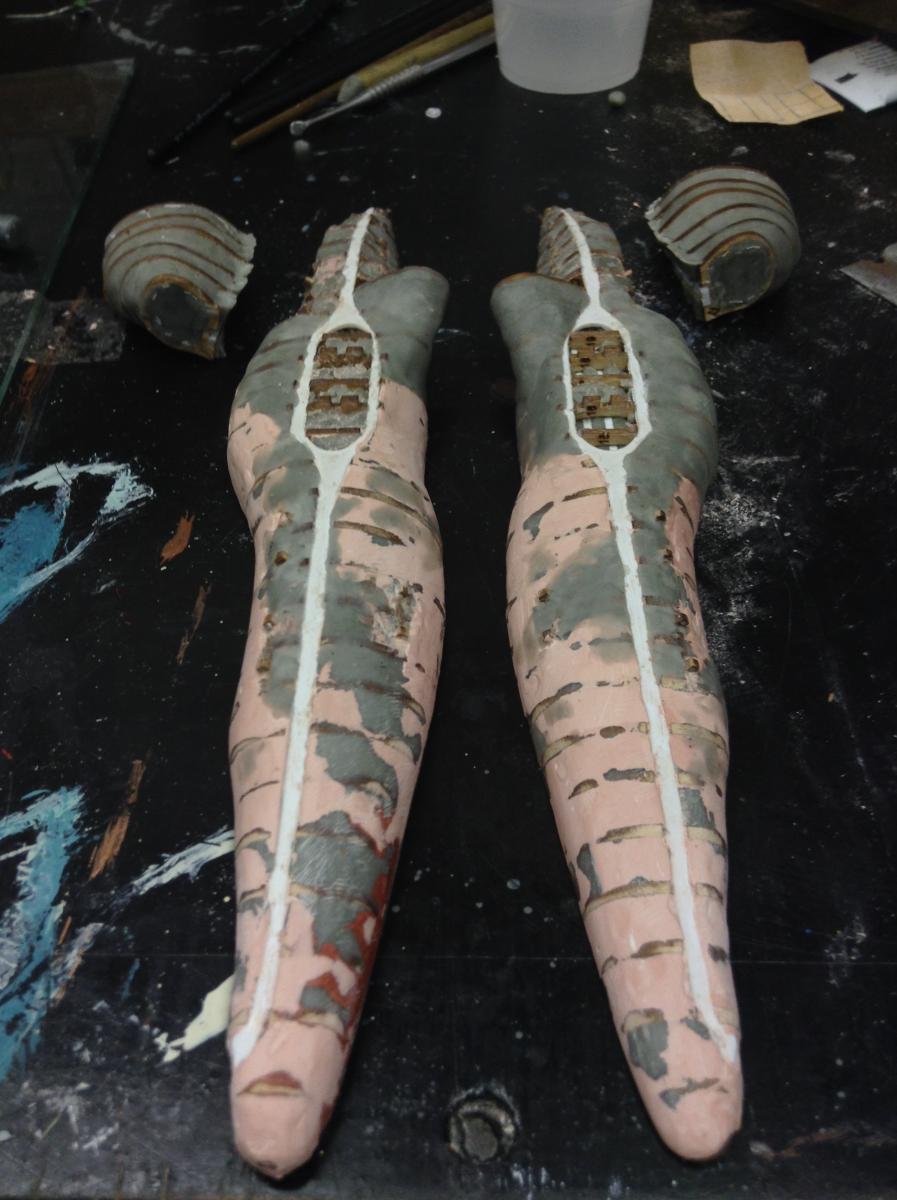
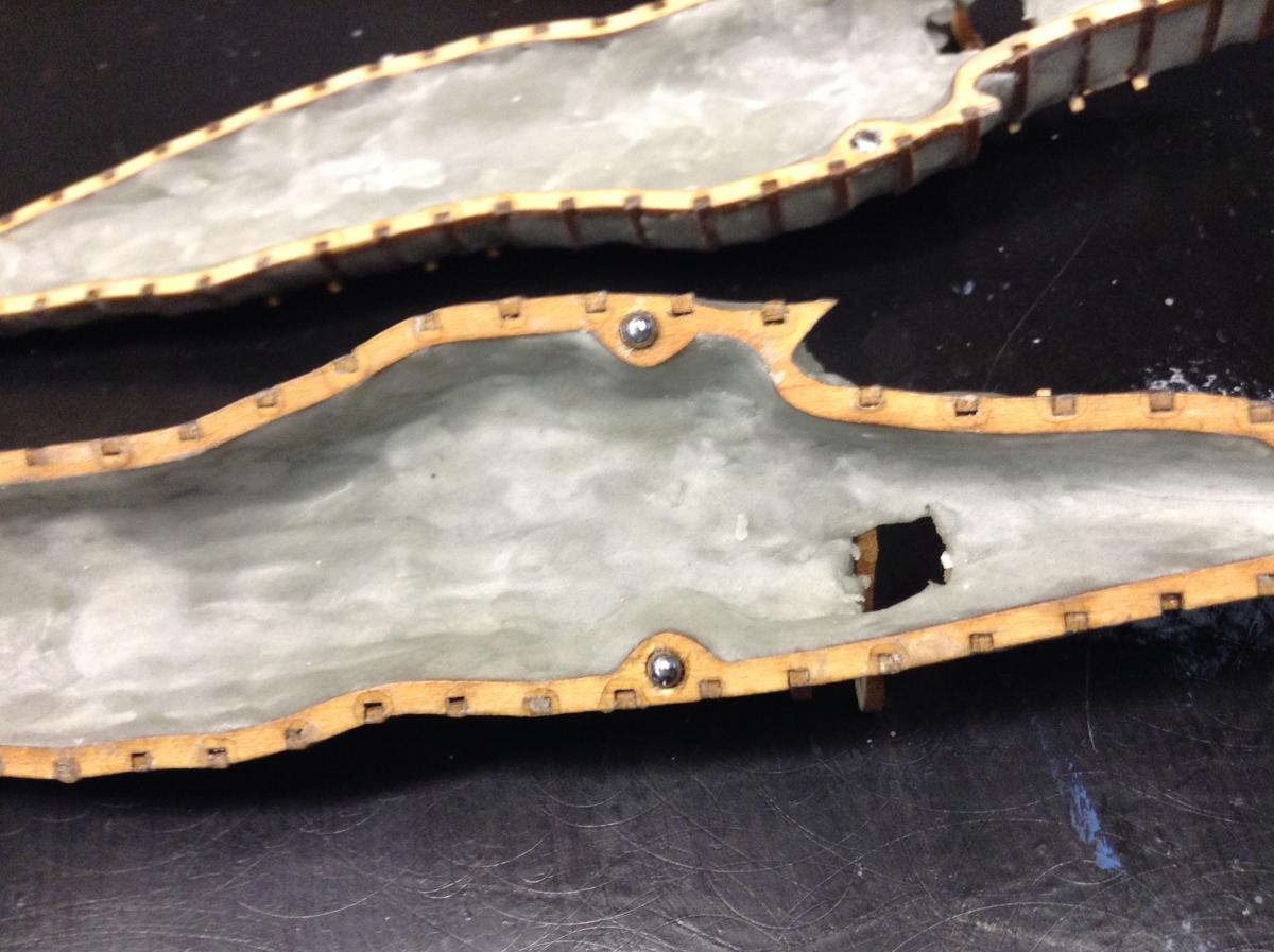
The inside of the hull is almost complete. I still need to install the hull alignment pins and complete the hole to the engines. There will definitely be minor touch ups or corrections as I get closer molding and casting the hulls. The outside hull is roughly filled in. I wanted to wait until there was a solid foundation to work on when smoothing the hull with the ribs. One of the very small alignment pins for one of front side pods broke off. I can still align with the one pin. In the pictures, you can see the hull is not perfectly flat. I think I can eliminate this by sanding the hull on a flat surface until the gap is gone. This will be the first thing done before I continue on with the rest of the hull. Now for the engines. There is an alignment plate (polystyrene) that will need to be heat and pressed against the hull. Unfortunately, I couldn't make it a flat plane from front to back. There is a twist due to the hull and engine profile. I am going to attempt the boiling water technique. First time trying it so wish me luck. Once the plate is in place I can set the rest of the engine profile ribs on this plate. Then I can sculpt and blend the two separate pieces to make the engine and the rest of the hull. The last portion of the engine will be tackled once these two pieces are done.


-
This is truly great work. The level of detail and the use of different materials to achieve what you are striving for is inspiring.