Jawjaw Posted March 4, 2004 Share Posted March 4, 2004 Thanks for hooking up wm cheng, myersjesse. I have been looking forward to the next buildup for a long time. I am very excited to see how this one will turn out. I hope you build the SV-51 when it comes out, wm cheng. I would be more than happy to pitch in a few bucks if we were to take a collection. Quote Link to comment Share on other sites More sharing options...
Gerwalker Posted March 5, 2004 Share Posted March 5, 2004 William, as always: Thanks!! I love the way you tell and show us even the minimum construction details. I have just one thing to say so far (I ussually try not to interrupt your posts with comments): I've been using the silver marker technique for a while to reproduce lighst and reflectors since it is one of the best silver paints. BUT warning: the solvents used in those markers are ussually very strong and tend to eat the plastic. Applying the paint with a brush as William does is the safer way to go since you can adjust the ammount of paint being applied. I had some bad experiences with a couple of lights in my Hase VF-1 battroid when I made a pool of paint (I used the marker's fine tip to apply the paint) on them: the plastic just dissolved... Quote Link to comment Share on other sites More sharing options...
wm cheng Posted March 5, 2004 Author Share Posted March 5, 2004 Hey thanks Gerwalker for the tip - I didn't know the paint marker was corrosive to plastic, I will have to watch out for that (you see, you learn something everyday) Thanks, I would like to learn tips from all of you (feel free to interrupt the thread - it shouldn't be me preaching - its a conversation, I'd like to get something out of it too ) I am hoping to get in a day (or maybe a day and a half) this weekend (at work now ) Quote Link to comment Share on other sites More sharing options...
wm cheng Posted March 7, 2004 Author Share Posted March 7, 2004 Hi all, got another 2-3 hours in tonight - yipee! I ran out of my old Microscale liquid masking film, so I am tring this new stuff from Japan (if its Japanese it must be better? ) made by the same Mr. Surfacer people. Its a bit thick - anyone know of a thinner for this stuff? Quote Link to comment Share on other sites More sharing options...
wm cheng Posted March 7, 2004 Author Share Posted March 7, 2004 I've sanded down the areas I filled in with the styrene sheets and the little injection pin depressions. All I have used so far is Mr. Surfacer 500, there was nothing significant yet that required putty. Quote Link to comment Share on other sites More sharing options...
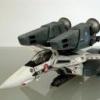
wm cheng Posted March 7, 2004 Author Share Posted March 7, 2004 Another test fit with the wings in place, you can see how little sanding and filling was really required, there isn't a lot that is exposed (and this is the worst case when the wings are fully swept forward) Quote Link to comment Share on other sites More sharing options...
wm cheng Posted March 7, 2004 Author Share Posted March 7, 2004 This area always bugged me - those really "thick" squared off edges don't look very realistic or "aircraft-like". Plus this gap seems rather large considering that the wings are fully swept back. Quote Link to comment Share on other sites More sharing options...
wm cheng Posted March 7, 2004 Author Share Posted March 7, 2004 Here's the forward section in the worst case with the wings fully swept back - you can see the little styrene card and the Mr. Surfacer around the edges that is now sanded smooth. Quote Link to comment Share on other sites More sharing options...
wm cheng Posted March 7, 2004 Author Share Posted March 7, 2004 When its fully swept forward - you hardly see anything at all. Quote Link to comment Share on other sites More sharing options...
wm cheng Posted March 7, 2004 Author Share Posted March 7, 2004 I've decided to sand these areas down, to give an airfoil profile to them so that they would appear thinner in the end. (Here is the before shot) Quote Link to comment Share on other sites More sharing options...
wm cheng Posted March 7, 2004 Author Share Posted March 7, 2004 Here's the after shot, after I sanded down the edges and smoothed out the contours (sorry for the fuzzy photo - the camera had a hard time focusing so close) Quote Link to comment Share on other sites More sharing options...
wm cheng Posted March 7, 2004 Author Share Posted March 7, 2004 Of course I had to re-scribe the panel line details that were lost when I rounded over the edges (I used the Hasegawa Tri-tool microsaws for this job - they are tiny photo-etched saws - you can buy them from HLJ) They are invaluable in recovering lost panel lines especially around seams and filled joints. Quote Link to comment Share on other sites More sharing options...
wm cheng Posted March 7, 2004 Author Share Posted March 7, 2004 Here's that "dreaded" intake area on the chest plate. Hmm... not so bad (I think Valkyrie's exaggerating just a bit ) don't be scared off, it not really that bad. I didn't build any of it up or perform any type of modification, I just dabbed a few coats of Mr. Surfacer 500 at the two ends - I could of used a bit of putty, but the areas are so small that needs filling. Quote Link to comment Share on other sites More sharing options...
wm cheng Posted March 7, 2004 Author Share Posted March 7, 2004 Come ON ( don't fear monger)!! that was the worst side, this side is even better. This is nothing , you should build some old Revel or AMT/ERTL kits, they've got seams that you could launch missles through! This kit really is up to Hasegawa standards so far, this portion is the worst fit of the kit thus far, but I haven't even had to break out the putty yet, all I've been using is Mr. Surfacer 500 so far. Mind you, on the bigger seams I've put a few coats on (after each coat dries). Quote Link to comment Share on other sites More sharing options...
wm cheng Posted March 7, 2004 Author Share Posted March 7, 2004 Since therew is so much gap when the wings are fully swept back - you really can see right into the cavity of the fuselage. Again, I broke out my ribbed styrene sheet and cut little "fences" and glued then in place - being careful not to obstruct the swing extent and gear mechanism of the wings. Ah, the ribbed sheet make it look like some kind of retracting baffle system. (Hey David, what's on the real F-14 or F-111 - is there anything that seals up this opening when the wings extend fully?) Quote Link to comment Share on other sites More sharing options...
wm cheng Posted March 7, 2004 Author Share Posted March 7, 2004 Here you can see the rounded over edges and the bit of baffling I added in the opening with the wing fully swept back. Quote Link to comment Share on other sites More sharing options...
wm cheng Posted March 7, 2004 Author Share Posted March 7, 2004 Ah! look, when you glue those little cranked arrow bits or mini-forward canards (correct my nomenclature if you will David) they hide even more (if any sins) of those dreaded intake connections. Quote Link to comment Share on other sites More sharing options...
wm cheng Posted March 7, 2004 Author Share Posted March 7, 2004 Onto the next steps, I've decided to fill in these injector pin depressions now, since it would be difficult to sand them later when the halves are glued together. Quote Link to comment Share on other sites More sharing options...
David Hingtgen Posted March 7, 2004 Share Posted March 7, 2004 (edited) Ah, AMT/Ertl. Nothing like gluing 3 strips of styrene together, to get a thick enough strip to fill a gaping trench... ::edit:: Tornado's, B-1B's, most any swing-wing plane etc, use inflatable air bladders to fill the gap when the wing's fully forward. Yes, neat arrangements of panels and doors would look better, and they always try it, and they always get messed up. So they just use big inflatable bags. Basically, one above, and one below. As the wing "exits" the area by sweeping forward, they progressively inflate to seal the gap. B-1B's and Tornado's are by far the easiest to see, I'll find some pics later. F-14's are very hard to see, due to the shape, the cover over it, the sealing plates above, and the fact that the wings are always swept back at every airshow, otherwise I'd have my own pics of the F-14's system... F-111 seal: http://www.clubhyper.com/reference/f111indetailjr_3.htm Note the pic with the extended wing, pointing out the hinge line with an arrow. The whole panel aft of that pivots up and down about that hinge to open and close the gap, inflating and deflating the grey airbag as it does so. This is how most every plane does it. When the wings are back, the bags are deflated and the panel is lowered flush to the surface. When forward, panel lifts up and bags inflate. (Yes, it seems kind of backwards, why not just always keep the moving panel down flush---there's some aerodynamic pressure shift caused by the change of wing position, and the moving panel takes care of that) PS-- I'd call the triangular parts on the intakes a strake, though a large one. Almost an LEX, but not quite. Kind of like a streamlined version of how the F-15 uses its intakes like an LEX. Edited March 7, 2004 by David Hingtgen Quote Link to comment Share on other sites More sharing options...
wm cheng Posted March 7, 2004 Author Share Posted March 7, 2004 Here are the arm halves glued together - the grey is Mr. Surfacer 500 again - well will see weither this will be enough to smooth over both sides, becareful to try to align them so the hieghts match - this will save lots of sanding later on to even both halves out. Notice that there are a few areas where I have run the Mr. Surfacer across the direction of the seam - I've noticed a few slight sink depressions in those area and should be filled in. You really only have to concentrate on this lower surface, the other side will be mostly obsured by the top of the fuselage (lazy tip #2 ) Well, thats it for tonight, I"ll let everything dry overnight. A lot of sanding awaits me for the next few steps - the most boring and tedious part for me But it has to be done - if you skimp on this stage - you'll pay for it when you start painting - believe you me, I have had many dissapointments when I try to take short cuts during the sanding stage. Quote Link to comment Share on other sites More sharing options...
Captain Angel Posted March 7, 2004 Share Posted March 7, 2004 wow... must order kit... Anyway, what is this Mr. surfacer stuff? Primer? Filler? and how do you apply it, with a brush, or toothpick? Quote Link to comment Share on other sites More sharing options...
wm cheng Posted March 7, 2004 Author Share Posted March 7, 2004 Yes, Mr. Surfacer is like a very thin puttly or filler. It has the consistency of really thick paint - I would guess its really fine particles of filler suspended in some solution. Its great for filling in really tiny hairline seams. I have two types (I think there are more grades out there) there is a 500 for the coarse (gap filling) stuff and a much finer 1000 for the hairline cracks ad seams. I brush it on with a thin paint brush which is then cleaned with Mr. Color thinner. For small jobs, it better than putty since you can control exactly where it goes, and can run into the really fine seams. Quote Link to comment Share on other sites More sharing options...
wm cheng Posted March 7, 2004 Author Share Posted March 7, 2004 I am attempting to redefine or re-scribe the panel lines which run through the seams. When you use Mr. Surfacer and sand off - I occassionally sand too much off including the fine lines Quote Link to comment Share on other sites More sharing options...
wm cheng Posted March 7, 2004 Author Share Posted March 7, 2004 This nose area was tricky to re-scribe because of how small the first ring was - you can see a little bit of the Mr. Surfacer left in the seams doing its job in filling in fine seams. Quote Link to comment Share on other sites More sharing options...
wm cheng Posted March 7, 2004 Author Share Posted March 7, 2004 I sanded away the circular injection pin depressions and have decided to paint this intake area in a sky grey. What I will do later is airbrush the white/off-white grey overcoat and gently feather it back revealing this grey inside the intake fans - this gives the illusion of more depth and shadow as you look into the intakes. I wished that the fans were placed further back in the intakes - they seemed a little too close to the front. Quote Link to comment Share on other sites More sharing options...
wm cheng Posted March 7, 2004 Author Share Posted March 7, 2004 The chrome on the intake fans is done with the Tamiya chrome silver marker - its the best silver I've ever used. Gotta let everything dry for a bit before some further sanding. Can't glue the leg halves together till I get some of those rare earth magnets. Quote Link to comment Share on other sites More sharing options...
David Hingtgen Posted March 7, 2004 Share Posted March 7, 2004 Huh. That is an *old-school* fan spinner. Looks like it's from the 60's. (Hey, I've stuck my head up many an intake). Wonder if that actually follows Kawamori's intentions/design, or is Hasegawa just guessing/swiping F-4 parts? Military jet blades haven't changed appearance much over the years, it's really only evident in airliners. Ever seen a GE90-115B's blades? "Wicked" is the only way to describe them. Quote Link to comment Share on other sites More sharing options...
Jinnai Posted March 8, 2004 Share Posted March 8, 2004 I just thought since I'm also building my VF-0S right now, I'd add a quick solution for the rivet problem on the feet. Valkyrie posted in his thread that he machined a quick little rivet scriber, I found just then that instead of scribing, it was easier to gently drill the surface on the sides of the feet with a 0.5mm drillbit. If anyone has one handy, it's the same size as the actual rivets on the kit. Shown here is the foot I've drilled out, and the kit foot. Quote Link to comment Share on other sites More sharing options...
Graham Posted March 8, 2004 Share Posted March 8, 2004 Wonder if that actually follows Kawamori's intentions/design, or is Hasegawa just guessing/swiping F-4 parts? I'm pretty sure that Hasegawa is guessing about a lot of the detail on the VF-0S. Actually, not just with the spinner, but also with some of the panel lines and number and positions of rivets. So far Kawamori has hardly issued any lineart. I mean, there's like 2-3 pics only of the VF-0S in fighter mode and they are not really very detailed. Likewise, the CG pics on the Big West and Bandai Visual sites don't really show a great amount of detail. I'm guessing that Hasegawa has just had to study anime screen grabs as best as they can to come up with their own interpretation of the VF-0S, which is probably not 100% accurate to how Kawamori's final detailed line art will be eventually. Graham Quote Link to comment Share on other sites More sharing options...
Hikuro Posted March 8, 2004 Share Posted March 8, 2004 wish I could start working on my VF-1A, I'm just gonna do the Hikaru VF-1A, wanted to do Jack Archor but it'd be to much to do and would take to long...anyways it's looking great I can't wait to see the finished project...I must check here like every hour to see what's up cause something is always going on. But I do have my doubts about the VF-0 kit... Quote Link to comment Share on other sites More sharing options...
Stamen0083 Posted March 8, 2004 Share Posted March 8, 2004 (edited) I'm guessing that Hasegawa has just had to study anime screen grabs as best as they can to come up with their own interpretation of the VF-0S, which is probably not 100% accurate to how Kawamori's final detailed line art will be eventually. Hmm.... If I recall, Macross Zero episode one had a fraction of a second's worth of screen time for the intake fans. It looked pretty close to what we had on the kit. The afterburner rings too. WM_cheng: Thank you so very much for rounding the upper fuselage. You have no idea how much that stupid thing has been bugging me. Now do me another favor and round or bevel the bottom one too ;-) Please? Any plans to build the stripes inside the burners like the VF-1 has? Edited March 8, 2004 by Stamen0083 Quote Link to comment Share on other sites More sharing options...
wm cheng Posted March 8, 2004 Author Share Posted March 8, 2004 You've got it, the bottom lip is already beveled/reduced - yeah, that bugged me alot as well. As for the tailcones, sure I'd add the strips, but only if I can find any reference that they do indeed exist on the VF-0s as well - can anyone provide me with any line-art or screen captures that show them? Thanks. Jinnai, that was exactly what I was going to do when I got around to that area - I have a pin-vise which is a little hand drill with ultra fine bits and was going to go around the plane re-defining any lost revits. Quote Link to comment Share on other sites More sharing options...
Gerwalker Posted March 8, 2004 Share Posted March 8, 2004 William, About the silver marker: I never tried the Tamiya markers but Edding and uniPAINT ones. Those seems to have xylene as the main solvent and that stuff is known as a good dissolvent for polyestyrene (I use xylene as glue, in fact) if the paint is applied thin the solvent evaporates and has no time to attack plastic. Don't know if the Tamiya markers can attack plastic. And as you said: this a conversation, then it's the best I'm having this year so far!!!! Quote Link to comment Share on other sites More sharing options...
Stamen0083 Posted March 8, 2004 Share Posted March 8, 2004 (edited) As for the tailcones, sure I'd add the strips, but only if I can find any reference that they do indeed exist on the VF-0s as well - can anyone provide me with any line-art or screen captures that show them? Thanks. I don't have my Macross Zero files ready to screen cap, but I know that you can see it in episode one, during the part where Roy has a heart to heart talk with the new recruits and he mentions that flying the Zero would be like the first time the man screws a woman ( :-P ), be tender and aggressive at the same time. Seconds later, he and the chief mechanic talk while inspecting the burners of the Zero, and the grooves are clearly visible. Here too: http://www.macrossworld.com/macross/magazi...2-nt-page-2.jpg As for the rivets on the burners... I'm surprised people had to either settle for soft details, or resort to machining a rivet scriber :-P The drill bit works wonders, especially with a predefined centerdrilled hole ;-) The only thing to watch out for is to not go overboard and punch right through to the other side. Edited March 8, 2004 by Stamen0083 Quote Link to comment Share on other sites More sharing options...
VF-19 Posted March 10, 2004 Share Posted March 10, 2004 Thanks for the great buildup so far WM! I myself am starting on my first Hasegawa VF-1, the Strike Battroid kit. It's really nice, and most of the work is in the decaling of the thing. Although two "AAAAHHHHGGGHHH!!!" moments happened. The first involved a clear coat that didn't react very well with the paint underneath (luckly, it was only the wings, so a bit of sanding, and repainting fixed it very well), and the second happened a few minutes ago with the anti-glare decal. Basically it shifted just as I was applying Miscosol. At least it was fixed nicely with a bit of masking tape and some black paint. Since I'm kind of new using microsol, is there a "proper" method to apply it? The way I do it at the moment is I wet the decal, slide it off of the backing paper, position the decal on the model, blot out the water, and then apply microsol. Is it possible that I'm doing something wrong? But enough about me! Keep up the excellent work WM! Quote Link to comment Share on other sites More sharing options...
Recommended Posts
Join the conversation
You can post now and register later. If you have an account, sign in now to post with your account.