Chas
-
Posts
778 -
Joined
-
Last visited
Content Type
Profiles
Forums
Events
Gallery
Everything posted by Chas
-
Get 'em while you can.

-
Thanks guys! It's really not that hard to do, If you have the right tools and think through the steps, I'm confident that anyone on these boards could do this conversion successfully. All in all the constuction phase for this took about 1 week. I tried to make the step-by-step as complete as possible (the one thing Iforgot to take pics of is the way I figured out where to drill the whole in the new shoulder unit for the peg to go through but that's not a difficult thing to do yourself). Basically what you see is all there is - there shouldn't be any surprises. Anyway thanks again for theenthusiastic responses.
-
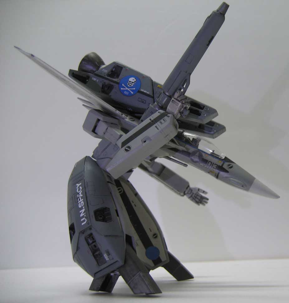
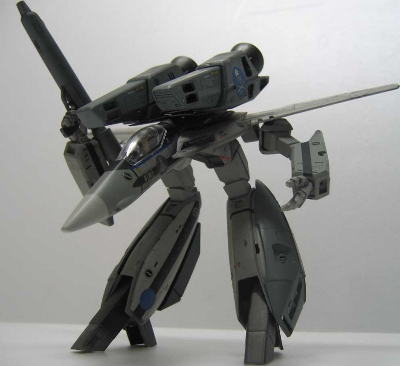
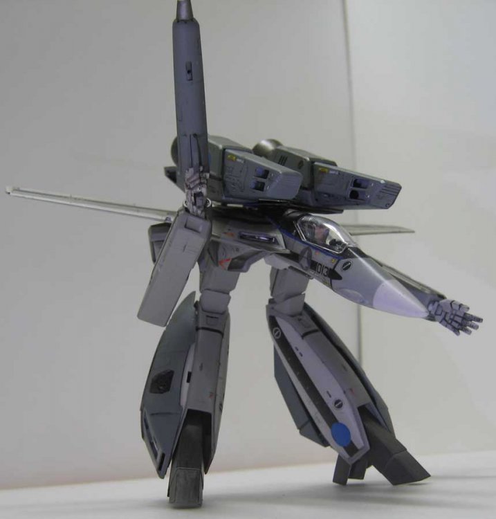
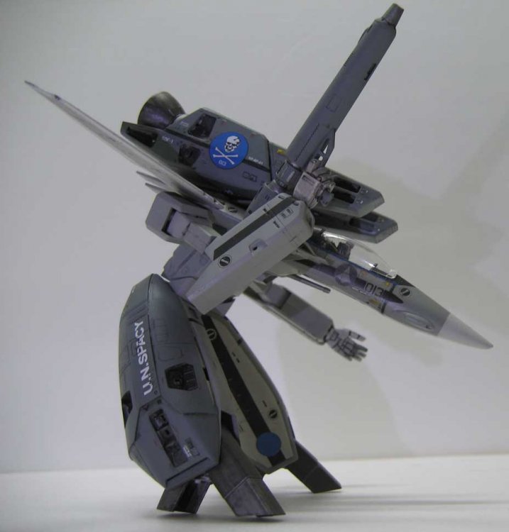
I don't do toys. Sorry if that sounds snooty, but building it is where all the joy is for me. Once I'm done I feel kind of sad in a way. It's like when your reading a great book and you can't wait to turn the page and find out what happens, but you also know that doing that puts you closer to the end of the book and you don't want it to end. ( Ahh the beautiful contradictions that make up life as a human being!) That being said, once it's done and on display, when I look at it, there is this feeling I get that can only come from the intimate Knowing that is gained from creating something with your own two hands, and your wits that has me swell with pride. I just don't think that could happen for me from spending $100+ on something and sticking it on a shelf. (not to knock any of you toy guys - to each his/her own, (singing) "It takes different strokes, it takes different strokes, it takes different strokes to move the world yes it does. It takes different storkes to move the wooooooorld" Edit --o.k. this is it so far-pretty much. Like I said, still some details left, and a few mistakes but all in all I like it and I'm pretty proud of it. (haven't done any model stuff in the last couple of months Too much life stuff getting in the way ) anywho, enjoy the pics. [attachmentid=38748] [attachmentid=38749] [attachmentid=38750] [attachmentid=38751]

-
Just posted my build-up Here
-
Oops double post.
-
Thanks. It's mostly done now just a few bits left.
-
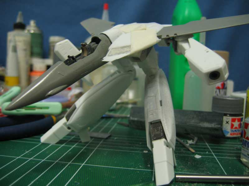
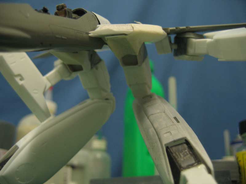
test fit [attachmentid=38740] [attachmentid=38741]


-
[attachmentid=38736] [attachmentid=38737] [attachmentid=38738] [attachmentid=38739]

-
6 this time [attachmentid=38730] [attachmentid=38731] [attachmentid=38732] [attachmentid=38734] [attachmentid=38735]


-
Next 5 [attachmentid=38725] [attachmentid=38726] [attachmentid=38727] [attachmentid=38728]


-
The next 5 [attachmentid=38720] [attachmentid=38721] [attachmentid=38722] [attachmentid=38723] [attachmentid=38724]


-
Pics [attachmentid=38714] [attachmentid=38715] [attachmentid=38716] [attachmentid=38717] [attachmentid=38718]


-
more again[attachmentid=38713] [attachmentid=38708] [attachmentid=38709] [attachmentid=38712] [attachmentid=38711] [attachmentid=38710]


-
[attachmentid=38707] [attachmentid=38706] [attachmentid=38705] [attachmentid=38703]More


-
Figures[attachmentid=38697][attachmentid=38698][attachmentid=38699][attachmentid=38700][attachmentid=38701]


-
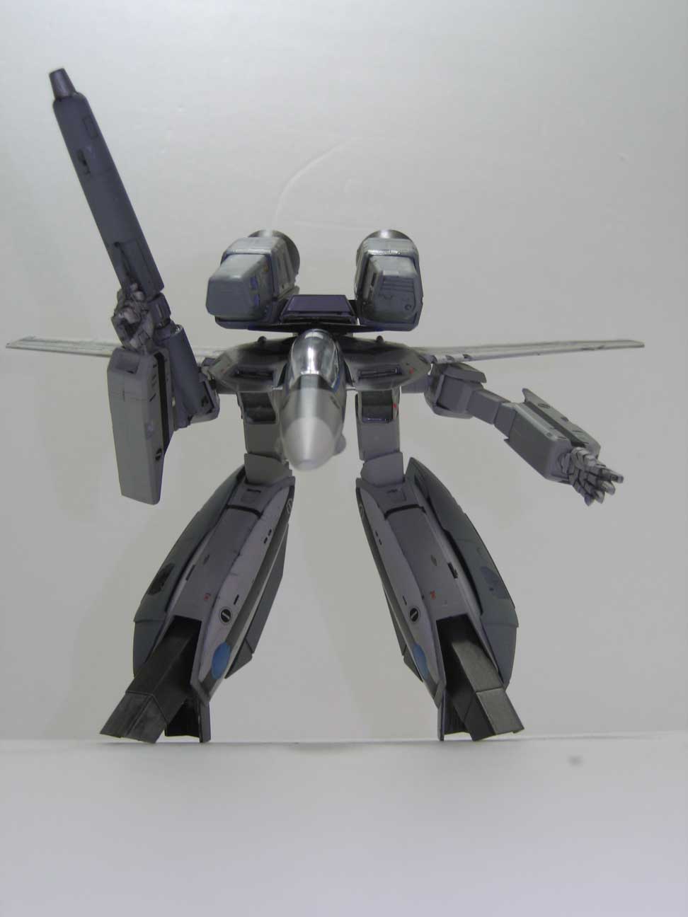
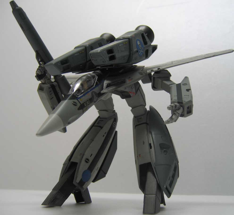
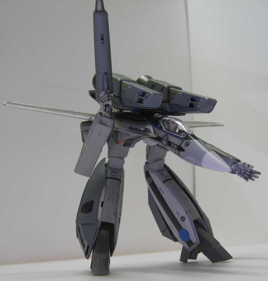
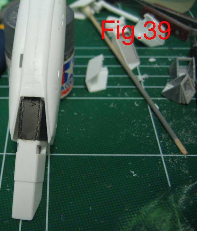
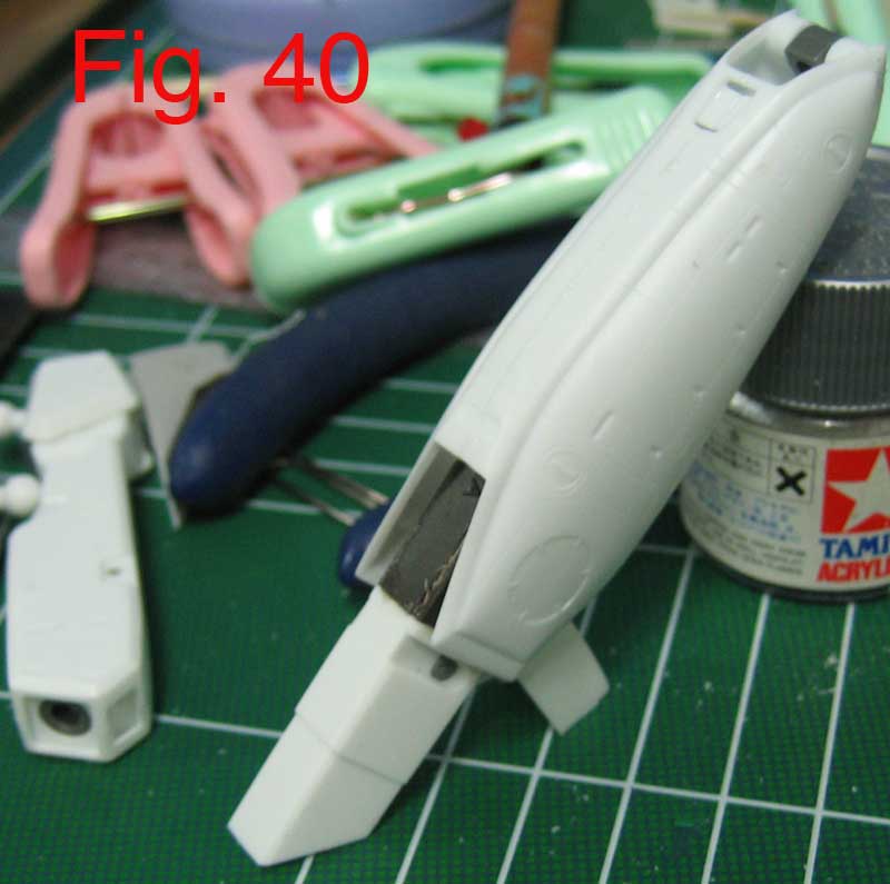
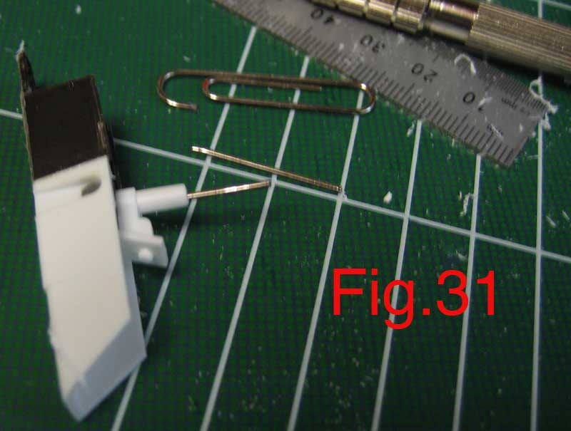
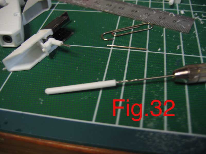
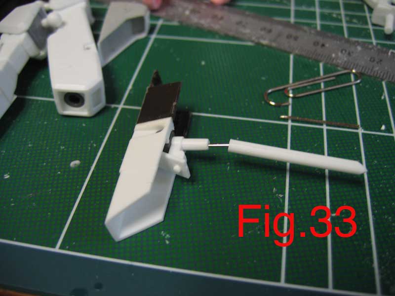
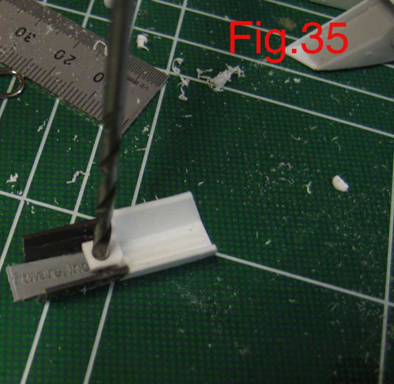
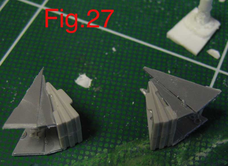
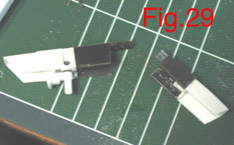
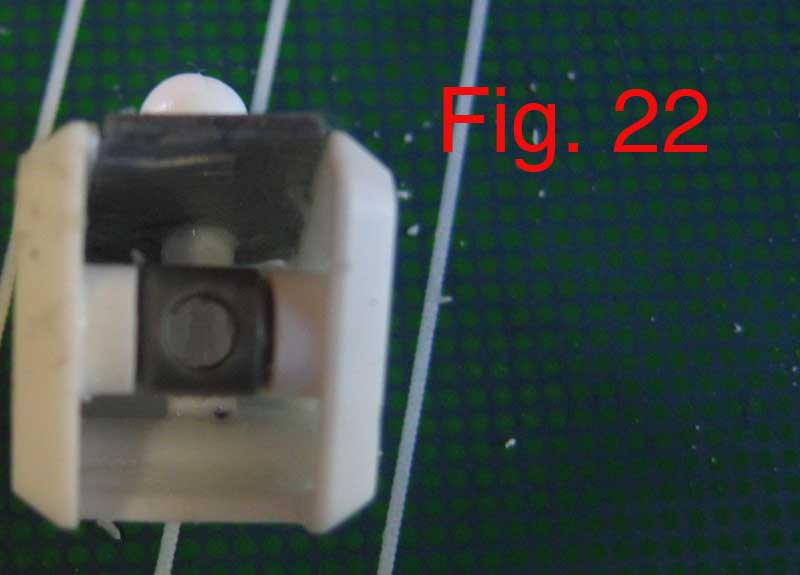
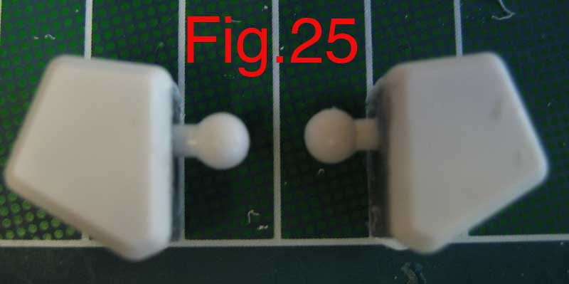
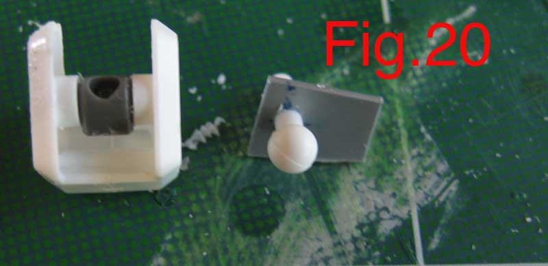
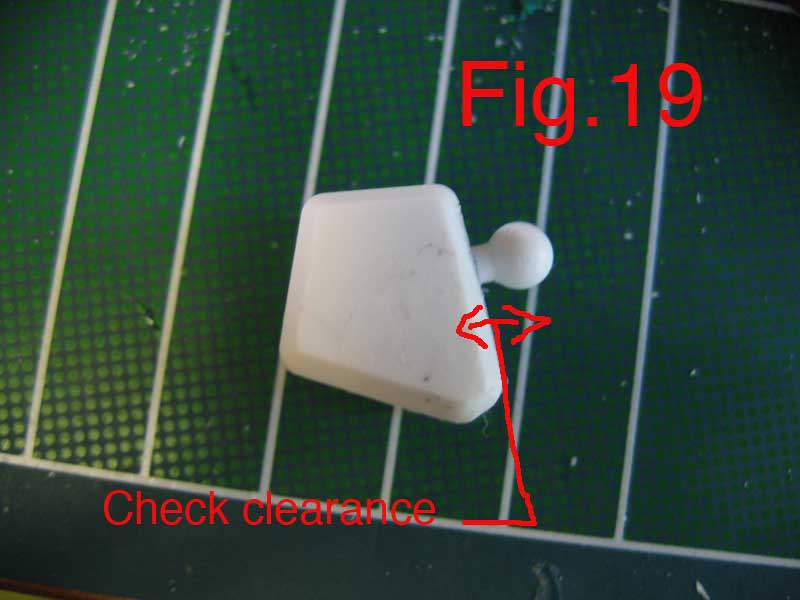
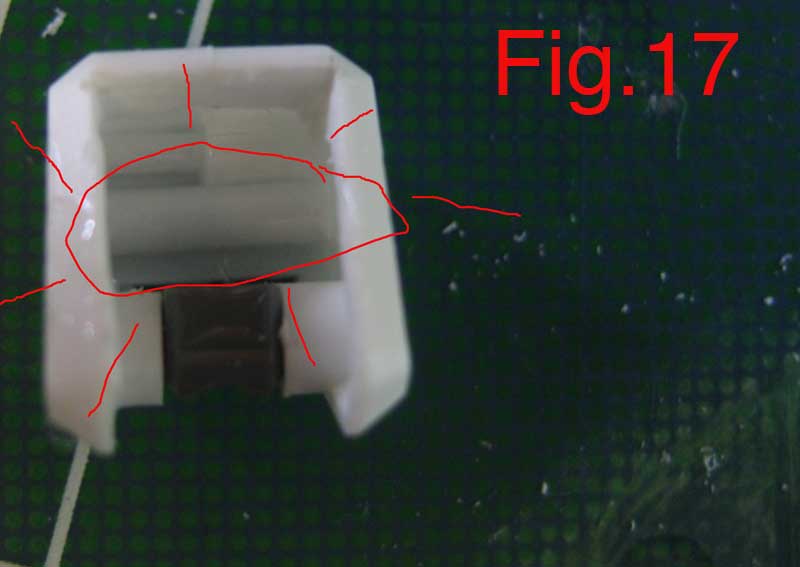
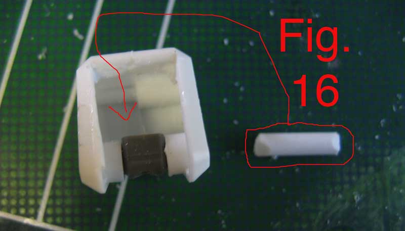
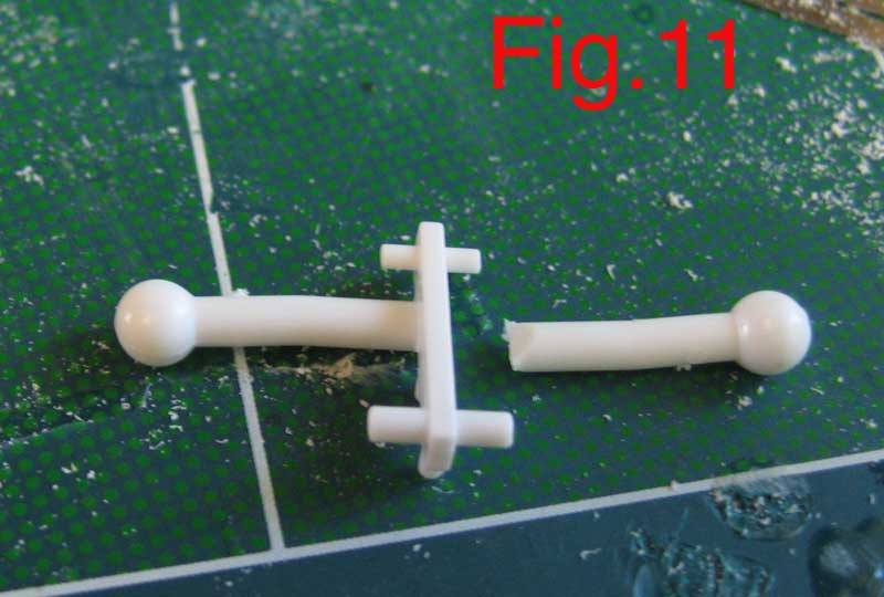
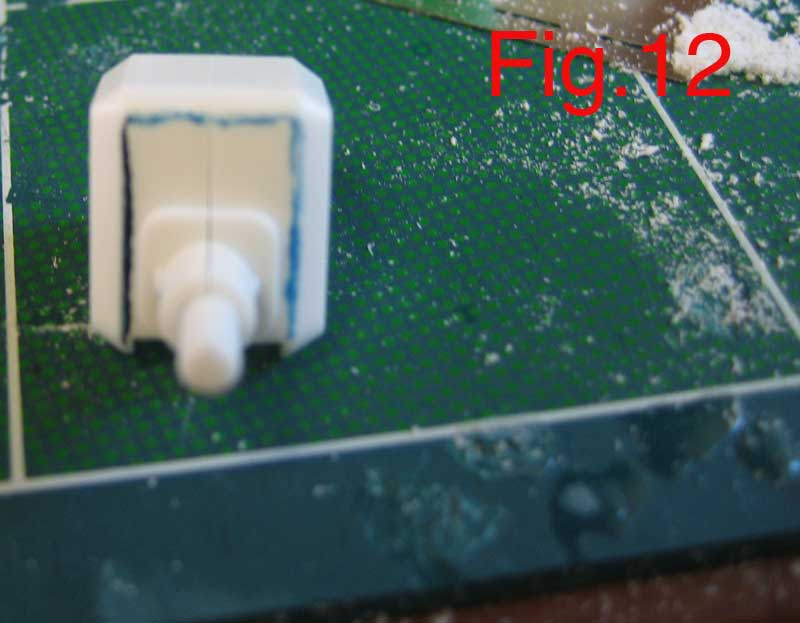
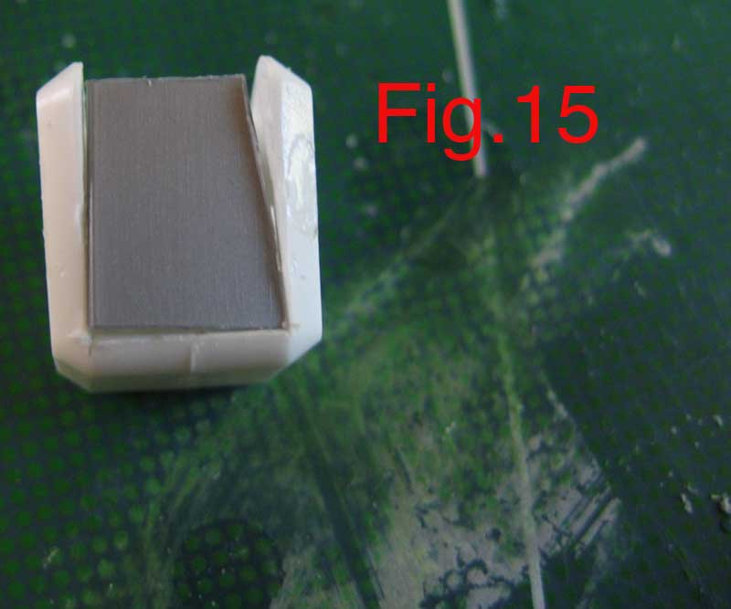
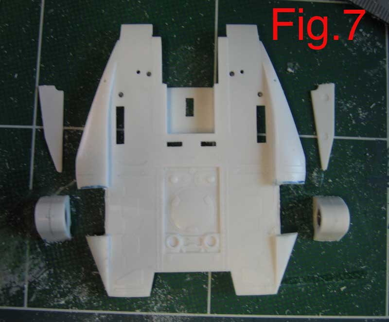
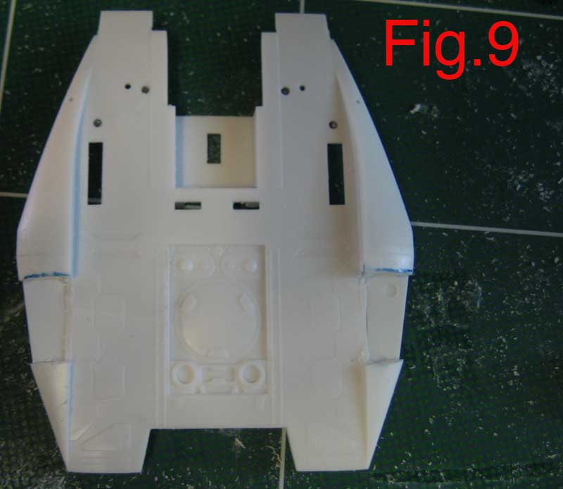
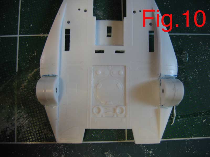
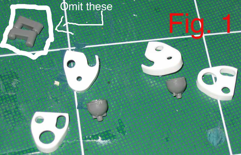
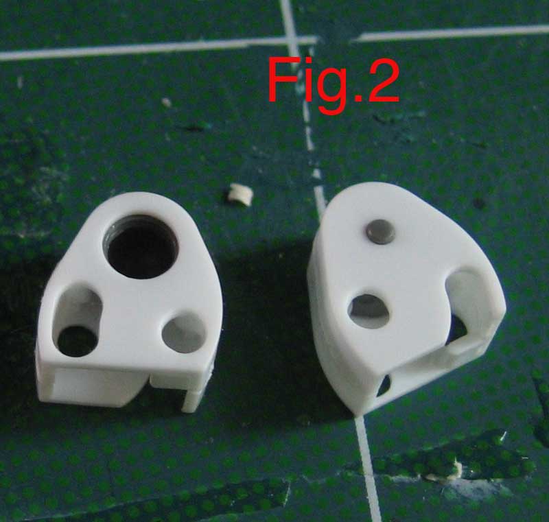
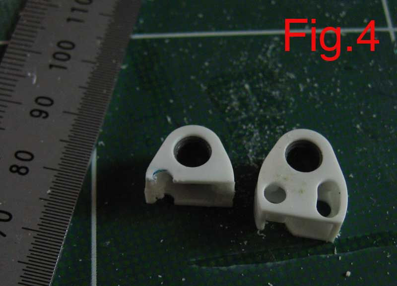
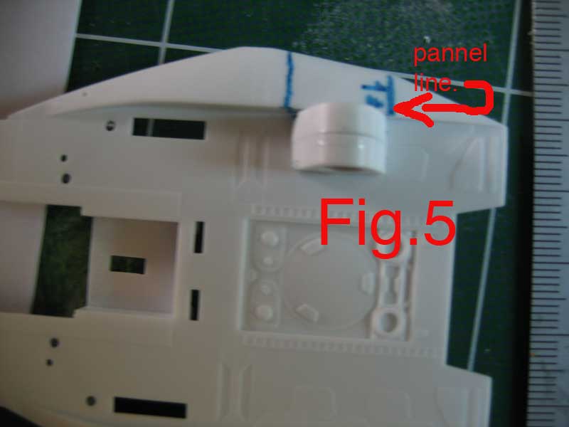
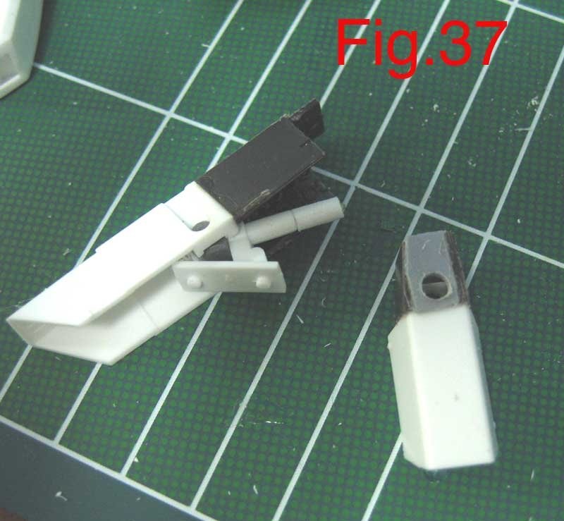
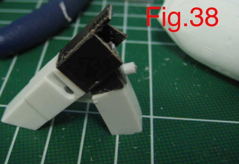
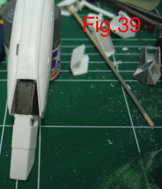
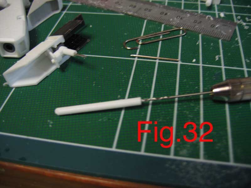
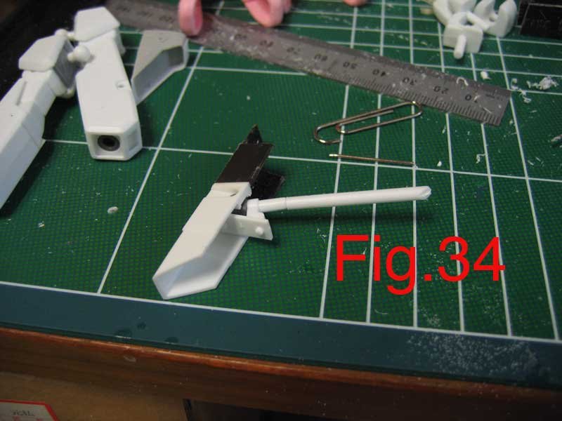
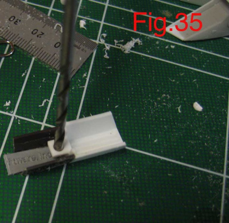
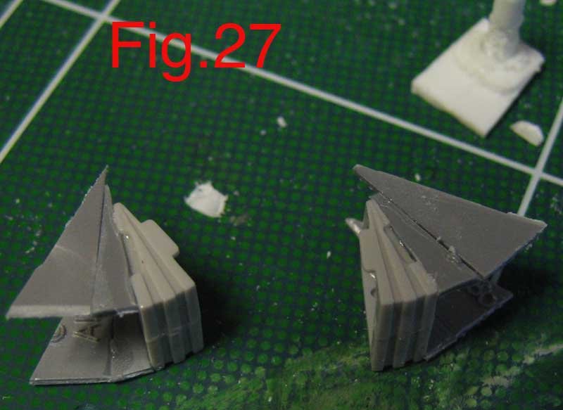
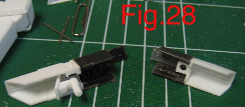
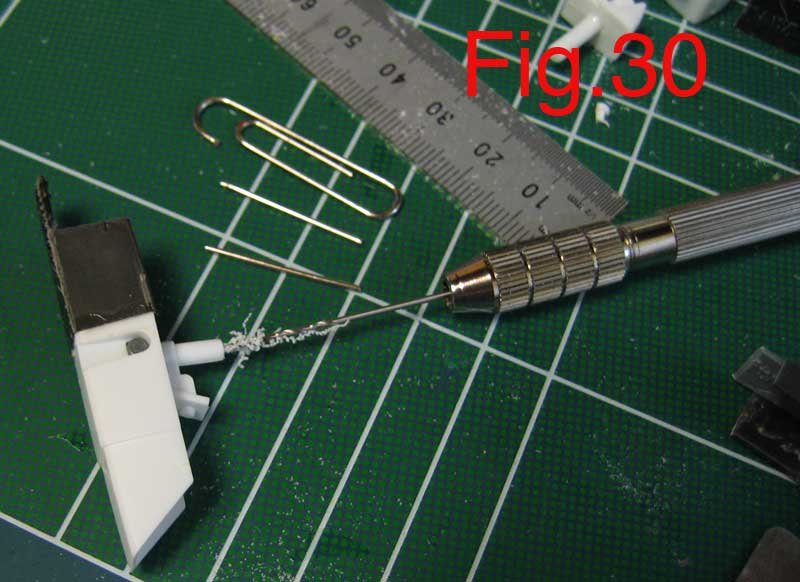
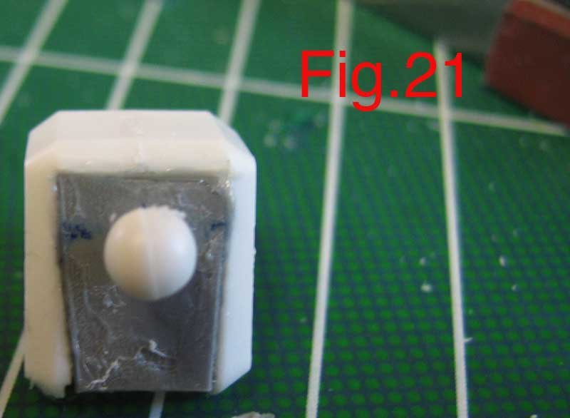
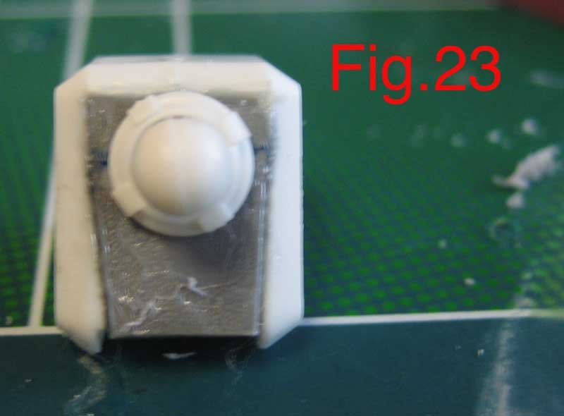
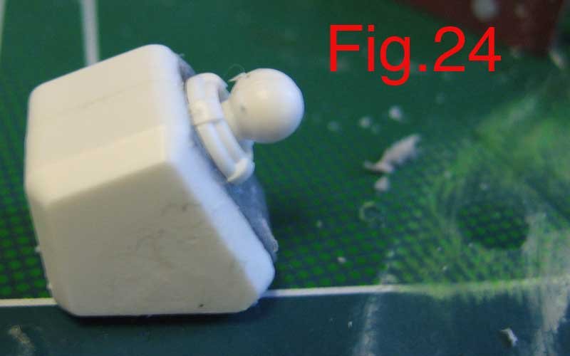
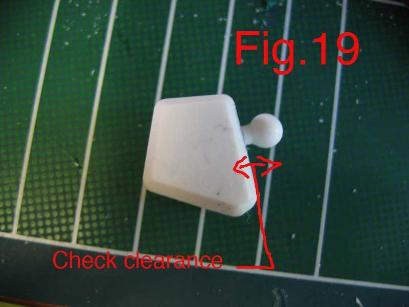
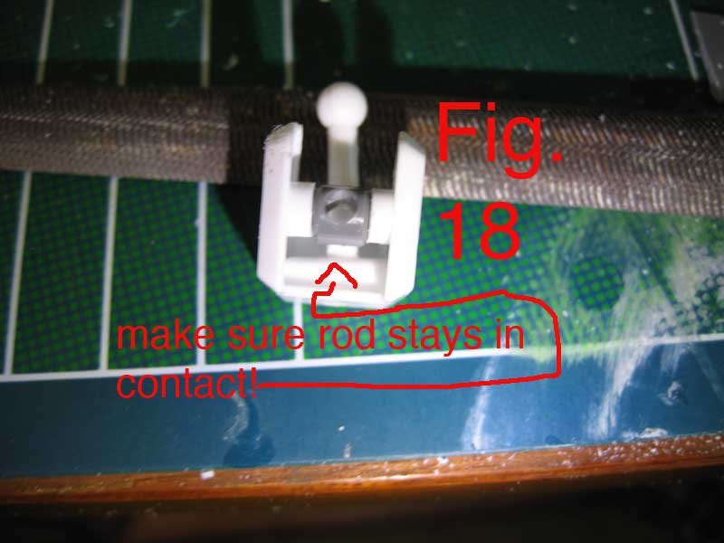
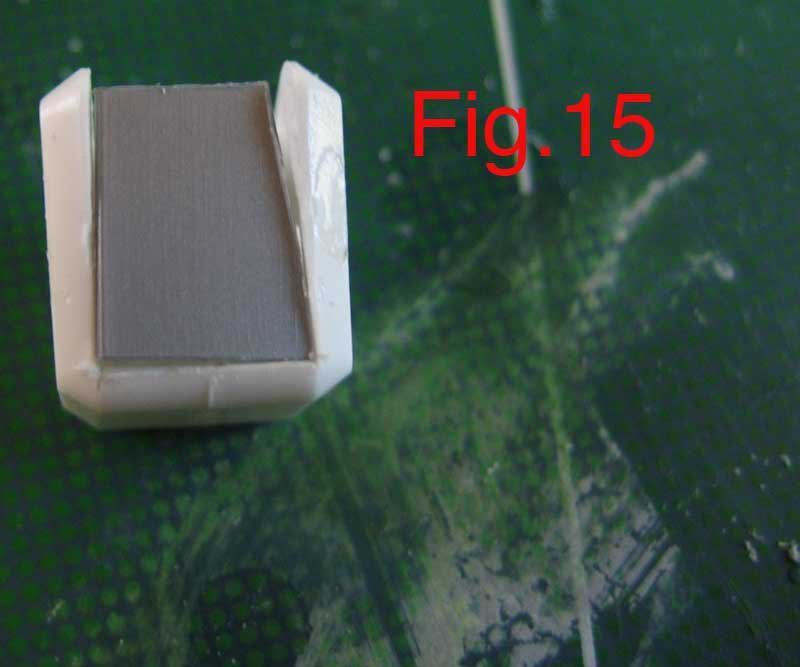
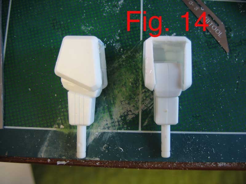
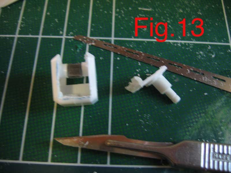
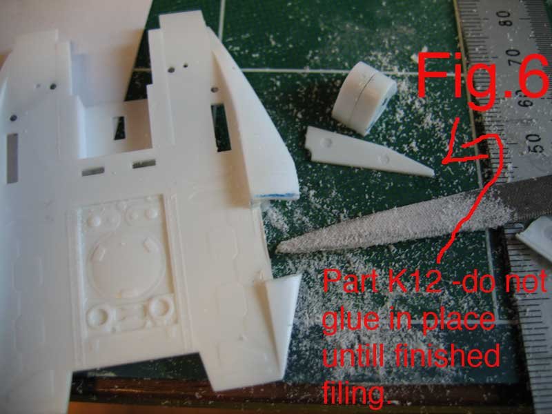
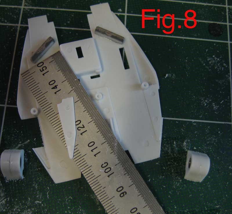
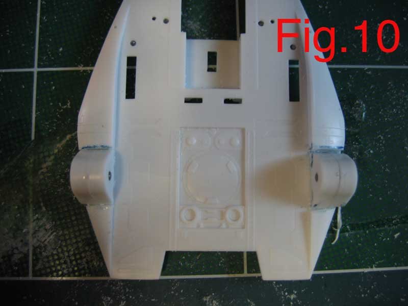
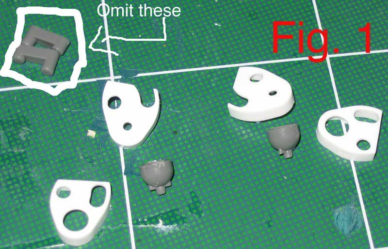
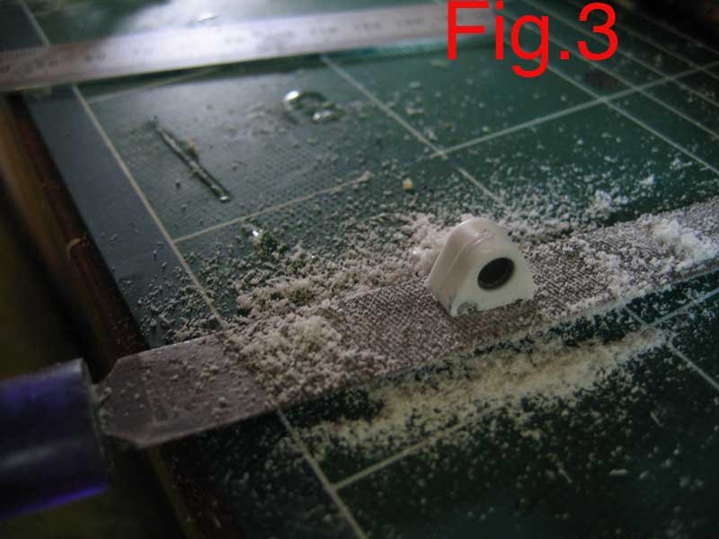
This is a semi-fixed-posed Gerwalk conversion for Hasegawa's Macross line of models. For this conversion I used a Hasegawa VF-1A fighter kit and a Vf-1A Super Battroid kit. I call this a semi-fixed-posed conversion because the 'hip' joint is fixed and immobile. The knee joint and thigh retain all of the mobility they were designed to have as do the shoulders and arms. As a starting point I began with the photo documentation of a similar project from the Oct 2002 issue of Hobby Japan (I say photo documentation because I do not read Japanese). I then went on to adjust this outline with some extra modifications of my own. SHOULDERS I will begin with the 'shoulder' modifications. For this we will use an altered version of the 'hip' socket from the battroid kit - Follow step #19 in the instructions that come with the kit leaving out part PC1 as it is unnecessary. Once assembled these pieces are filed down to roughly half their original height. See fig. 1-4. When this is done locate and remove part A5 from the fighter kit. Place the modified hip socket from the last step onto part A5 as shown in fig. 5 and mark it's position as shown. (note that the blue line on the right in the picture is on an existing panel line ( I suggest using this panel line as one of the end points of the modified hip socket.) Once the points have been marked the material between them needs to be removed, for this I use a file. (Note: do not attach piece K12 until after the filing is complete!) Once both sides of part A5 have been cleared of material glue in place, as per instructions, parts K12 and then securely glue the modified hip socket into the newly made slots. See fig. 5 - 10. Next we move on to the shoulder joint of the arm. For this we will start with part D1 from the battroid kit. Cut off the two ball and rod pieces at the mid point where they meet the perpendicular rectangle, (See fig.11). Next follow step #1 in the battroid assembly instructions and put the shoulders together. Once they have cured mark the rectangle that surrounds the rod assembly as in fig.12. (note this 'rectangle' is defined by the beveled edge of the shoulder on three sides.) once both shoulders have been marked proceed to cut this section out completely fig 13. For this I use a razor saw from Hasegawa's Tritool line. Remove both panels from the shoulder assemblies and put them aside, (you may use them later). Your shoulder should now look like fig.14. Next cut a piece of scrap styrene to fit in the hole you've just made. (I use the rectangular bits on the trees of the Hase kit that say which kit the tree belongs to, but any piece of scrap will do as long as it fits, and is a solid piece.) See fig.15 . Once these pieces have been fashioned put them aside in a safe spot. Next, cut a small section of leader from one of the trees this will be glued in place on the insde 'back' wall of the shoulder assembly to help anchor our new shoulder rod and ball section. I use a lot of glue here because I want it to become part of that wall, not just attached to it, (See fig. 16,17). Next place the rod and ball section you removed from part D1 into position, as in figs. 18&19 to check that there is enough clearance, but not too much space, between the flat inner-line of the shoulder and the ball-end of the rod. At the same time ensure that the flat end of the rod is making contact with the piece of leader that you glued inside the shoulder. Once you are satisfied with the clearance remove the rod and ball section and locate the piece of scrap styrene that you prepared earlier. While holding the piece of scrap beside the open hole where it will be placed, simply 'eyeball' how far down from the top the piece of leader that you glued in is and mark this location with a horizontal line on the piece of scrap styrene. After this is done find the middle of the scrap styrene (horizontally, not vertically) and then draw a line at this point from the top to the bottom. You have just located where you will drill the hole for the rod and ball section to go through. Be careful not to make the hole too big, if you do not have a bit that is the right size you can make the hole smaller and use a round file to increase it's diameter until it makes a snug fit for the rod (no jokes here please!) once this is done place the rod in the hole you've just made and glue everything securely in place. Do this for both shoulders (DUUUHHHH!)�- See figs. 20-25. LEGS Begin the legs by assembling parts U9+U11 and U12+U8 from the fighter kit. Set them aside to cure and while they are curing find some more scrap styrene and fashion some extensions for them, see figs.26&27 (note for the leg positioning I prefer for my gerwalk valks this section needs to be extended. You, however, may want to have a look at the position of the legs in the pics. at the end and decide for yourself if you want to extend this section and if so by how much you wish to extend it.) When these have been fabricated (if using) glue them in place as figs. 26&27. Proceed to complete leg assembly as per battroid kit instructions omitting all of steps 17 18 19 20 and 21, as the only parts you will be using from this section of the battroid leg assembly are parts C3, C2, C18, C19, and PC7(x2). Thus you will begin with step 22 in the battroid kit instrutions. FEET Note This modification is optional. I do not like the large gap that is left between the leg and the feet so I developed this to remedy that situation. Locate and remove from parts tree part numbers F28, and F18. Fabricate extensions for these from pieces of scrap styrene that are approximately 1.5cm in lenth and glue them inplace as per figs. 28 & 29. With this done locate a standard size paperclip and straighten as best as possible cut two pieces approximately 2cm in length and set aside. Locate a bit for your pin-vise that is the same diameter as your paperclip and drill a hole all the way through part F25 as shown in fig. 30 when this is done roll about half of one of the lengths of paperclip in some CA and insert it in the hole you have just drilled into part F25. See fig 31. Next take another length of leader from the parts tree and drill a corresponding hole of equal length in it, coat the remainder of the paperclip in CA and the tip of the leader with styrene cement and insert the remainder of the paperclip into the hole in the leader and push together firmly. See fig 32 Repeat this process for both feet. On part F18 you will note that the extensions you have added block in the hole provided for part F25 to pass through. To remedy this find a bit for your pin-vise that is the same diameter, or slightly smaller than that of the extension you just added to part F25 and drill a whole in the extension you've made to part F18 using the existing tab and hole as your guide. If needed use a round file to widen the diameter of the hole. Assemble feet and attach to legs. Note some trimming and other minor adjustment may be needed for a good fit. Complete the rest of the model as per instructions paint and detail to you liking and enjoy. I hope this tutorial proves helpful to those of you who choose to take on this project. Please note that some small adjustments to these instuctions may be needed for correct fit, but they are minor and depend greatly on the skill, experience and foresight of the modeler doing the building. If you have any difficulty or questions/problems feel free to ask, I'll do my best to help.
-
Why don't I just post it directly in this thread? Wel maybe that's not such a good idea as it has about 40 images plus the write-up. How about I start a new thread for it and you could then post a link to it in this thread?
-
Holly Crap! Is this thing that popular? The Cptain better watch out that his destroids don't get recasted before he's finished them
-
Wow! you want to mod a Hase. Valk. into that? I'm no expert on modding or scratch building (all I've done is a Hase. Gerwalk Mod) but it looks to me like that would require some major modifications. (Not something I would attempt for a first foray into modding kits -- difficult to the point of discouraging. Start off with something a little more straight forward so you have time to develop the skills and gain the experience need for such a major project. Small steps man Small steps! If you like I have a step by step of how I built my Gerwalk from a hase Battroid and fighter kit thay I could post.
-
I completely and wholehartedly agree with you. Recast all the out-of-production, event only, rare, never gonna see it again, stuff you want, BUT If it's a new creation still being produced then Hands-Off! That's why I posted on Neograde's site about it, 'cus this was their first (as far as I know) Macross kit and I want them to make more. HobbyFan 'aint never gonna produce anything new. That being said over on the SamuraiMonkey Forums Kylwell, HWR MKII, and myself have been talking abou this and . . . well it's easier to just post snippets of the conversation than to summarize it so: Kylwell: Last time I chatted with the owner of HF he was moving away from re-casting after a fashion but he admitted he doesn't check when someone approaches him with a subject.But in this case, I dunno. ME:Is that like -- it's to difficult to do the follow-up work and find out, or like the pawnbroker who doesn't ask questions when the same scruffy guy comes in every second week with ladies jewellery to pawn? What was your impression? Kylwell: Kinda. Some items he seemed to go out of his way to find the original scultor or manufacturer, some the master maker came to him with nothing more that a first pull, others may have just said it was thiers. To me there is a big gray area when it comes to re-casting, but this incident is definately more on the darker end of things. HWR MKII: HF is usually prety good at staying above board and honest on its recasts(as far as you can get recasting) They mainly stuck to OOP kits or WF only specials. This is a weird turn of events for them. Kylwell: Which is why I'm wondering if it was a third party who convinced him it was thiers. So it might not be anything more malicious than just not doing their homework. Who knows?
-
Well It has just been confirmed as a recast by the folks at Neograde as well. Link So I don't think HobbyFan will be able to continue offering it.
-
Well I just posted a message on the Neograde website about it so I'll know soon if it is a recast or an original.
-
1/55 Bandai "J" Head Laser Recast - Anyone Doing Plastic?
Chas replied to Skull-1's topic in The Workshop!
O.K. I'm a little unclear here What do you mean when you say "Plastic"? Recasts are usually made from Pollyurethane resin because it is widely available in the commercial marketplace. What other kind of "plastic" are you looking to get these things in? P.S. You could always buy some Styrene Rod and scratch build your own. -
Well its called a 'floor wax' but it is in fact a liquid acrylic clear coat. In my experience ( and I only use brushes-no air brush) it goes on easily and settles to a smooth even coat and it provides a terrific suface for the decals to adhere to. After I've applied the decals I use a little Microsol on them so they nestle into all the grooves and then another coat of future to seal. I've never had any silvering occur with the decals, well except for the first time - that time I applied too thin a coat of future - but since I learned that lesson no probs. I highly recommend the stuff. Plus one bottle will last for years! Best 7 bucks you'll spend.
-
Nice use of the tiny TB21 Did you have to vac-form your own canopies for the Club M kits? where did you get the vacu-form moulds? I'd love to get one of those 1/72 VF-4 kits. But alas, that is not to be (for the moment).